Download as PDF, PPTX

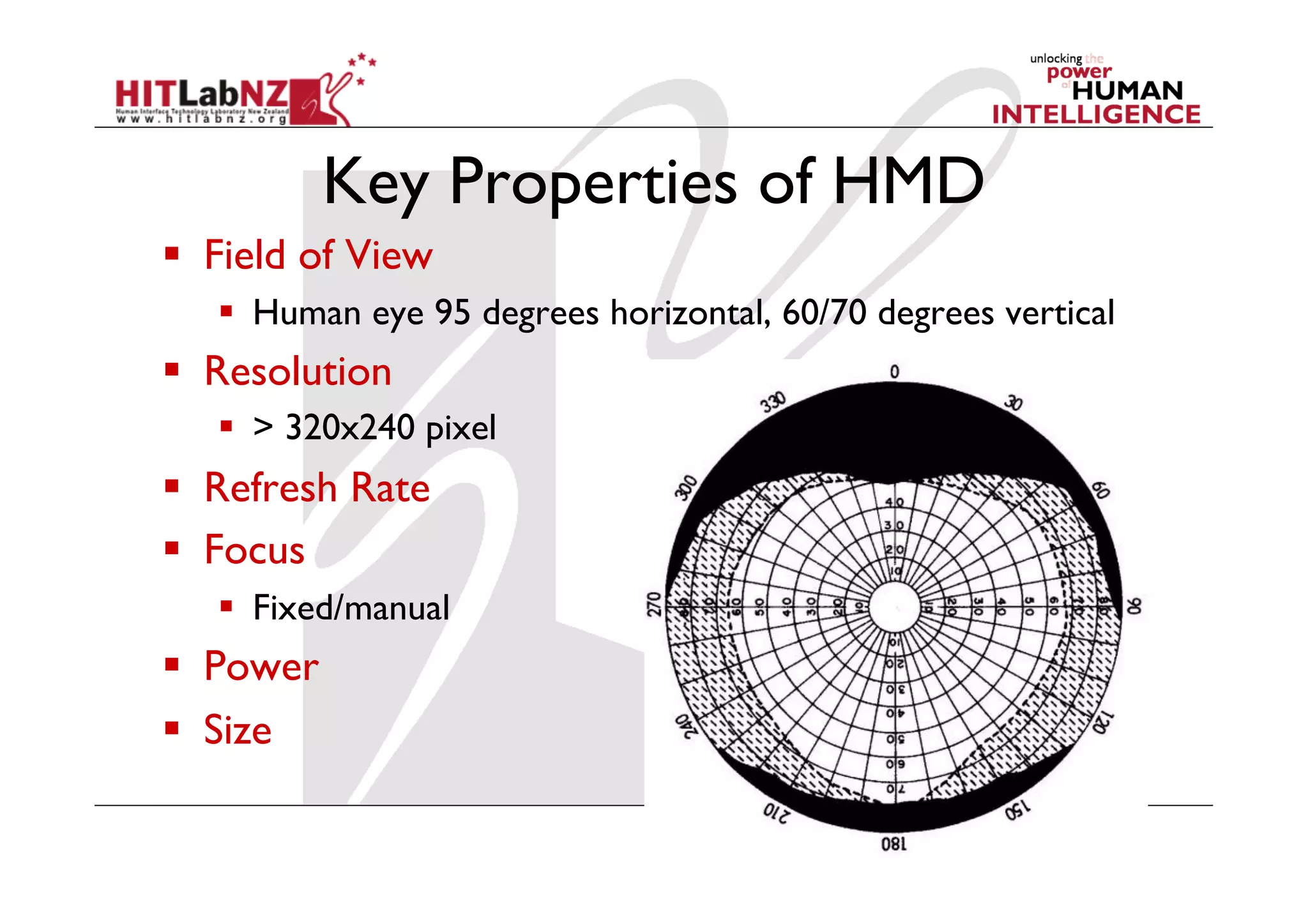
![Augmented Reality Definition
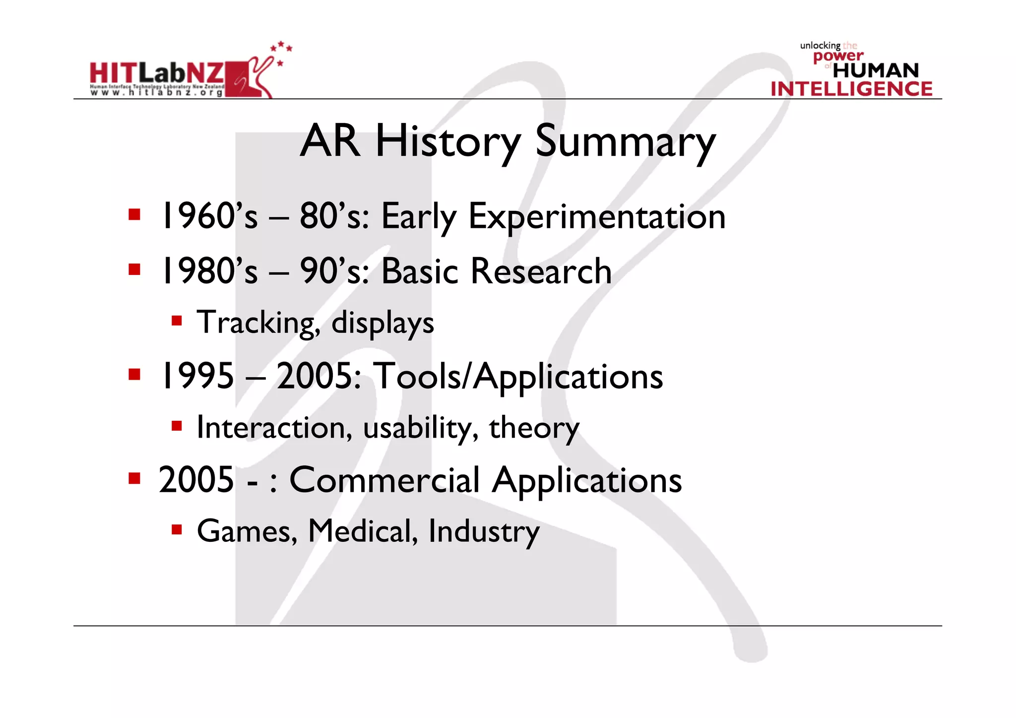
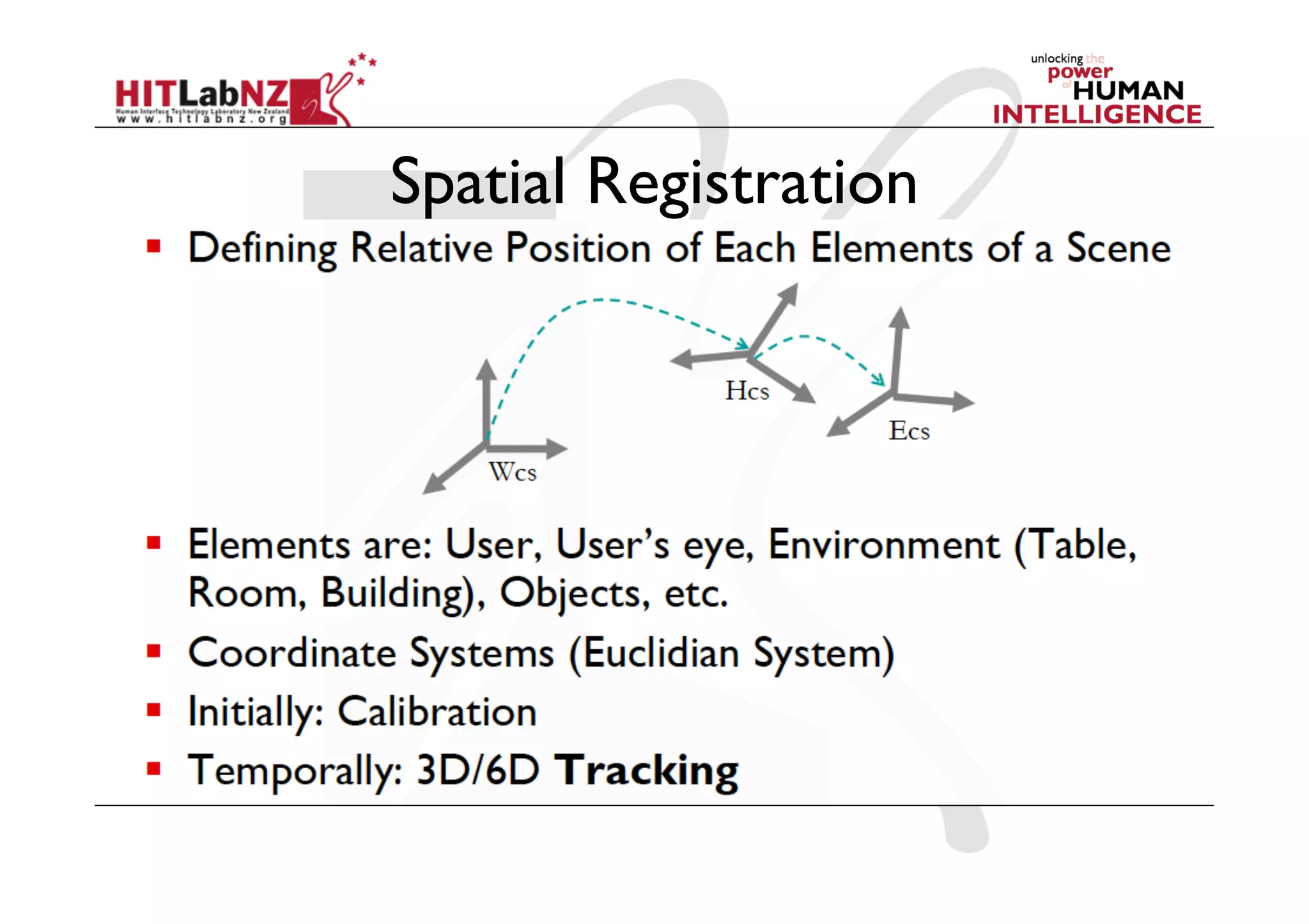
Defining Characteristics [Azuma 97]
Combines Real and Virtual Images
- Both can be seen at the same time
Interactive in real-time
- Virtual content can be interacted with
Registered in 3D
- Virtual objects appear fixed in space](https://image.slidesharecdn.com/2012-426lecture2-120719222849-phpapp01/75/426-lecture2-AR-Technology-3-2048.jpg)

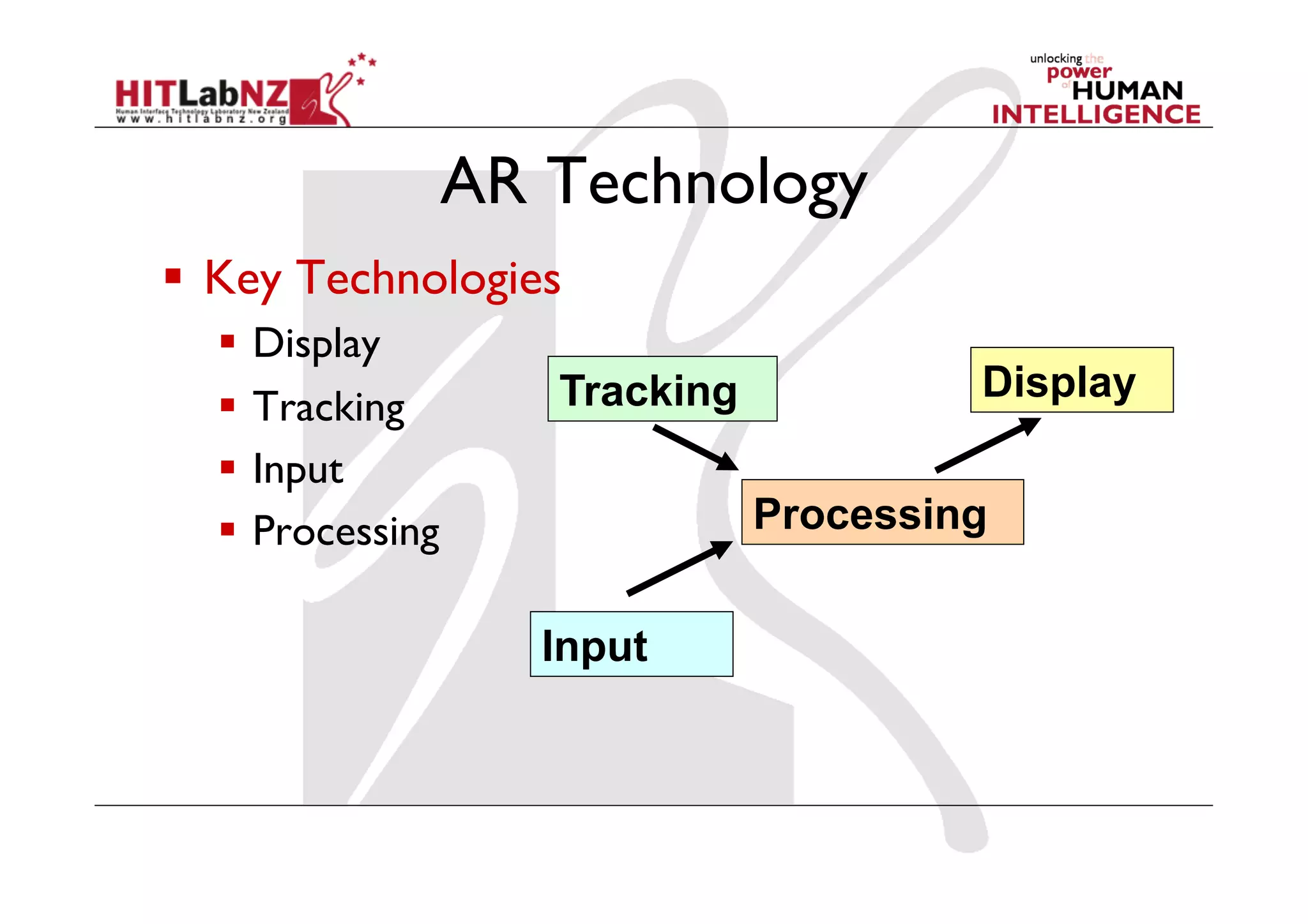
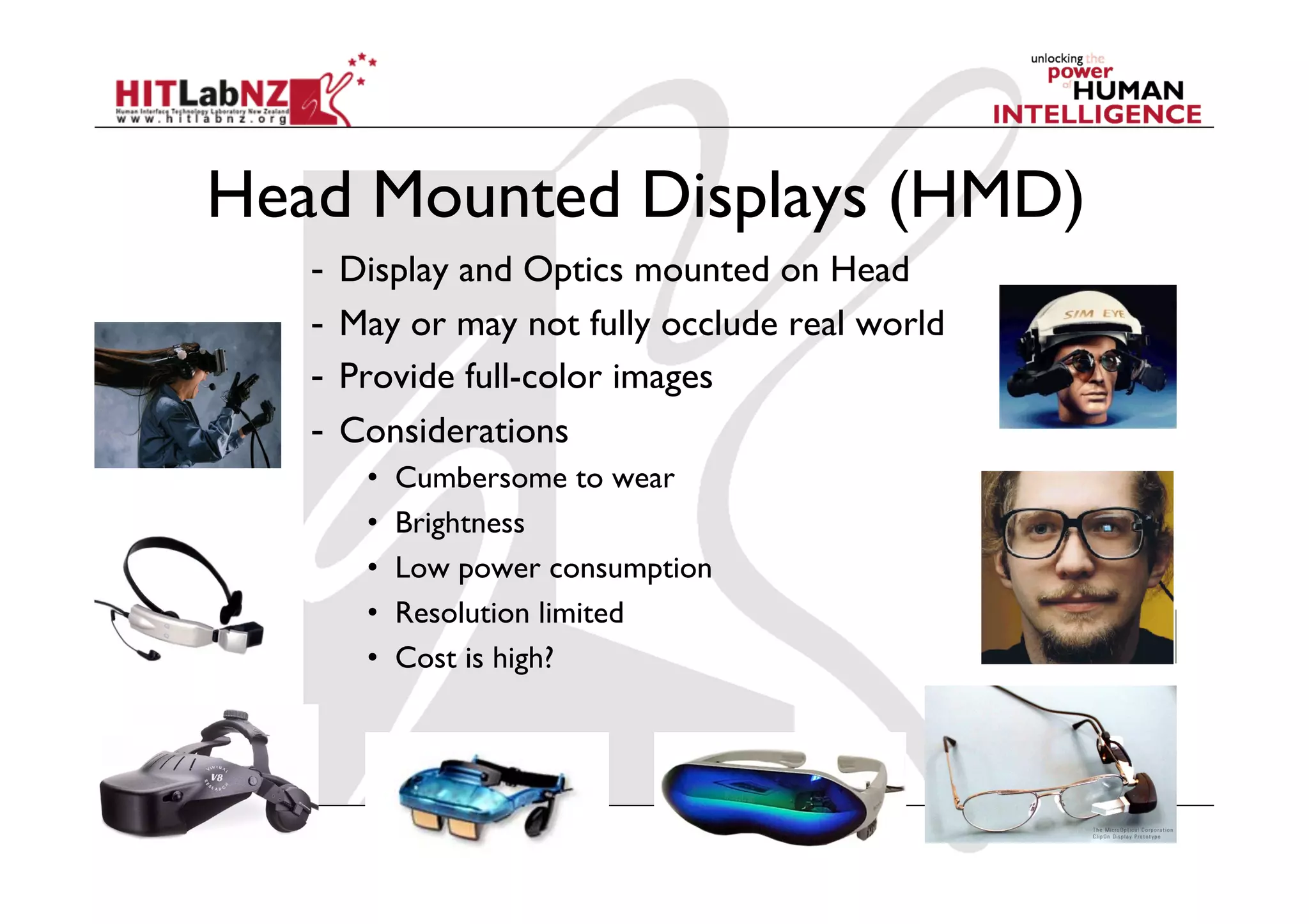
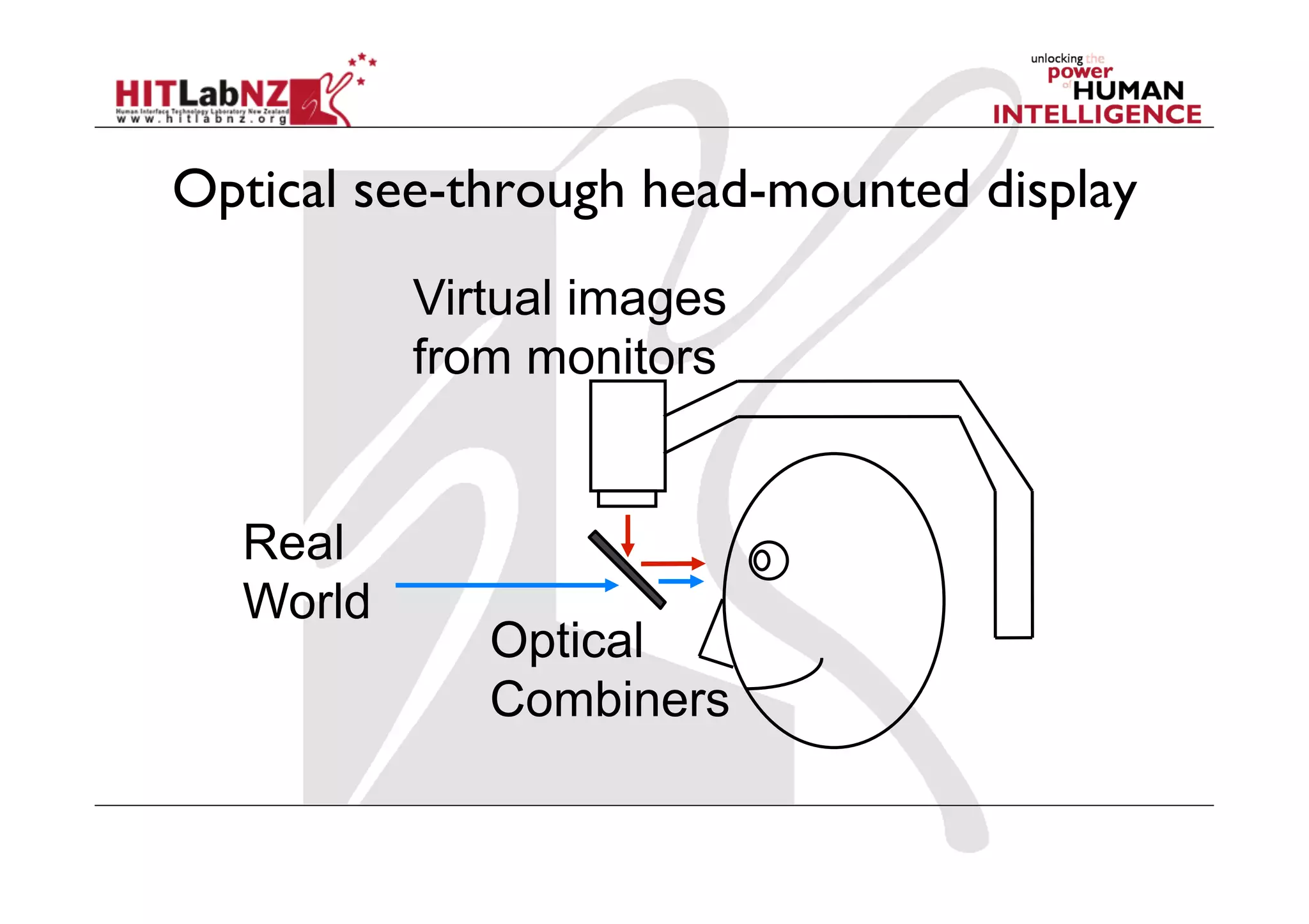
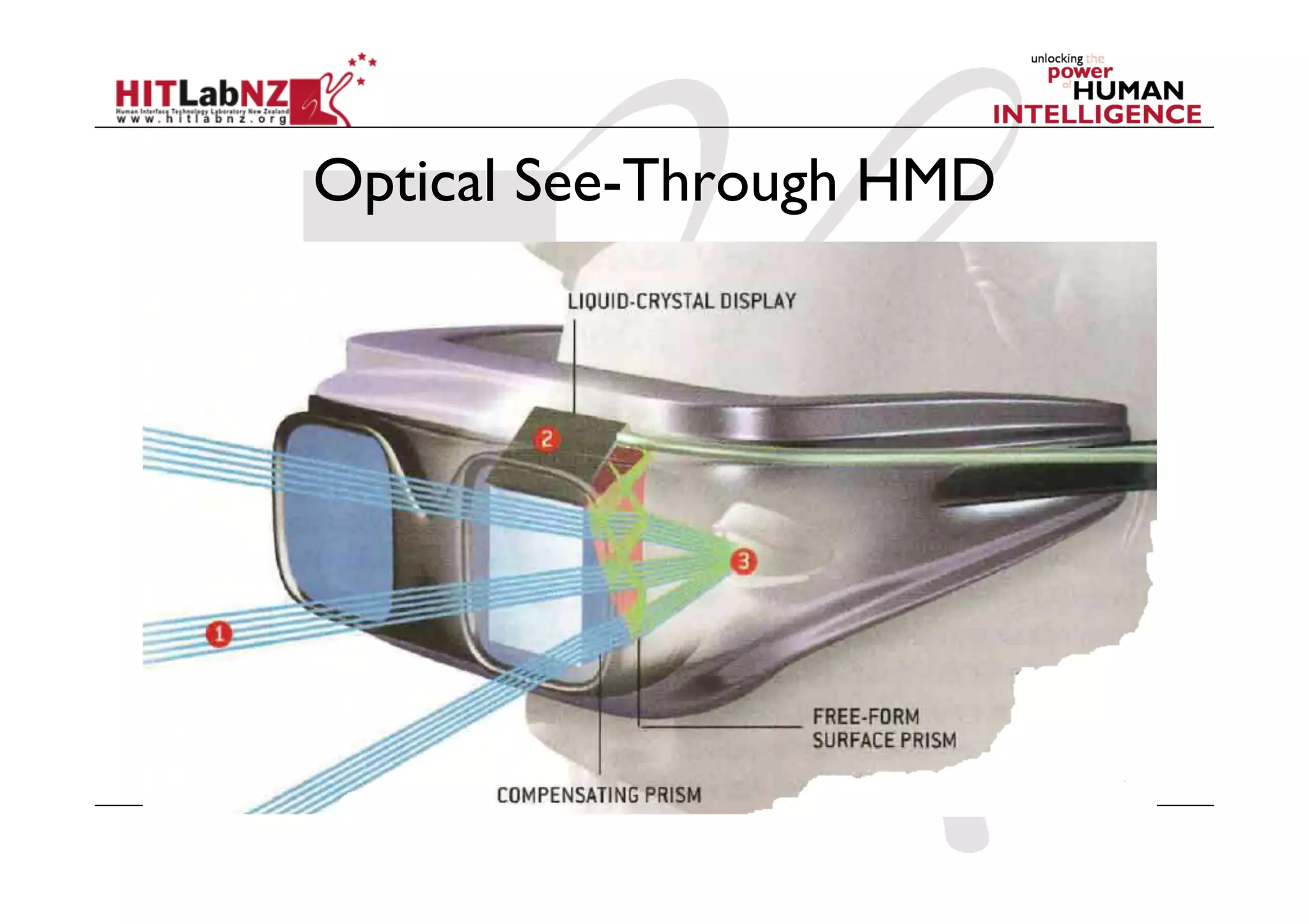
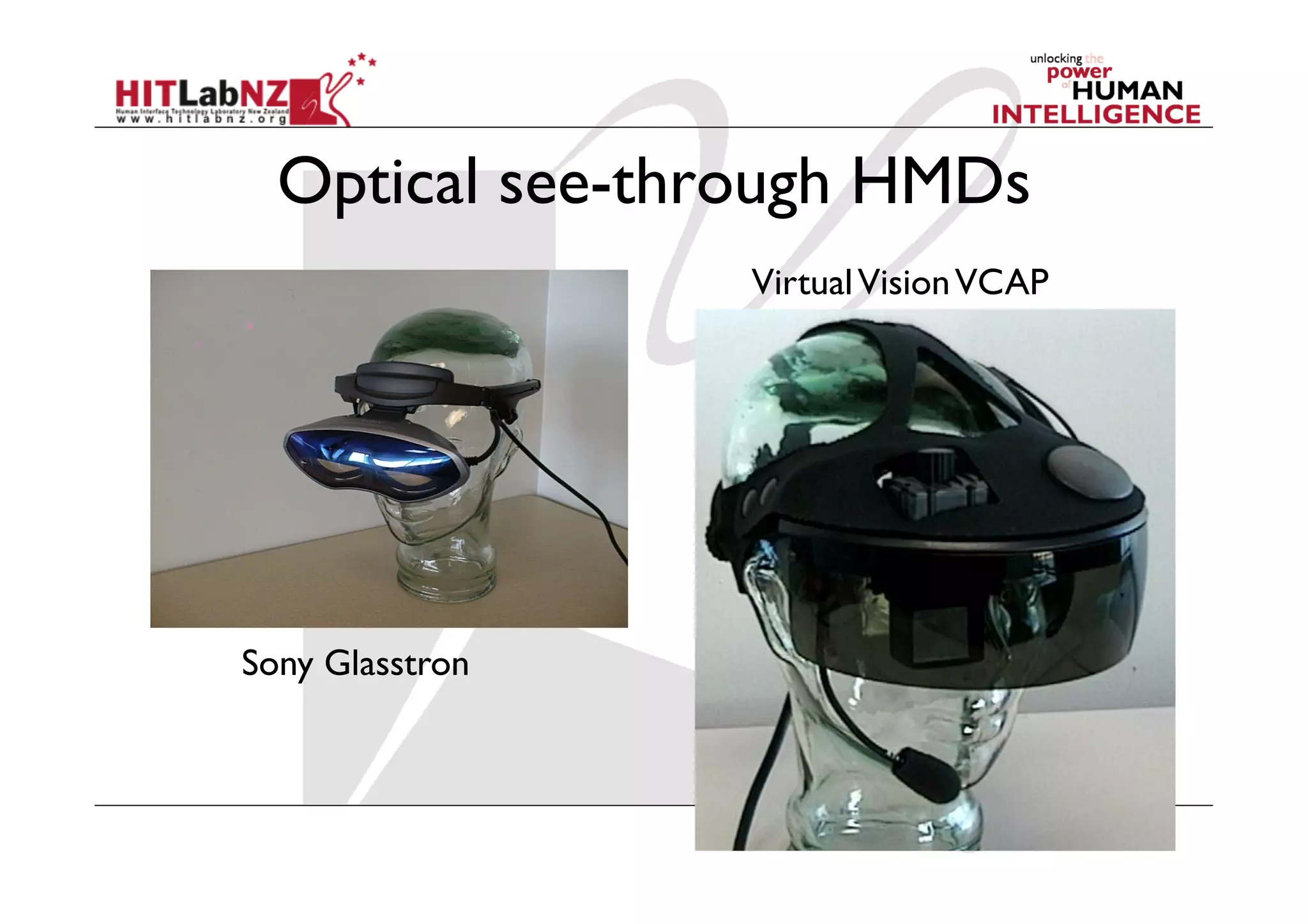
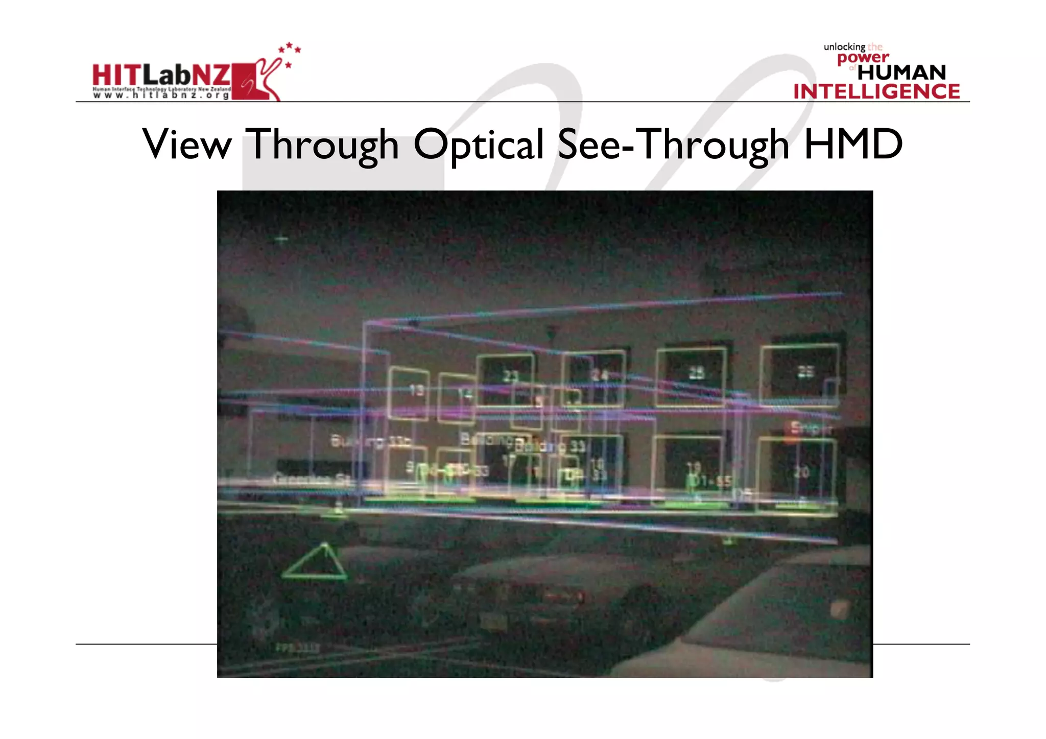

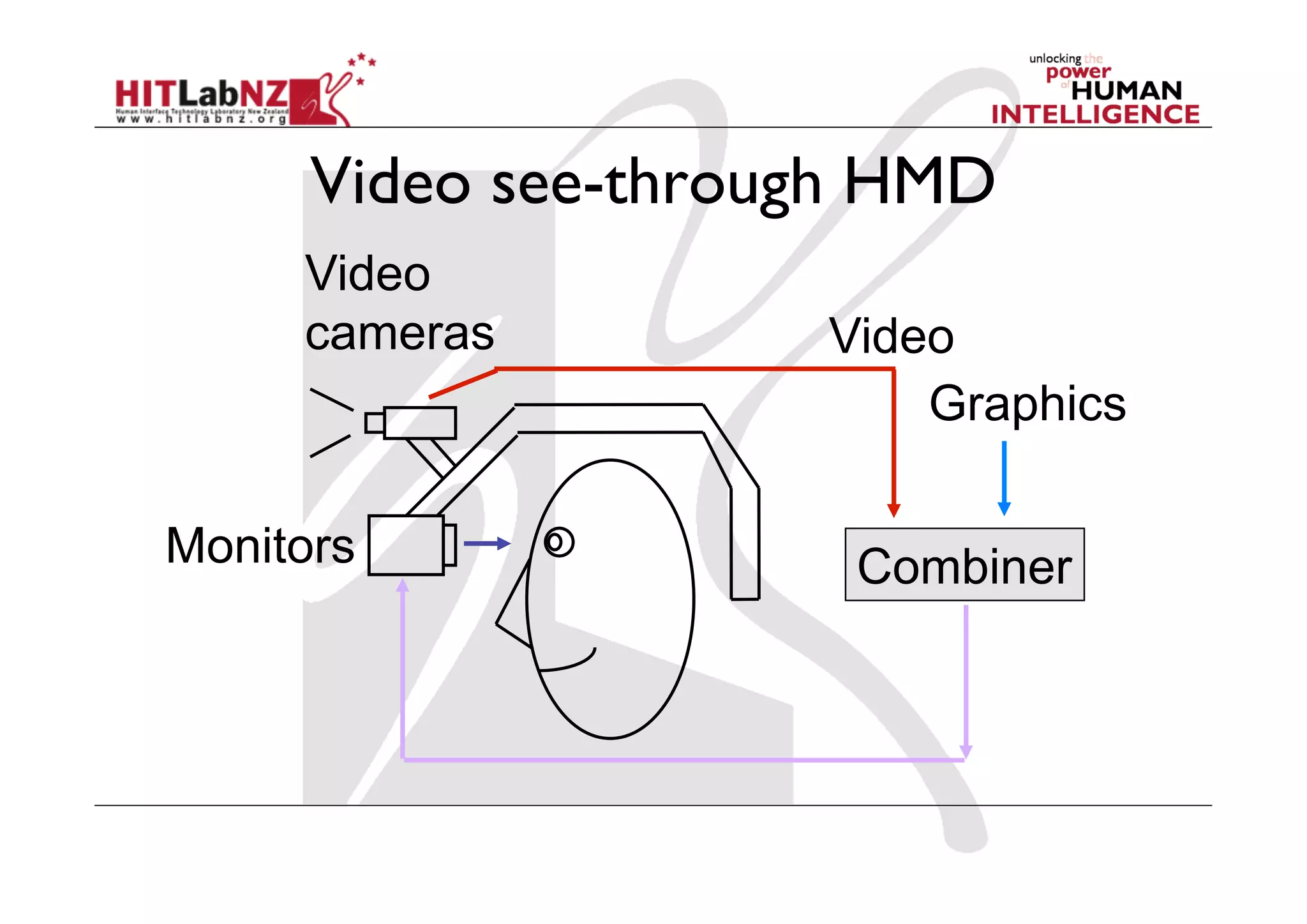
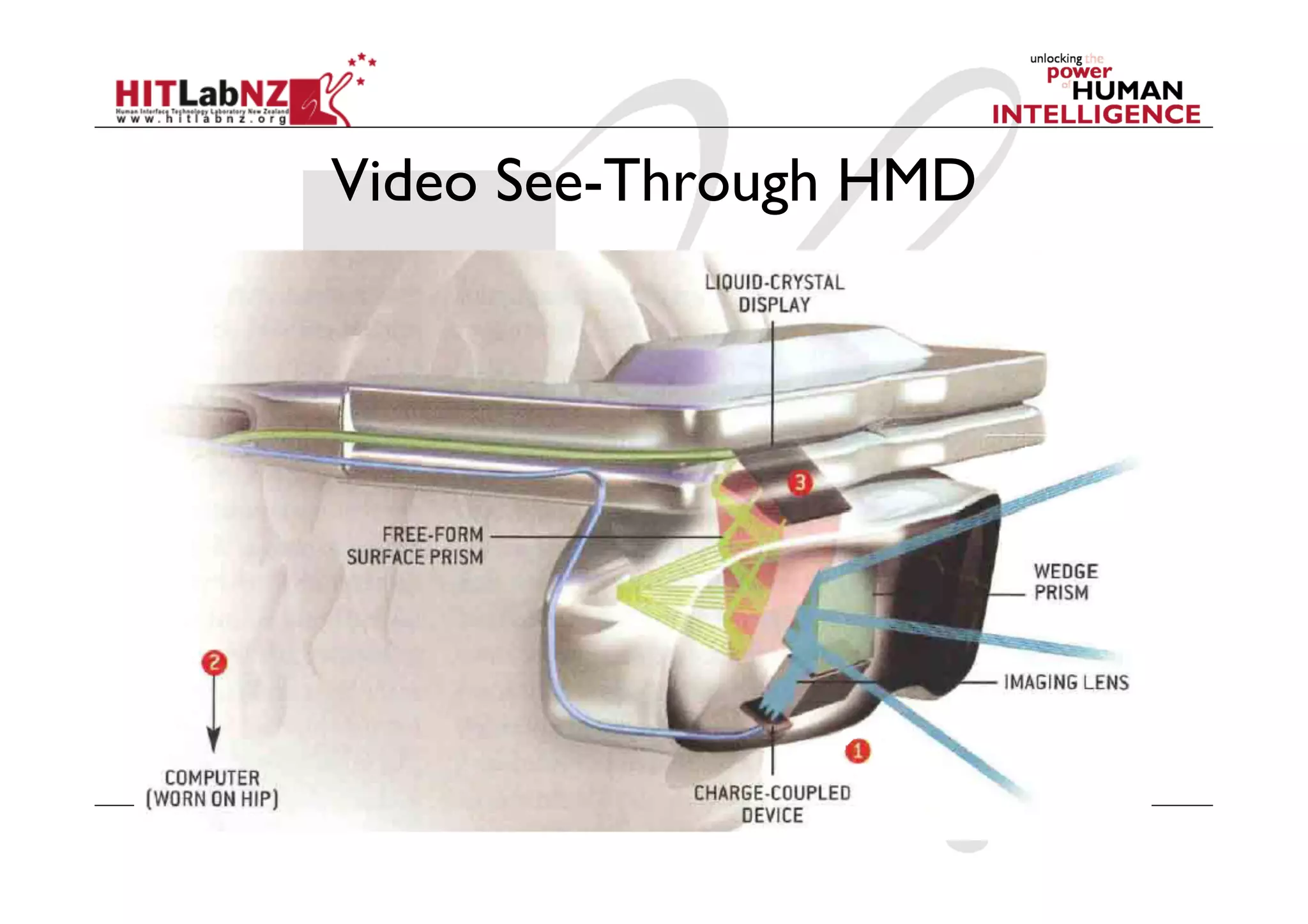
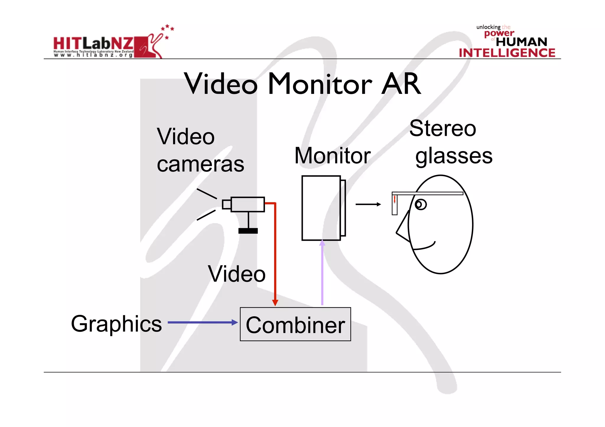
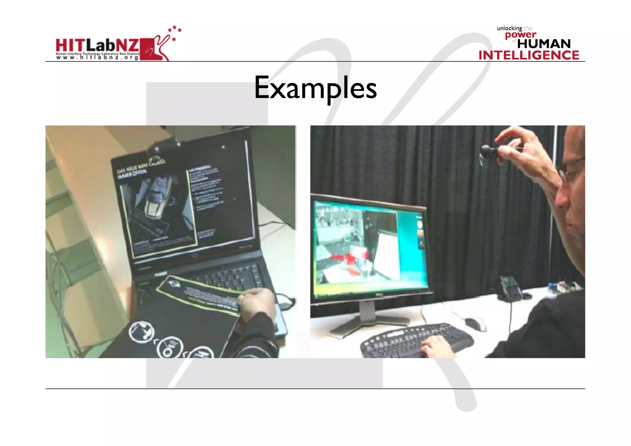


This document provides an overview of a lecture on augmented reality technology. It defines augmented reality and discusses its key characteristics. The lecture covers the history of AR, examples of applications, and the core technologies involved, including displays, tracking, and input methods. Head-mounted displays are discussed in depth as a primary display method for AR. Both optical and video-based see-through approaches for AR displays are presented.


![Coded Agents – with UiPath SDK + LangGraph [Virtual Hands-on Workshop]](https://cdn.slidesharecdn.com/ss_thumbnails/codedagentsdeck-251215155422-5497c599-thumbnail.jpg?width=640&height=640&fit=bounds)


