Downloaded 65 times


![Rate of change of centrifugal acceleration
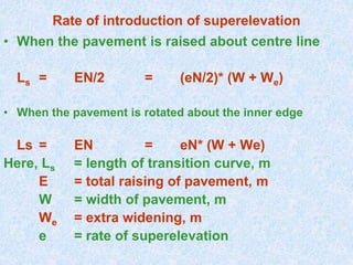
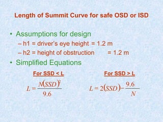
• Length of transition curve is calculated using
formula
Ls = v3/CR
here C = 80/(75 + V) m/sec3
[0.5< C < 0.8]
Here, Ls = length of transition curve, m
v = design speed in m/sec
V = design speed in Kmph
C = allowable rate of change of
centrifugal acc., m/sec3
R = radius of the circular curve
N = gradient](https://image.slidesharecdn.com/horizontalverticalhighwayalignment-200503033520/85/Geometric-Design-Horizontal-and-vertical-curves-40-320.jpg)
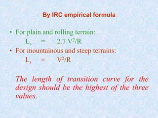
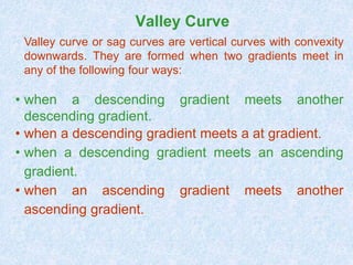
![Rate of change of Centrifugal Acceleration
or
Comfort Criteria
L = 2[Nv3/C]1/2
Where, L = total length of valley curve,
N = deviation angle
v = design speed, m/sec
C = is the allowable rate of change
of centrifugal acceleration
which may be taken as
0.6m/sec3.](https://image.slidesharecdn.com/horizontalverticalhighwayalignment-200503033520/85/Geometric-Design-Horizontal-and-vertical-curves-53-320.jpg)
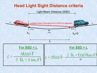
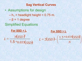

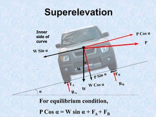
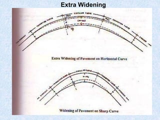
The document discusses key aspects of highway geometric design including horizontal and vertical alignment. It covers topics such as superelevation design, centrifugal force effects, transition curves, extra widening for curves, and vertical curve types. The key points are: - Superelevation is used to counteract centrifugal force when negotiating curves, and its design considers factors like design speed, radius of curve, and coefficient of friction. - Transition curves are used between tangents and circular curves to gradually change curvature and introduce superelevation for driver comfort. - Extra widening is required for curves to accommodate off-tracking of vehicles and driver tendencies, calculated based on number of lanes, wheel base, design


