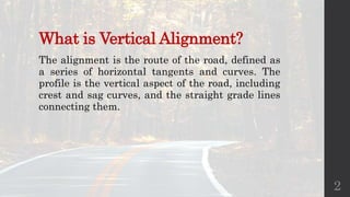
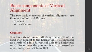
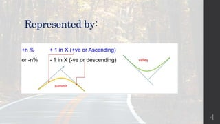
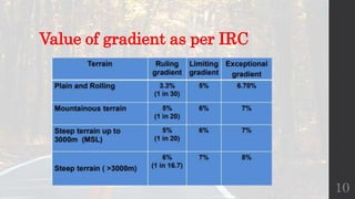
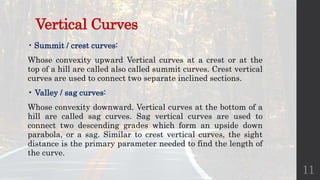
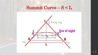
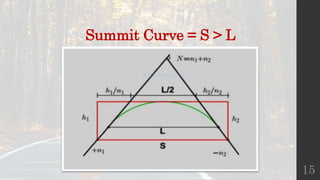
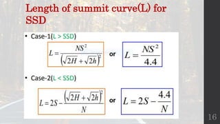
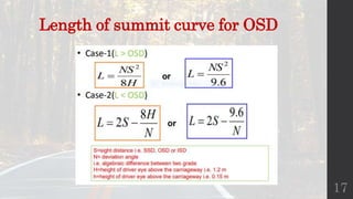
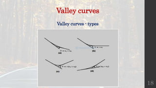
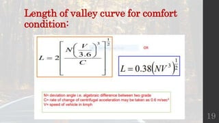
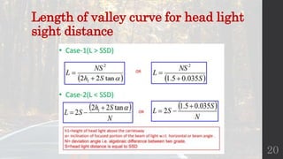
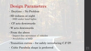
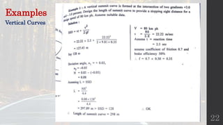
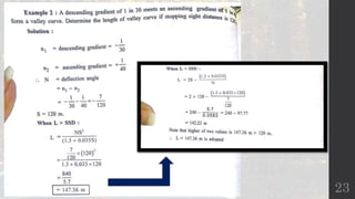
Design of
Vertical
Alignment
Komal Khetariya 181313140005
Dhavni Pandya 181313140006
Divy Patel 181313140007
Srishti Rana 181313140012
Wyman Chisanga 171310140065
1
What is Vertical Alignment?
The alignment is the route of the road, defined as
a series of horizontal tangents and curves. The
profile is the vertical aspect of the road, including
crest and sag curves, and the straight grade lines
connecting them.
2
Basic components of Vertical
Alignment
The two basic elements of vertical alignment are
Grades and Vertical Curves.
 Gradient
 Vertical Curves
Gradient:
It is the rate of rise or fall along the length of the
road with respect to the horizontal. It is expressed
as a ratio of 1 in x (1 vertical unit to x horizontal
unit). Some times the gradient is also expressed as
a percentage i.e. n% (n in 100) 3
Represented by:
4
Vertical Curves
Vertical Curves are the second of the two
important transition elements in geometric design
for highways, the first being Horizontal Curves. A
vertical curve provides a transition between two
sloped roadways, allowing a vehicle to negotiate
the elevation rate change at a gradual rate rather
than a sharp cut.
5
Mainly 2 components & Types
• Gradient (IRC)
 Ruling
 Exceptional
 Limiting
 Minimum
• Vertical Curves
 Summit Curves
 Valley Curves
6
Categories of Gradients:
1. Ruling or Design Gradient:
• Maximum gradient, within that the vertical profile is
designed
• Difficult to fix because depends on
– Type of terrain
– The length of the grade ( Change in speed affected by the length)
– The design speed (classification of roads)
– Pulling power of the Vehicles
– Presence of horizontal curve ( provide flatter gradient)
3% for plain, 5% for Rolling, 7 % for Hilly
7
2. Limiting Gradient:
• Steeper than the ruling gradient
• Provide due to topographic constraints
• Extra care required
– Place a level stretch or easier grade between longer limiting grades
– 5% for Plain and Rolling, 7 % for Hilly,
3. Exceptional Gradient:
• Provided in extreme difficult situations
• Steeper than the limiting
• For only shorter stretches ( not > 60 m in one Km)
• 7% for Plain and Rolling, 8% for hilly
8
4. Minimum Gradient
• Provided to drain out the water along the side drains and
depends
– Surface of the drains ( earthen, R.C.C ….)
– Rainfall Run-off
– Type of soil
– Topography and site condition
• 0.2% for used generally
• 1% for earthen or open drains
9
Value of gradient as per IRC
10
Vertical Curves
• Summit / crest curves:
Whose convexity upward Vertical curves at a crest or at the
top of a hill are called also called summit curves. Crest vertical
curves are used to connect two separate inclined sections.
• Valley / sag curves:
Whose convexity downward. Vertical curves at the bottom of a
hill are called sag curves. Sag vertical curves are used to
connect two descending grades which form an upside down
parabola, or a sag. Similar to crest vertical curves, the sight
distance is the primary parameter needed to find the length of
the curve.
11
Shape of Summit Curve
1. Circular
 Equal Sight distance at all points
 Most Ideal
2. Parabola
 Good riding comfort
 Calculation of ordinates
 Laying out on ground
 Most preferred
For small deviation angles above shapes doesn’t
make substantial difference
12
Design Parameters for Length
• Sight Distance
 Stopping Sight Distance
 Overtaking Sight Distance
• Centrifugal Force
 Acts Upwards
 Counteracted by weight of vehicle
13
Summit Curve – S < L
14
Summit Curve = S > L
15
16
Length of summit curve(L) for
SSD
Length of summit curve for OSD
17
Valley curves
18
Valley curves - types
Length of valley curve for comfort
condition:
19
Length of valley curve for head light
sight distance
20
Design Parameters
• Daytime – No Problem
• SD reduces at night
 SSD under head lights
• CF acts downwards
• W acts downwards
• From the above
 Impact free movement of vehicles
 Availability of SSD
• Transition curves – for safely introducing C.F (P)
• Cubic Parabola shape is preferred 21
Examples
Vertical Curves
22
23
References
• https://www.slideshare.net/LATIFHYDERWadho/vertical-alignment-
61082876?qid=21121f13-e8cd-41cb-80b1-
470bde303d96&v=&b=&from_search=2
• https://www.slideshare.net/srinivas2036/vertical-alignment-45013098
24
End
Questions?
25

Design of vertical alignment

  • 1.
    Design of Vertical Alignment Komal Khetariya181313140005 Dhavni Pandya 181313140006 Divy Patel 181313140007 Srishti Rana 181313140012 Wyman Chisanga 171310140065 1
  • 2.
    What is VerticalAlignment? The alignment is the route of the road, defined as a series of horizontal tangents and curves. The profile is the vertical aspect of the road, including crest and sag curves, and the straight grade lines connecting them. 2
  • 3.
    Basic components ofVertical Alignment The two basic elements of vertical alignment are Grades and Vertical Curves.  Gradient  Vertical Curves Gradient: It is the rate of rise or fall along the length of the road with respect to the horizontal. It is expressed as a ratio of 1 in x (1 vertical unit to x horizontal unit). Some times the gradient is also expressed as a percentage i.e. n% (n in 100) 3
  • 4.
  • 5.
    Vertical Curves Vertical Curvesare the second of the two important transition elements in geometric design for highways, the first being Horizontal Curves. A vertical curve provides a transition between two sloped roadways, allowing a vehicle to negotiate the elevation rate change at a gradual rate rather than a sharp cut. 5
  • 6.
    Mainly 2 components& Types • Gradient (IRC)  Ruling  Exceptional  Limiting  Minimum • Vertical Curves  Summit Curves  Valley Curves 6
  • 7.
    Categories of Gradients: 1.Ruling or Design Gradient: • Maximum gradient, within that the vertical profile is designed • Difficult to fix because depends on – Type of terrain – The length of the grade ( Change in speed affected by the length) – The design speed (classification of roads) – Pulling power of the Vehicles – Presence of horizontal curve ( provide flatter gradient) 3% for plain, 5% for Rolling, 7 % for Hilly 7
  • 8.
    2. Limiting Gradient: •Steeper than the ruling gradient • Provide due to topographic constraints • Extra care required – Place a level stretch or easier grade between longer limiting grades – 5% for Plain and Rolling, 7 % for Hilly, 3. Exceptional Gradient: • Provided in extreme difficult situations • Steeper than the limiting • For only shorter stretches ( not > 60 m in one Km) • 7% for Plain and Rolling, 8% for hilly 8
  • 9.
    4. Minimum Gradient •Provided to drain out the water along the side drains and depends – Surface of the drains ( earthen, R.C.C ….) – Rainfall Run-off – Type of soil – Topography and site condition • 0.2% for used generally • 1% for earthen or open drains 9
  • 10.
    Value of gradientas per IRC 10
  • 11.
    Vertical Curves • Summit/ crest curves: Whose convexity upward Vertical curves at a crest or at the top of a hill are called also called summit curves. Crest vertical curves are used to connect two separate inclined sections. • Valley / sag curves: Whose convexity downward. Vertical curves at the bottom of a hill are called sag curves. Sag vertical curves are used to connect two descending grades which form an upside down parabola, or a sag. Similar to crest vertical curves, the sight distance is the primary parameter needed to find the length of the curve. 11
  • 12.
    Shape of SummitCurve 1. Circular  Equal Sight distance at all points  Most Ideal 2. Parabola  Good riding comfort  Calculation of ordinates  Laying out on ground  Most preferred For small deviation angles above shapes doesn’t make substantial difference 12
  • 13.
    Design Parameters forLength • Sight Distance  Stopping Sight Distance  Overtaking Sight Distance • Centrifugal Force  Acts Upwards  Counteracted by weight of vehicle 13
  • 14.
  • 15.
  • 16.
    16 Length of summitcurve(L) for SSD
  • 17.
    Length of summitcurve for OSD 17
  • 18.
  • 19.
    Length of valleycurve for comfort condition: 19
  • 20.
    Length of valleycurve for head light sight distance 20
  • 21.
    Design Parameters • Daytime– No Problem • SD reduces at night  SSD under head lights • CF acts downwards • W acts downwards • From the above  Impact free movement of vehicles  Availability of SSD • Transition curves – for safely introducing C.F (P) • Cubic Parabola shape is preferred 21
  • 22.
  • 23.
  • 24.
  • 25.