
Recommended
More Related Content
What's hot
What's hot (20)
Similar to Curve setting (Basic Mine Surveying)_MI10412MI.pptx
Similar to Curve setting (Basic Mine Surveying)_MI10412MI.pptx (20)
Recently uploaded
Recently uploaded (20)
Curve setting (Basic Mine Surveying)_MI10412MI.pptx
- 2. LIST OF TOPICS 1 Introduction Curve Setting 2 Simple Circular Curves 3 Transition curves Transition curve and super elevation 4 Development Surveys Setting a point of known coordinate, control of direction and gradient in drifts, tunnels, raises and winzes; application of lasers; Problems of underground traversing. Elements, laying of simple circular curves on surface and belowground.
- 3. Introduction • In the geometric design of motorways, railways, pipelines, etc., the design and setting out of curves is an important aspect of the engineer’s work. • A curve is required to facilitate gradual change of direction from one straight path to another. • In surface and underground mines the design of haulage tracks, haul roads frequently require setting out of curves so as to overcome any obstacle intervening a straight path or in order to avoid derailment or skidding of haulage tubs etc.
- 4. Classification of curves Curves can be listed under three main headings, as follows: (1) Circular curves of constant radius. (2) Transition curves of varying radius (spirals). (3) Vertical curves of parabolic form. Curves Horizontal curves Simple curve Compound curve Reverse Curve Transition curve Lemniscate curve Vertical curve Summit curve Valley curve • Curves used in horizontal planes to connect two straight tangent sections are called horizontal curves. • Those curves that exist in vertical planes, are called vertical curves.
- 5. Different types of circular curves A simple curve is a circular arc connecting two tangents. It is the type most often used. A compound curve is composed of two or more circular arcs of different radii tangent to each other, with their centers on the same side of the alignment. The combination of a short length of tangent (less than 30 m) connecting two circular arcs that have centers on the same side is called a broken- back curve. A reverse curve consists of two circular arcs tangent to each other, with their centers on opposite sides of the alignment.
- 6. Degree of a Circular Curve The rate of curvature of circular curves can be designated either by their radius (e.g., a 1500-m curve), or by their degree of curve. There are two different designations for degree of curve, the arc definition and the chord definition. By the chord definition, degree of curve is the angle at the center of a circular arc subtended by a chord of 30 m (usually). This definition is convenient for very gentle curves and hence is preferred for railroads. By the arc definition, degree of curve is the central angle subtended by a circular arc of 30 m (usually). This definition is preferred for highway work.
- 7. Elements of a Circular Curve • The point of intersection PI, of the two tangents is also called the vertex, V. In stationing, the back tangent precedes the PI, the forward tangent follows it. • The beginning of the curve, or point of curvature PC, and the end of the curve, or point of tangency PT, are also sometimes called BC and EC, respectively. • Other expressions for these points are tangent to curve, TC, and curve to tangent, CT. • The curve radius is R. Note that the radii at the PC and PT are perpendicular to the back tangent and forward tangent, respectively. • The distance from PC to PI and from PI to PT is called the tangent distance, T. • The line connecting the PC and PT is the long chord LC. The length of the curve, L, is the distance from PC to PT, measured along the curve for the arc definition, or by 30 m (100 feet) chords for the chord definition. • The external distance E is the length from the PI to the curve midpoint on a radial line. • The middle ordinate M is the (radial) distance from the midpoint of the long chord to the curve’s midpoint. • Any point on curve is POC; any point on tangent, POT. • The degree of any curve is Da (arc definition) or Dc (chord definition). • The change in direction of two tangents is the intersection angle I, which is also equal to the central angle subtended by the curve.
- 8. Geometrics of a Circular Curve Length of chord Radius of Curve Length of Arc Tangent distance
- 9. Setting out Simple Circular Curve Curves may be set out in various ways depending on • The location of curve • Its length • The degree of accuracy required • The instruments available, and • The presence of obstacles Depending on the instruments used the methods of setting out simple circular curves may be grouped in to two classes • Linear methods: Used when high degree of accuracy is not desired and the length of curve is short. • Angular methods: Usually a theodolite is used with or without chain or tape. Nowadays, advanced instruments like total station are used. Curve setting methods Chords and offsets outside the curve Tangents and offsets Chords and angles method Rankine’s method or tangential angles method By two theodolites
- 10. Setting out by Offsets from the long chord Before a curve is set out, it is essential to locate • The tangents • Point of intersection • Point of curve, and • Point of tangent
- 11. Setting out with Perpendicular Offsets from the tangent
- 12. Setting out with Perpendicular Offsets from the tangent
- 13. Setting out with Radial Offsets from the tangent
- 14. Setting out with Radial Offsets from the tangent
- 15. Setting out by Rankine’s Method T
- 16. Setting out by Rankine’s Method T
- 17. Setting out by Two Theodolites Method
- 18. Setting out by Two Theodolites Method
- 19. Chainages along Simple circular curves Ans. a) 346.41 m b) 1710.03 m c) 2338.35 m d) 600
- 20. Superelevation When the vehicle is running along a straight, the only force acting is the weight of the vehicle W, acting vertically downwards and the weight is equally shared by the two wheels. As soon as the vehicle starts moving on a curve, there are two forces, P acting horizontally outward and other is W acting downwards. The resultant R of these two forces will be OA meeting the road surface at A. Let AE and AB are its two components. The horizontal component AE resisted by the friction between the wheel and ground. The vertical component AB is to be shared unequally by the wheels C and D. In such situation, as may be observed from the figure that load shared by wheel C is more. Now, the position of R depends upon the force P, which in turn depends on the speed of the vehicle. Thus, if R will move nearer and nearer to wheel C, with further increase in the force P, a time may come when due to increased speed the position of R may pass over wheel C, in such case the whole load will be borne by wheel C and none by wheel D. Thus the vehicle may topple. Therefore, in order to equalize the pressure on two wheels the outer edge of the road is raised by an amount h called superelevation, so that R should be perpendicular to the surface of the road.
- 21. Let O be the center of the curve, R be the radius of the curve, and v be the speed of the vehicle t be the time required to travel an arc PP’, θ be the angle subtended by the arc PP' at the center. As the vehicle moves along the curve from P to P’, the direction of the speed after time t becomes along MN, where angle POP' is small and equals to θ. Resolving the speed v parallel and perpendicular to PO. Component along PO is v sin θ. Component along PK is v cos θ. Superelevation – Travelling on a curve
- 22. Superelevation - Estimate Centrifugal ratio The ratio of centrifugal force to the weight is called centrifugal ratio.
- 23. Transition Curves A transition curve or easement curve is a curve of varying radius introduced between a straight and a circular curve for the purpose of giving easy changes of direction on a route. • It provides comfort to the passengers. • It allows higher speed at the turnings. • It eliminates the danger of derailment and prevents the vehicle from toppling over on curves. • There will be less wear upon the running gear. Advantages
- 24. Transition Curves To avoid these effects, a small length of curve is needed between the straight and the circular curve. The length of this curve should be such that its radius from infinity at the straight should decrease gradually at a certain rate so as to reach to a value R of the circular curve, when it joins the circular curve. The same type of curve will also be required to join when a vehicle moving along the curve is required to join the straight.
- 25. Length of transition curve
- 26. Length of transition curve Example 17.1. Calculate the length of a transition curve to be introduced between a straight and a curve such that 15 cm superelevation may be introduced over the circular curve. Assume the rate of superelevation as 1 in 500. (Ans. 75 m) Example 17.2. Calculate the length of a transition curve to be inserted between a straight and a circular curve such that a superelevation of 15 cm over a circular curve may be attained. Assume the rate of attaining superelevation as 2.5 cm per second and average speed of the vehicles as 60 km/hour. (Ans. 100 m) Example 17.3. The maximum allowable speed on a curve is 80 km/hour and the rate of change of radial acceleration is 30 cm/sec2. Calculate the length of the transition curve if the radius of the circular curve is 200 metres. (Ans. 182.9 m)
- 27. Length of transition curve Ans. (a) 113.28 m (b) 136.04 m Example: A road deflects at an angle of 60° at a certain point to follow the path of another road. It is desired to connect the two straights with a circular simple curve. If the maximum speed of the vehicle is 60 km/hour and the centrifugal ratio for a road is 1/4, calculate (a) The radius of the circular curve, and (b) The length of the transition curve. The rate of change of radial acceleration may be taken as 30 cm/sec2
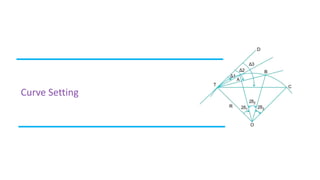
- 28. Correlation Survey Transferring the surface alignment through a vertical shaft is difficult operation in view of the small size of the shaft. Generally, plumb wires are used to transfer directions underground. Essentially, the plumb wires produce a vertical reference plane, and on the surface the plane can be placed in the line of sight; below ground, the line of sight can be sighted into that plane. This is known as co-planing, and the line of sight when established can be used to set up floor or roof stations within the tunnel. Accurate transfer of surface alignment down a vertical shaft using two plumb wires can be achieved by Weisbach triangle method. In Fig. 9.3, p and q are plan positions of the plumb wires P and Q on the ground surface alignment above the tunnel, respectively. A theodolite, reading directly one second, is set up at A’, approximately in line with p and q. In triangle pA'q, the angle pA'q is measured by the method of repetition, and the lengths of sides are also measured correct up to millimeter. The angle pq A’ is also calculated by applying sine rule. Now, the perpendicular distance d of A' from the line qp produced, is calculated from the following expression. The point p and q are joined by a fine thread, and a perpendicular AA' equal to d in length is dropped from A' on the thread. The foot of perpendicular A is the required point on the line qp produced which may be occupied by the theodolite for fixing the points on the floor or roof of the tunnel.