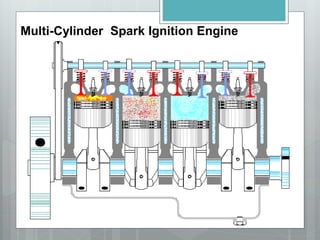
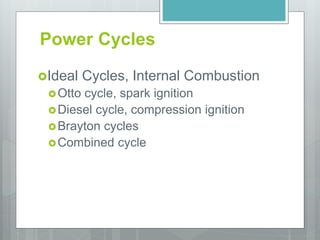
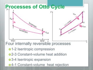
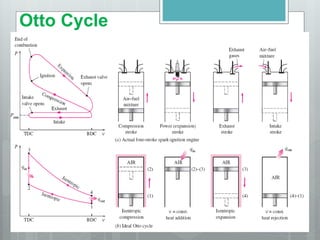
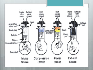
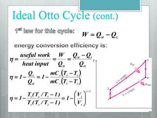
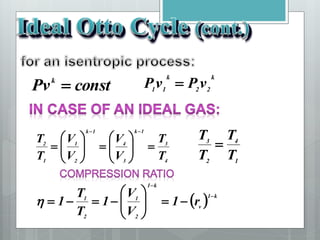
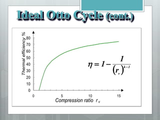
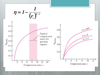
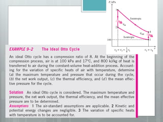
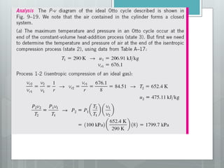
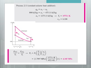
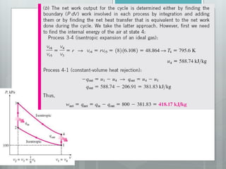
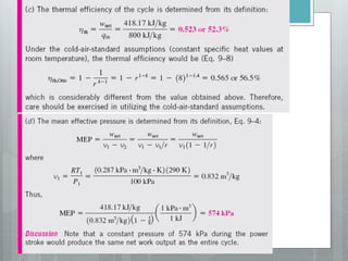
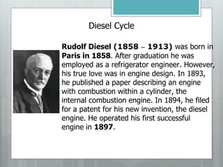
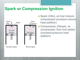
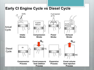
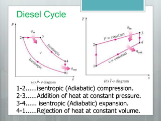
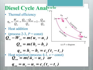
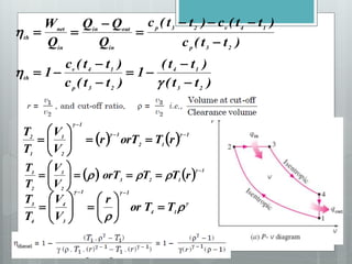
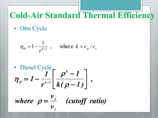
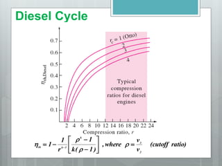
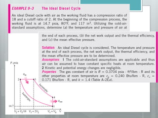
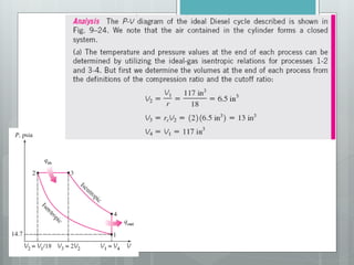
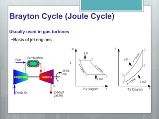
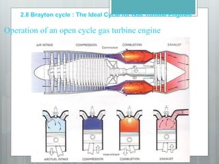
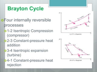
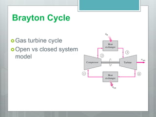
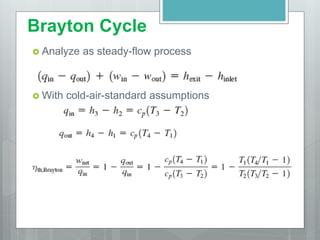
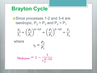
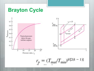
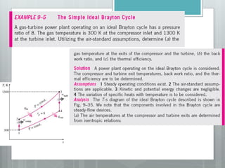
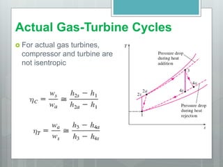
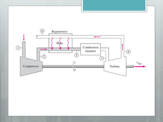
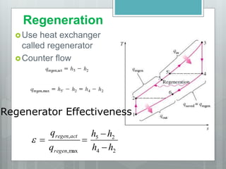
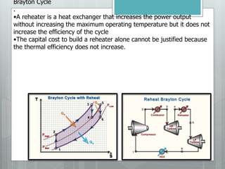
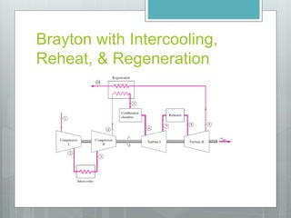
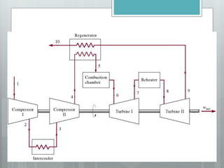
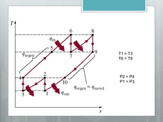
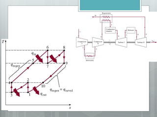
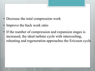
Gas Power Cycles
Multi-Cylinder Spark Ignition Engine
Power Cycles
Ideal Cycles, Internal Combustion
Otto cycle, spark ignition
Diesel cycle, compression ignition
Brayton cycles
Combined cycle
Ideal Cycles Assumptions
Air is the working fluid, circulated in a closed loop,
is an ideal gas
exhaust and air intake are substituted with heat
transfer from the system to the surroundings
combustion is replaced by heat transfer from an
external source to the system
all processes are internally reversible.
gas specific heat is constant
Cycle does not involve any friction
Pipes connecting components have no heat loss
Neglecting changes in kinetic and potential energy
Carnot Cycle
Carnot Cycle
Otto Cycle
Nicolaus August Otto the inventor of
the four-stroke cycle was born on
14th June 1831 in Germany. In
1862 he began first experiments with
four-strokes engines. The first four-
stroke engines is shown. He died on
26th January 1891 in Cologne
• Bottom-dead center (BDC) –
• piston position where volume is maximum
• Top-dead center (TDC) –
• piston position where volume is minimum
• Clearance volume –
• minimum cylinder volume (VTDC = V2)
• Compression ratio (r)
• Displacement volume
2
1
2
1
min
max
v
v
V
V
V
V
V
V
r
TDC
BDC




2
1 V
V
V
V
V TDC
BDC
disp 



Engine Terms
Engine Terms
Mean effective
pressure (MEP)
disp
net
V
W
MEP 
Processes of Otto Cycle
Four internally reversible processes
1-2 Isentropic compression
2-3 Constant-volume heat addition
3-4 Isentropic expansion
4-1 Constant-volume heat rejection
Otto Cycle
Ideal Otto Cycle (cont.)
1
1
2
2
3
2
1
4
1
V
V
1
)
1
T
/
T
(
T
)
1
T
/
T
(
T
1

















 
 
2
3
v
1
4
v
H
L
T
T
mC
T
T
mC
1
Q
Q
1







H
L
H
H
Q
Q
Q
Q
W
input
heat
work
useful 




L
H
Q
Q
W 

const
Pvk

k
2
2
k
1
1
v
P
v
P 
4
3
1
k
3
4
1
k
2
1
1
2
T
T
V
V
V
V
T
T





















  k
1
v
k
1
2
1
2
1
r
1
V
V
1
T
T
1

















1
4
2
3
T
T
T
T

0
10
20
30
40
50
60
70
80
0 5 10 15
Compression ratio r v
Thermal
efficiency
%
  1
k
v
r
1
1 



  1
k
v
r
1
1 



Diesel Cycle
Rudolf Diesel (1858 – 1913) was born in
Paris in 1858. After graduation he was
employed as a refrigerator engineer. However,
his true love was in engine design. In 1893,
he published a paper describing an engine
with combustion within a cylinder, the
internal combustion engine. In 1894, he filed
for a patent for his new invention, the diesel
engine. He operated his first successful
engine in 1897.
Spark or Compression Ignition
 Spark (Otto), air-fuel mixture
compressed (constant-volume
heat addition)
 Compression (Diesel), air
compressed, then fuel added
(constant-pressure heat
addition)
Early CI Engine Cycle vs Diesel Cycle
A
I
R
Combustion
Products
Fuel injected
at TC
Intake
Stroke
FUEL
Fuel/Air
Mixture
Air
TC
BC
Compression
Stroke
Power
Stroke
Exhaust
Stroke
Qin Qout
Compression
Process
Const pressure
heat addition
Process
Expansion
Process
Const volume
heat rejection
Process
Actual
Cycle
Diesel
Cycle
Diesel Cycle
1-2......isentropic (Adiabatic) compression.
2-3......Addition of heat at constant pressure.
3-4...... isentropic (Adiabatic) expansion.
4-1......Rejection of heat at constant volume.
Diesel Cycle Analysis
• Thermal efficiency
• Heat addition
• (process 2-3, P = const)
• Heat rejection (process 4-1, v = const)
in
out
in
out
in
in
net
th
Q
Q
Q
Q
Q
Q
W




 1

)
t
t
(
c
h
h
q
)
h
h
(
m
Q
)
u
u
(
m
W
Q
2
3
p
2
3
in
2
3
in
2
3
23
in









)
t
t
(
c
u
u
q
or
)
u
u
(
m
Q
1
4
v
1
4
out
1
4
out






)
t
t
(
)
t
t
(
1
)
t
t
(
c
)
t
t
(
c
1
)
t
t
(
c
)
t
t
(
c
)
t
t
(
c
Q
Q
Q
Q
W
2
3
1
4
2
3
p
1
4
v
th
2
3
p
1
4
v
2
3
p
in
out
in
in
net
th



















    1
1
2
1
1
2
1
1
2
r
T
orT
r
V
V
T
T 
















    1
1
2
3
2
3
2
3
r
T
T
orT
V
V
T
T 




















 1
4
1
1
3
4
4
3
T
T
or
r
V
V
T
T



















• Otto Cycle
• Diesel Cycle
v
p
k
th c
c
k
r
/
e
wher
,
1
1 1


 

ratio)
(cutoff
v
v
where
,
)
1
(
k
1
r
1
1
2
3
k
1
k
th










 




Cold-Air Standard Thermal Efficiency
Diesel Cycle
ratio)
(cutoff
v
v
where
,
)
1
(
k
1
r
1
1
2
3
k
1
k
th










 




Brayton Cycle (Joule Cycle)
Usually used in gas turbines
•Basis of jet engines
Operation of an open cycle gas turbine engine
2.8 Brayton cycle : The Ideal Cycle for Gas Turbine Engines
Brayton Cycle
Four internally reversible
processes
1-2 Isentropic Compression
(compressor)
2-3 Constant-pressure heat
addition
3-4 Isentropic expansion
(turbine)
4-1 Constant-pressure heat
rejection
Brayton Cycle
Gas turbine cycle
Open vs closed system
model
Brayton Cycle
 Analyze as steady-flow process
 So
 With cold-air-standard assumptions
Brayton Cycle
Since processes 1-2 and 3-4 are
isentropic, P2 = P3 and P4 = P1
where
Brayton Cycle
Actual Gas-Turbine Cycles
 For actual gas turbines,
compressor and turbine are
not isentropic
Regeneration
Regeneration
Use heat exchanger
called regenerator
Counter flow
Regenerator Effectiveness
2
4
2
5
max
,
,
h
h
h
h
q
q
regen
act
regen





Brayton Cycle
.
•A reheater is a heat exchanger that increases the power output
without increasing the maximum operating temperature but it does not
increase the efficiency of the cycle
•The capital cost to build a reheater alone cannot be justified because
the thermal efficiency does not increase.
Brayton with Intercooling,
Reheat, & Regeneration
T1 = T3
T6 = T8
P2 = P4
P1 = P3
• Decrease the total compression work
• Improve the back work ratio
• If the number of compression and expansion stages is
increased, the ideal turbine cycle with intercooling,
reheating and regeneration approaches the Ericsson cycle
55
Example (9.74): Air enters the compressor of a gas turbine at 100 kPa,
300 K. The air is compressed in two stages to 900 kPa, with intercooling to
300 K between the stages at a pressure of 300 kPa. The turbine inlet
temperature is 1480 K and the expansion occurs in two stages, with reheat
to 1420 K between the stages at a pressure of 300 kPa. The compressor and
turbine stage efficiencies are 84 and 82% respectively, The net power
developed is 1.8 W. Determine
(a) The volumetric flow rate entering the cycle.
(b) The thermal efficiency of the cycle.
(c) The back work ratio.
State 1 a b 2 3 c d 4
T (K) 300 300 1480 1420
P (kPa) 100 300 300 900 900 300 300 100
Pr
h (kJ/kg)
56
Example (9.74): The compressor and turbine stage efficiencies are 84 and
82% respectively, The net power developed is 1.8 W. Determine
(a) The thermal efficiency of the cycle.
(b) The back work ratio.
State 1 a b 2 3 c d 4
T (K) 300 300 1480 1420
p (kPa) 100 300 300 900 900 300 300 100
pr 1.3860 1.3860 568.8 478.0
h (kJ/kg) 300.19 300.19 1611.79 1539.44
Find state a, Process 1 – a is
1
1
a
raS r
p
p p
p
   158
.
4
100
300
3860
.
1 







From the table haS = 411.26 kJ/kg
Using the isentropic compressor efficiency:
 
 
1
1
h
h
h
h
a
aS




   
kg
kJ
h
h
h
h aS
a 42
.
432
84
.
0
19
.
300
26
.
411
19
.
300
1
1 







Isentropic compression
57
Example (9.74): The compressor and turbine stage efficiencies are 84 and
82% respectively, The net power developed is 1.8 W. Determine
(a) The thermal efficiency of the cycle.
(b) The back work ratio.
State 1 a b 2 3 c d 4
T (K) 300 300 1480 1420
P (kPa) 100 300 300 900 900 300 300 100
pr 1.3860 1.3860 568.8 478.0
h (kJ/kg) 300.19 432.42 300.19 1611.79 1539.44
Find state a, Process b – 2 is
From the table h2S = 411.26 kJ/kg
2
2
r S rb
b
p
p p
p
   158
.
4
300
900
3860
.
1 







Using the isentropic compressor efficiency:
 
 
b
b
S
h
h
h
h



2
2

   
kg
kJ
h
h
h
h b
S
b 42
.
432
84
.
0
19
.
300
26
.
411
19
.
300
2
2 







Isentropic compression
58
Example (9.74): The compressor and turbine stage efficiencies are 84 and
82% respectively, The net power developed is 1.8 W. Determine
(a) The thermal efficiency of the cycle.
(b) The back work ratio.
State 1 a b 2 3 c d 4
T (K) 300 300 1480 1420
p (kPa) 100 300 300 900 900 300 300 100
pr 1.3860 1.3860 568.8 478.0
h (kJ/kg) 300.19 432.42 300.19 432.42 1611.79 1275.4 1539.44
Find state a, Process 3 – c is
From the table hcS = 1201.5 kJ/kg
3
3
c
rcS r
p
p p
p
   60
.
189
900
300
8
.
568 







Using the isentropic turbine efficiency:
 
 
cS
c
h
h
h
h



3
3

    
kg
kJ
h
h
h
h cS
c 4
.
1275
5
.
1201
79
.
1611
82
.
0
79
.
1611
3
3 





 
Isentropic expansion
State 1 a b 2 3 c d 4
T (K) 300 300 1480 1420
p (kPa) 100 300 300 900 900 300 300 100
pr 1.3860 1.3860 568.8 478.0
h (kJ/kg) 300.19 432.42 300.19 432.42 1611.79 1539.44
State 1 a b 2 3 c d 4
T (K) 300 300 1480 1420
p (kPa) 100 300 300 900 900 300 300 100
pr 1.3860 1.3860 568.8 478.0
h (kJ/kg) 300.19 432.42 300.19 432.42 1611.79 1275.4 1539.44 1216.77
59
Example (9.74): The compressor and turbine stage efficiencies are 84 and
82% respectively, The net power developed is 1.8 W. Determine
State 1 a b 2 3 c d 4
T (K) 300 300 1480 1420
p (kPa) 100 300 300 900 900 300 300 100
pr 1.3860 1.3860 568.8 478.0
h (kJ/kg) 300.19 432.42 300.19 432.42 1611.79 1275.4 1539.44
Find state a, Process d – 4 is
From the table h4S = 1145.94 kJ/kg
4
4
r S rd
d
p
p p
p
   33
.
159
300
100
0
.
478 







Using the isentropic turbine efficiency:
 
 
dS
d
h
h
h
h



4
4

    
kg
kJ
h
h
h
h S
d
d 77
.
1216
94
.
1145
44
.
1539
82
.
0
44
.
1539
4
4 





 
Isentropic expansion
60
Example (9.74): The compressor and turbine stage efficiencies are 84 and
82% respectively, The net power developed is 1.8 W. Determine
(a) The thermal efficiency of the cycle.
(b) The back work ratio.
State 1 a b 2 3 c d 4
T (K) 300 300 1480 1420
p (kPa) 100 300 300 900 900 300 300 100
pr 1.3860 1.3860 568.8 478.0
h (kJ/kg) 300.19 432.42 300.19 432.42 1611.79 1275.4 1539.44 1216.77
Determine the mass flow rate
1 2 1 2 1.8 /
cycle T T C C
W W W W W kJ s
    
       
 
b
a
d
c
cycle
h
h
h
h
h
h
h
h
m
W







 2
1
4
3


kg
kJ
m
Wcycle
6
.
394



1.8 /
4.562 /
394.6 / 394.6 /
cycle
W kJ s
m kg s
kJ kg kJ kg
  
61
Example (9.74): Air enters the compressor of a gas turbine at 100 kPa,
300 K. The air is compressed in two stages to 900 kPa, with intercooling to
300 K between the stages at a pressure of 300 kPa. The turbine inlet
temperature is 1480 K and the expansion occurs in two stages, with reheat
to 1420 K between the stages at a pressure of 300 kPa. The compressor and
turbine stage efficiencies are 84 and 82% respectively, The net power
developed is 1.8 W. Determine
(a) The volumetric flow rate.
(b) The thermal efficiency of the cycle.
(c) The back work ratio.
State 1 a b 2 3 c d 4
T (K) 300 300 1480 1420
p (kPa) 100 300 300 900 900 300 300 100
pr 1.3860 1.3860 568.8 478.0
h (kJ/kg) 300.19 432.42 300.19 432.42 1611.79 1275.4 1539.44 1216.77
s
kg
m 562
.
4


   
  
1
5 2
1
1
0.2870 / 300
V 4.562 /
(10 / )
kJ kg K K
RT
A m kg s
p m

 
 
 
 
 
3
1
V 3.93
m
A
s

62
Example (9.74): Air enters the compressor of a gas turbine at 100 kPa,
300 K. The air is compressed in two stages to 900 kPa, with intercooling to
300 K between the stages at a pressure of 300 kPa. The turbine inlet
temperature is 1480 K and the expansion occurs in two stages, with reheat
to 1420 K between the stages at a pressure of 300 kPa. The compressor and
turbine stage efficiencies are 84 and 82% respectively, The net power
developed is 1.8 W. Determine
(a) The volumetric flow rate.
(b) The thermal efficiency of the cycle.
(c) The back work ratio.
State 1 a b 2 3 c d 4
T (K) 300 300 1480 1420
p (kPa) 100 300 300 900 900 300 300 100
pr 1.3860 1.3860 568.8 478.0
h (kJ/kg) 300.19 432.42 300.19 432.42 1611.79 1275.4 1539.44 1216.77
in
cycle
Q
W




   
 
kg
kJ
h
h
h
h
m
Q c
d
in 41
.
1443
2
3 



 

s
kg
m 562
.
4


2734
.
0
41
.
1443
6
.
394



in
cycle
Q
W



63
Example (9.74): Air enters the compressor of a gas turbine at 100 kPa,
300 K. The air is compressed in two stages to 900 kPa, with intercooling to
300 K between the stages at a pressure of 300 kPa. The turbine inlet
temperature is 1480 K and the expansion occurs in two stages, with reheat
to 1420 K between the stages at a pressure of 300 kPa. The compressor and
turbine stage efficiencies are 84 and 82% respectively, The net power
developed is 1.8 W. Determine
(a) The volumetric flow rate.
(b) The thermal efficiency of the cycle.
(c) The back work ratio.
State 1 a b 2 3 c d 4
T (K) 300 300 1480 1420
p (kPa) 100 300 300 900 900 300 300 100
pr 1.3860 1.3860 568.8 478.0
h (kJ/kg) 300.19 432.42 300.19 432.42 1611.79 1275.4 1539.44 1216.77
C
T
W
bwr
W

s
kg
m 562
.
4


   
   
4
3
2
1
h
h
h
h
h
h
h
h
W
W
bwr
d
c
b
a
T
C










401
.
0
06
.
659
46
.
264


bwr

Gas Power Cycles.ppt

  • 1.
  • 2.
  • 3.
    Power Cycles Ideal Cycles,Internal Combustion Otto cycle, spark ignition Diesel cycle, compression ignition Brayton cycles Combined cycle
  • 4.
    Ideal Cycles Assumptions Airis the working fluid, circulated in a closed loop, is an ideal gas exhaust and air intake are substituted with heat transfer from the system to the surroundings combustion is replaced by heat transfer from an external source to the system all processes are internally reversible. gas specific heat is constant Cycle does not involve any friction Pipes connecting components have no heat loss Neglecting changes in kinetic and potential energy
  • 5.
  • 6.
  • 7.
    Otto Cycle Nicolaus AugustOtto the inventor of the four-stroke cycle was born on 14th June 1831 in Germany. In 1862 he began first experiments with four-strokes engines. The first four- stroke engines is shown. He died on 26th January 1891 in Cologne
  • 8.
    • Bottom-dead center(BDC) – • piston position where volume is maximum • Top-dead center (TDC) – • piston position where volume is minimum • Clearance volume – • minimum cylinder volume (VTDC = V2) • Compression ratio (r) • Displacement volume 2 1 2 1 min max v v V V V V V V r TDC BDC     2 1 V V V V V TDC BDC disp     Engine Terms
  • 9.
    Engine Terms Mean effective pressure(MEP) disp net V W MEP 
  • 10.
    Processes of OttoCycle Four internally reversible processes 1-2 Isentropic compression 2-3 Constant-volume heat addition 3-4 Isentropic expansion 4-1 Constant-volume heat rejection
  • 11.
  • 13.
    Ideal Otto Cycle(cont.) 1 1 2 2 3 2 1 4 1 V V 1 ) 1 T / T ( T ) 1 T / T ( T 1                      2 3 v 1 4 v H L T T mC T T mC 1 Q Q 1        H L H H Q Q Q Q W input heat work useful      L H Q Q W  
  • 14.
    const Pvk  k 2 2 k 1 1 v P v P  4 3 1 k 3 4 1 k 2 1 1 2 T T V V V V T T                       k 1 v k 1 2 1 2 1 r 1 V V 1 T T 1                  1 4 2 3 T T T T 
  • 15.
    0 10 20 30 40 50 60 70 80 0 5 1015 Compression ratio r v Thermal efficiency %   1 k v r 1 1    
  • 16.
      1 k v r 1 1   
  • 22.
    Diesel Cycle Rudolf Diesel(1858 – 1913) was born in Paris in 1858. After graduation he was employed as a refrigerator engineer. However, his true love was in engine design. In 1893, he published a paper describing an engine with combustion within a cylinder, the internal combustion engine. In 1894, he filed for a patent for his new invention, the diesel engine. He operated his first successful engine in 1897.
  • 23.
    Spark or CompressionIgnition  Spark (Otto), air-fuel mixture compressed (constant-volume heat addition)  Compression (Diesel), air compressed, then fuel added (constant-pressure heat addition)
  • 24.
    Early CI EngineCycle vs Diesel Cycle A I R Combustion Products Fuel injected at TC Intake Stroke FUEL Fuel/Air Mixture Air TC BC Compression Stroke Power Stroke Exhaust Stroke Qin Qout Compression Process Const pressure heat addition Process Expansion Process Const volume heat rejection Process Actual Cycle Diesel Cycle
  • 25.
    Diesel Cycle 1-2......isentropic (Adiabatic)compression. 2-3......Addition of heat at constant pressure. 3-4...... isentropic (Adiabatic) expansion. 4-1......Rejection of heat at constant volume.
  • 26.
    Diesel Cycle Analysis •Thermal efficiency • Heat addition • (process 2-3, P = const) • Heat rejection (process 4-1, v = const) in out in out in in net th Q Q Q Q Q Q W      1  ) t t ( c h h q ) h h ( m Q ) u u ( m W Q 2 3 p 2 3 in 2 3 in 2 3 23 in          ) t t ( c u u q or ) u u ( m Q 1 4 v 1 4 out 1 4 out      
  • 27.
    ) t t ( ) t t ( 1 ) t t ( c ) t t ( c 1 ) t t ( c ) t t ( c ) t t ( c Q Q Q Q W 2 3 1 4 2 3 p 1 4 v th 2 3 p 1 4 v 2 3 p in out in in net th                       1 1 2 1 1 2 1 1 2 r T orT r V V T T                      1 1 2 3 2 3 2 3 r T T orT V V T T                       1 4 1 1 3 4 4 3 T T or r V V T T                   
  • 28.
    • Otto Cycle •Diesel Cycle v p k th c c k r / e wher , 1 1 1      ratio) (cutoff v v where , ) 1 ( k 1 r 1 1 2 3 k 1 k th                 Cold-Air Standard Thermal Efficiency
  • 29.
  • 35.
    Brayton Cycle (JouleCycle) Usually used in gas turbines •Basis of jet engines
  • 36.
    Operation of anopen cycle gas turbine engine 2.8 Brayton cycle : The Ideal Cycle for Gas Turbine Engines
  • 37.
    Brayton Cycle Four internallyreversible processes 1-2 Isentropic Compression (compressor) 2-3 Constant-pressure heat addition 3-4 Isentropic expansion (turbine) 4-1 Constant-pressure heat rejection
  • 38.
    Brayton Cycle Gas turbinecycle Open vs closed system model
  • 39.
    Brayton Cycle  Analyzeas steady-flow process  So  With cold-air-standard assumptions
  • 40.
    Brayton Cycle Since processes1-2 and 3-4 are isentropic, P2 = P3 and P4 = P1 where
  • 41.
  • 46.
    Actual Gas-Turbine Cycles For actual gas turbines, compressor and turbine are not isentropic
  • 47.
  • 48.
    Regeneration Use heat exchanger calledregenerator Counter flow Regenerator Effectiveness 2 4 2 5 max , , h h h h q q regen act regen     
  • 49.
    Brayton Cycle . •A reheateris a heat exchanger that increases the power output without increasing the maximum operating temperature but it does not increase the efficiency of the cycle •The capital cost to build a reheater alone cannot be justified because the thermal efficiency does not increase.
  • 50.
  • 52.
    T1 = T3 T6= T8 P2 = P4 P1 = P3
  • 54.
    • Decrease thetotal compression work • Improve the back work ratio • If the number of compression and expansion stages is increased, the ideal turbine cycle with intercooling, reheating and regeneration approaches the Ericsson cycle
  • 55.
    55 Example (9.74): Airenters the compressor of a gas turbine at 100 kPa, 300 K. The air is compressed in two stages to 900 kPa, with intercooling to 300 K between the stages at a pressure of 300 kPa. The turbine inlet temperature is 1480 K and the expansion occurs in two stages, with reheat to 1420 K between the stages at a pressure of 300 kPa. The compressor and turbine stage efficiencies are 84 and 82% respectively, The net power developed is 1.8 W. Determine (a) The volumetric flow rate entering the cycle. (b) The thermal efficiency of the cycle. (c) The back work ratio. State 1 a b 2 3 c d 4 T (K) 300 300 1480 1420 P (kPa) 100 300 300 900 900 300 300 100 Pr h (kJ/kg)
  • 56.
    56 Example (9.74): Thecompressor and turbine stage efficiencies are 84 and 82% respectively, The net power developed is 1.8 W. Determine (a) The thermal efficiency of the cycle. (b) The back work ratio. State 1 a b 2 3 c d 4 T (K) 300 300 1480 1420 p (kPa) 100 300 300 900 900 300 300 100 pr 1.3860 1.3860 568.8 478.0 h (kJ/kg) 300.19 300.19 1611.79 1539.44 Find state a, Process 1 – a is 1 1 a raS r p p p p    158 . 4 100 300 3860 . 1         From the table haS = 411.26 kJ/kg Using the isentropic compressor efficiency:     1 1 h h h h a aS         kg kJ h h h h aS a 42 . 432 84 . 0 19 . 300 26 . 411 19 . 300 1 1         Isentropic compression
  • 57.
    57 Example (9.74): Thecompressor and turbine stage efficiencies are 84 and 82% respectively, The net power developed is 1.8 W. Determine (a) The thermal efficiency of the cycle. (b) The back work ratio. State 1 a b 2 3 c d 4 T (K) 300 300 1480 1420 P (kPa) 100 300 300 900 900 300 300 100 pr 1.3860 1.3860 568.8 478.0 h (kJ/kg) 300.19 432.42 300.19 1611.79 1539.44 Find state a, Process b – 2 is From the table h2S = 411.26 kJ/kg 2 2 r S rb b p p p p    158 . 4 300 900 3860 . 1         Using the isentropic compressor efficiency:     b b S h h h h    2 2      kg kJ h h h h b S b 42 . 432 84 . 0 19 . 300 26 . 411 19 . 300 2 2         Isentropic compression
  • 58.
    58 Example (9.74): Thecompressor and turbine stage efficiencies are 84 and 82% respectively, The net power developed is 1.8 W. Determine (a) The thermal efficiency of the cycle. (b) The back work ratio. State 1 a b 2 3 c d 4 T (K) 300 300 1480 1420 p (kPa) 100 300 300 900 900 300 300 100 pr 1.3860 1.3860 568.8 478.0 h (kJ/kg) 300.19 432.42 300.19 432.42 1611.79 1275.4 1539.44 Find state a, Process 3 – c is From the table hcS = 1201.5 kJ/kg 3 3 c rcS r p p p p    60 . 189 900 300 8 . 568         Using the isentropic turbine efficiency:     cS c h h h h    3 3       kg kJ h h h h cS c 4 . 1275 5 . 1201 79 . 1611 82 . 0 79 . 1611 3 3         Isentropic expansion State 1 a b 2 3 c d 4 T (K) 300 300 1480 1420 p (kPa) 100 300 300 900 900 300 300 100 pr 1.3860 1.3860 568.8 478.0 h (kJ/kg) 300.19 432.42 300.19 432.42 1611.79 1539.44
  • 59.
    State 1 ab 2 3 c d 4 T (K) 300 300 1480 1420 p (kPa) 100 300 300 900 900 300 300 100 pr 1.3860 1.3860 568.8 478.0 h (kJ/kg) 300.19 432.42 300.19 432.42 1611.79 1275.4 1539.44 1216.77 59 Example (9.74): The compressor and turbine stage efficiencies are 84 and 82% respectively, The net power developed is 1.8 W. Determine State 1 a b 2 3 c d 4 T (K) 300 300 1480 1420 p (kPa) 100 300 300 900 900 300 300 100 pr 1.3860 1.3860 568.8 478.0 h (kJ/kg) 300.19 432.42 300.19 432.42 1611.79 1275.4 1539.44 Find state a, Process d – 4 is From the table h4S = 1145.94 kJ/kg 4 4 r S rd d p p p p    33 . 159 300 100 0 . 478         Using the isentropic turbine efficiency:     dS d h h h h    4 4       kg kJ h h h h S d d 77 . 1216 94 . 1145 44 . 1539 82 . 0 44 . 1539 4 4         Isentropic expansion
  • 60.
    60 Example (9.74): Thecompressor and turbine stage efficiencies are 84 and 82% respectively, The net power developed is 1.8 W. Determine (a) The thermal efficiency of the cycle. (b) The back work ratio. State 1 a b 2 3 c d 4 T (K) 300 300 1480 1420 p (kPa) 100 300 300 900 900 300 300 100 pr 1.3860 1.3860 568.8 478.0 h (kJ/kg) 300.19 432.42 300.19 432.42 1611.79 1275.4 1539.44 1216.77 Determine the mass flow rate 1 2 1 2 1.8 / cycle T T C C W W W W W kJ s                b a d c cycle h h h h h h h h m W         2 1 4 3   kg kJ m Wcycle 6 . 394    1.8 / 4.562 / 394.6 / 394.6 / cycle W kJ s m kg s kJ kg kJ kg   
  • 61.
    61 Example (9.74): Airenters the compressor of a gas turbine at 100 kPa, 300 K. The air is compressed in two stages to 900 kPa, with intercooling to 300 K between the stages at a pressure of 300 kPa. The turbine inlet temperature is 1480 K and the expansion occurs in two stages, with reheat to 1420 K between the stages at a pressure of 300 kPa. The compressor and turbine stage efficiencies are 84 and 82% respectively, The net power developed is 1.8 W. Determine (a) The volumetric flow rate. (b) The thermal efficiency of the cycle. (c) The back work ratio. State 1 a b 2 3 c d 4 T (K) 300 300 1480 1420 p (kPa) 100 300 300 900 900 300 300 100 pr 1.3860 1.3860 568.8 478.0 h (kJ/kg) 300.19 432.42 300.19 432.42 1611.79 1275.4 1539.44 1216.77 s kg m 562 . 4          1 5 2 1 1 0.2870 / 300 V 4.562 / (10 / ) kJ kg K K RT A m kg s p m            3 1 V 3.93 m A s 
  • 62.
    62 Example (9.74): Airenters the compressor of a gas turbine at 100 kPa, 300 K. The air is compressed in two stages to 900 kPa, with intercooling to 300 K between the stages at a pressure of 300 kPa. The turbine inlet temperature is 1480 K and the expansion occurs in two stages, with reheat to 1420 K between the stages at a pressure of 300 kPa. The compressor and turbine stage efficiencies are 84 and 82% respectively, The net power developed is 1.8 W. Determine (a) The volumetric flow rate. (b) The thermal efficiency of the cycle. (c) The back work ratio. State 1 a b 2 3 c d 4 T (K) 300 300 1480 1420 p (kPa) 100 300 300 900 900 300 300 100 pr 1.3860 1.3860 568.8 478.0 h (kJ/kg) 300.19 432.42 300.19 432.42 1611.79 1275.4 1539.44 1216.77 in cycle Q W           kg kJ h h h h m Q c d in 41 . 1443 2 3        s kg m 562 . 4   2734 . 0 41 . 1443 6 . 394    in cycle Q W   
  • 63.
    63 Example (9.74): Airenters the compressor of a gas turbine at 100 kPa, 300 K. The air is compressed in two stages to 900 kPa, with intercooling to 300 K between the stages at a pressure of 300 kPa. The turbine inlet temperature is 1480 K and the expansion occurs in two stages, with reheat to 1420 K between the stages at a pressure of 300 kPa. The compressor and turbine stage efficiencies are 84 and 82% respectively, The net power developed is 1.8 W. Determine (a) The volumetric flow rate. (b) The thermal efficiency of the cycle. (c) The back work ratio. State 1 a b 2 3 c d 4 T (K) 300 300 1480 1420 p (kPa) 100 300 300 900 900 300 300 100 pr 1.3860 1.3860 568.8 478.0 h (kJ/kg) 300.19 432.42 300.19 432.42 1611.79 1275.4 1539.44 1216.77 C T W bwr W  s kg m 562 . 4           4 3 2 1 h h h h h h h h W W bwr d c b a T C           401 . 0 06 . 659 46 . 264   bwr