Gas turbines have three main parts - an air compressor, combustion chamber, and turbine. The air compressor increases the pressure of air that is mixed with fuel in the combustion chamber and ignited. This powers the turbine, which can generate mechanical power or thrust. There are two main types - open cycle gas turbines that exhaust air to the atmosphere, and closed cycle gas turbines that recirculate the working fluid through a cooler before returning it to the compressor. Methods to improve gas turbine efficiency include intercooling the compressed air between compression stages, reheating the gas before a secondary expansion turbine, and regenerating heat from the exhaust to preheat the incoming compressed air.
A gas turbine, also called a combustion turbine, is a type of internal combustion engine. It has an upstream rotating compressor coupled toa downstream turbine, and a combustion chamber in-between. Energy is added to the gas stream in the combustor, where fuel is mixed with air and ignited. In the high-pressure environment of the combustor, combustion of the fuel increases the temperature. The products of the combustion are forced into the turbine section
Visit https://www.topicsforseminar.com to Download
A steam turbine is a prime mover in which the potential energy of the steam is transformed into kinetic energy and later in its turn is transformed into the mechanical energy of rotation of the turbine shaft
Theoretical cycle based on the actual properties of the cylinder contents is called the fuel air cycle.
The fuel air cycle takes into consideration the following.
The ACTUAL COMPOSITION of the cylinder contents.
The VARIATION OF SPECIFIC HEAT of the gases in the cylinder.
The DISSOCIATION EFFECT.
The VARIATION IN THE NUMBER OF MOLES present in the cylinder as the pressure and temperature change
Compressors are mechanical devices used for increasing the pressure of a gas. Compressors used for
producing high pressure air are called air compressors. Air is drawn from the atmosphere by suction process, which is then compressed to the required pressure and delivered to the receiver
Simple description about gas turbine. Where you are going to know about its classification,advantages and disadvantages also.Here also you can find-out where it is actually usages.
(
ME- 495 Laboratory Exercise
–
Number 1
– Brayton Cycle -
ME Department, SDSU
-
Nourollahi
) (
11
)Brayton Cycle (Gas Turbine Power Cycle)
Objective
The objective of this lab exercise is to gain practical knowledge of the Brayton cycle. The Brayton cycle illustrates the cold-air-standard assumption (constant specific heats at room temperature) model of a gas turbine power cycle. A portable propulsion laboratory[footnoteRef:1] containing a Model SR-30 turbojet is used in this exercise. The student shall apply the basic equations for Brayton cycle analysis by using empirical measurements at different points in the Brayton cycle. [1: Manufactured by Turbine Technologies Ltd. Called TTL Mini-Lab]
Figure 1: TTL Mini-Lab manufactured by Turbine Technologies Ltd. (TTL)Background
A simple gas turbine engine has three main components: a compressor section, a combustion chamber and a turbine section. Basic operation entails drawing atmospheric air into the compressor where it is heated through compression. The compressed and heated air is mixed with fuel in the combustion chamber. The air/fuel mixture burns at constant pressure in the combustion chamber. The resulting hot gas is directed to the turbine section where it expands. As the gas expands it produces a thrust reaction and performs work by turning the turbine. The turbine is connected to the compressor by a shaft. The resulting shaft work is used to drive the compressor and auxiliary power supplies.
The gas turbine has wide spread application. Most notably, it is used to power and propel aircraft and large ships. In some cases only the thrust resulting from the expanding gas exiting the turbine is used for propulsion and the shaft work is used to drive the compressor and power electrical systems. In turbo-fan engines some of the shaft work is used to drive a large fan that aids in propulsion. In other applications, such as helicopters and ships, propulsion is achieved through the shaft work, which is used to drive transmission/gear boxes that are connected to the rotor blades or propeller, respectively. Gas turbines are also commonly used to drive large electrical generators in power plant applications.Theory
The Brayton cycle consists of four basic processes (see Figure3 & 4). Low-pressure air is drawn into the compressor section and undergoes isentropic compression. Next, the heated and compressed air is combined with fuel in the combustion chamber. The air/fuel mixture experiences reversible constant pressure heat addition. The resulting hot gas enters the turbine section where it undergoes isentropic expansion. To complete the cycle (the exhaust and intake in the open cycle) the gas experiences reversible constant pressure heat rejection.
Thermodynamics and the First Law of Thermodynamics determine the overall energy transfer. The following assumptions are used when analyzing the gas turbine cycles:
1. The working fluid (air) is an ideal gas throughout the cycle.
2. The combust ...
Gas Turbine Powerplants Gas Turbine Powerplants Gas Turbine Powerplants Gas Turbine Powerplants Gas Turbine Powerplants Gas Turbine Powerplants Gas Turbine Powerplants Gas Turbine Powerplants Gas Turbine Powerplants Gas Turbine Powerplants Gas Turbine Powerplants Gas Turbine Powerplants Gas Turbine Powerplants Gas Turbine Powerplants Gas Turbine Powerplants Gas Turbine Powerplants Gas Turbine Powerplants Gas Turbine Powerplants Gas Turbine Powerplants Gas Turbine Powerplants Gas Turbine Powerplants Gas Turbine Powerplants Gas Turbine Powerplants Gas Turbine Powerplants Gas Turbine Powerplants Gas Turbine Powerplants Gas Turbine Powerplants Gas Turbine Powerplants Gas Turbine Powerplants Gas Turbine Powerplants Gas Turbine Powerplants Gas Turbine Powerplants Gas Turbine Powerplants Gas Turbine Powerplants Gas Turbine Powerplants Gas Turbine Powerplants Gas Turbine Powerplants Gas Turbine Powerplants Gas Turbine Powerplants Gas Turbine Powerplants
Vaccine management system project report documentation..pdfKamal Acharya
The Division of Vaccine and Immunization is facing increasing difficulty monitoring vaccines and other commodities distribution once they have been distributed from the national stores. With the introduction of new vaccines, more challenges have been anticipated with this additions posing serious threat to the already over strained vaccine supply chain system in Kenya.
Quality defects in TMT Bars, Possible causes and Potential Solutions.PrashantGoswami42
Maintaining high-quality standards in the production of TMT bars is crucial for ensuring structural integrity in construction. Addressing common defects through careful monitoring, standardized processes, and advanced technology can significantly improve the quality of TMT bars. Continuous training and adherence to quality control measures will also play a pivotal role in minimizing these defects.
Courier management system project report.pdfKamal Acharya
It is now-a-days very important for the people to send or receive articles like imported furniture, electronic items, gifts, business goods and the like. People depend vastly on different transport systems which mostly use the manual way of receiving and delivering the articles. There is no way to track the articles till they are received and there is no way to let the customer know what happened in transit, once he booked some articles. In such a situation, we need a system which completely computerizes the cargo activities including time to time tracking of the articles sent. This need is fulfilled by Courier Management System software which is online software for the cargo management people that enables them to receive the goods from a source and send them to a required destination and track their status from time to time.
CFD Simulation of By-pass Flow in a HRSG module by R&R Consult.pptxR&R Consult
CFD analysis is incredibly effective at solving mysteries and improving the performance of complex systems!
Here's a great example: At a large natural gas-fired power plant, where they use waste heat to generate steam and energy, they were puzzled that their boiler wasn't producing as much steam as expected.
R&R and Tetra Engineering Group Inc. were asked to solve the issue with reduced steam production.
An inspection had shown that a significant amount of hot flue gas was bypassing the boiler tubes, where the heat was supposed to be transferred.
R&R Consult conducted a CFD analysis, which revealed that 6.3% of the flue gas was bypassing the boiler tubes without transferring heat. The analysis also showed that the flue gas was instead being directed along the sides of the boiler and between the modules that were supposed to capture the heat. This was the cause of the reduced performance.
Based on our results, Tetra Engineering installed covering plates to reduce the bypass flow. This improved the boiler's performance and increased electricity production.
It is always satisfying when we can help solve complex challenges like this. Do your systems also need a check-up or optimization? Give us a call!
Work done in cooperation with James Malloy and David Moelling from Tetra Engineering.
More examples of our work https://www.r-r-consult.dk/en/cases-en/
NO1 Uk best vashikaran specialist in delhi vashikaran baba near me online vas...Amil Baba Dawood bangali
Contact with Dawood Bhai Just call on +92322-6382012 and we'll help you. We'll solve all your problems within 12 to 24 hours and with 101% guarantee and with astrology systematic. If you want to take any personal or professional advice then also you can call us on +92322-6382012 , ONLINE LOVE PROBLEM & Other all types of Daily Life Problem's.Then CALL or WHATSAPP us on +92322-6382012 and Get all these problems solutions here by Amil Baba DAWOOD BANGALI
#vashikaranspecialist #astrologer #palmistry #amliyaat #taweez #manpasandshadi #horoscope #spiritual #lovelife #lovespell #marriagespell#aamilbabainpakistan #amilbabainkarachi #powerfullblackmagicspell #kalajadumantarspecialist #realamilbaba #AmilbabainPakistan #astrologerincanada #astrologerindubai #lovespellsmaster #kalajaduspecialist #lovespellsthatwork #aamilbabainlahore#blackmagicformarriage #aamilbaba #kalajadu #kalailam #taweez #wazifaexpert #jadumantar #vashikaranspecialist #astrologer #palmistry #amliyaat #taweez #manpasandshadi #horoscope #spiritual #lovelife #lovespell #marriagespell#aamilbabainpakistan #amilbabainkarachi #powerfullblackmagicspell #kalajadumantarspecialist #realamilbaba #AmilbabainPakistan #astrologerincanada #astrologerindubai #lovespellsmaster #kalajaduspecialist #lovespellsthatwork #aamilbabainlahore #blackmagicforlove #blackmagicformarriage #aamilbaba #kalajadu #kalailam #taweez #wazifaexpert #jadumantar #vashikaranspecialist #astrologer #palmistry #amliyaat #taweez #manpasandshadi #horoscope #spiritual #lovelife #lovespell #marriagespell#aamilbabainpakistan #amilbabainkarachi #powerfullblackmagicspell #kalajadumantarspecialist #realamilbaba #AmilbabainPakistan #astrologerincanada #astrologerindubai #lovespellsmaster #kalajaduspecialist #lovespellsthatwork #aamilbabainlahore #Amilbabainuk #amilbabainspain #amilbabaindubai #Amilbabainnorway #amilbabainkrachi #amilbabainlahore #amilbabaingujranwalan #amilbabainislamabad
Industrial Training at Shahjalal Fertilizer Company Limited (SFCL)MdTanvirMahtab2
This presentation is about the working procedure of Shahjalal Fertilizer Company Limited (SFCL). A Govt. owned Company of Bangladesh Chemical Industries Corporation under Ministry of Industries.
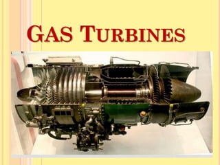
2. Gas Turbines
A gas turbine is a machine delivering mechanical power
or thrust. It does this using a gaseous working fluid.
The mechanical power generated can be used by, for
example, an industrial device.
The outgoing gaseous fluid can be used to generate
thrust. In the gas turbine, there is a continuous flow of
the working fluid. Its efficiency is 20 to 30%
Major Applications of Gas Turbine
1. Aviation(self contained, light weight, don’t require cooling)
2. Power Generation
3. Oil and Gas industry
4. Marine propulsion
3. Working
Air is compressed(squeezed) to high pressure by a
compressor.
Then fuel and compressed air are mixed in a
combustion chamber and ignited.
Hot gases are given off, which spin the turbine.
Gas turbines burn fuels such as oil, natural gas and
pulverized(powdered) coal.
4. Gas turbines have three main parts:
1. Air compressor
2. Combustion chamber
3. Turbine
5. Air compressor:
The air compressor and turbine are mounted at
either end on a common shaft, with the
combustion chamber between them.
Gas turbines are not self starting. A starting
motor is used.
The air compressor sucks in air and compresses
it, thereby increasing its pressure.
6. Combustion chamber:
In the combustion chamber, the compressed air
combines with fuel and the resulting mixture is
burnt.
The greater the pressure of air, the better the
fuel air mixture burns.
Modern gas turbines usually use liquid fuel, but
they may also use gaseous fuel, natural gas or
gas produced artificially by gasification of a
solid fuel
7. Turbine:
Hot gases move through a multistage gas
turbine.
Like in steam turbine, the gas turbine also has
stationary and moving blades.
The stationary blades
guide the moving gases to the rotor blades
adjust its velocity.
shaft of the turbine is coupled to a generator
8. Working Cycle:
Brayton cycle is the ideal cycle for gas-turbine.
1-2 isentropic compression (in compressor)
2-3 Const. pressure heat-addition (in combustion chamber)
3-4 isentropic expansion (in turbine)
4-1 const. pressure heat rejection (exhaust)
9. Thermal Efficiency for Closed Brayton Cycle:
For unit mass of air,
Heat supplied during process 2 – 3,1ݍ = 𝐶𝑃 (𝑇3 − 𝑇2)
Heat rejected during process 4 – 1, 2ݍ = 𝐶𝑃 (𝑇4 − 𝑇1)
Work done, 𝑊 = 1ݍ − 2ݍ
𝑊 = 𝐶𝑃 (𝑇3 − 𝑇2) − CP(T4 − T1)
Thermal efficiency, 𝜂 =
Work done
Heat Supplied
=
CP (T3 − T2) − CP(T4 − T1)
CP (T3 − T2)
=1 −
(T4 − T1)
(T3 − T2)
-------eqn.(1)
Pressure ratio, ݎ =
P2
P1
=
P3
P4
For isentropic compression process (1 – 2),
T2
T1
= (P2/P1)(𝛾−1)/𝛾
= (rp)(𝛾−1)/𝛾
∴ T2= T1 (rp)(𝛾−1)/𝛾 -----------(2)
11. Types of Gas Turbines:
1. Open Cycle Gas Turbine
2. Closed Cycle Gas Turbine
12. Open Cycle Gas Turbine
1-2 Isentropic compression in compressor;
2-3 Constant-pressure heat addition in combustion
chamber;
3-4 Isentropic expansion in the turbine;
13. Open Cycle Gas Turbine
It consists of a compressor, combustion chamber and a
turbine. The compressor takes in ambient air and raises
its pressure. Heat is added to the air in combustion
chamber by burning the fuel and raises its temperature.
The heated gases coming out of combustion chamber are
then passed to the turbine where it expands doing
mechanical work.
14. Efficiency of compressor,
𝜂ܿ =
Isentropic Compression work
Actual Compression work
=
CP (T2 − T1)
CP (T2′ − T1)
=
(T2 − T1)
(T2′ − T1)
Efficiency of turbine,
𝜂t =
Actual turbine work
Isentropic turbine work
=
CP (T3−T4′)
CP (T3−T4)
=
(T3−T4′)
(T3−T4)
Actual Compression work, Wc = CP (T2' − T1)
Actual turbine work, Wt = CP (T3 − T4')
Actual net work = Wc − Wt = CP[(T3 − T4') − (T2' − T1)]
Thermal efficiency, 𝜂 =
Net Work
Heat Supplied
=
CP[(T3 − T4') − (T2' − T1)]
CP (T3 – T2' )
𝜂 =
(T3 −T2′) − (T4′− T1)
(T3 – T2′ )
𝜂 = 1 −
T4′ − T1
T3 – T2′
Turbine work ratio =
Wt
Wc
15. Closed Cycle Gas Turbine
1-2 Isentropic compression in compressor;
2-3 Constant-pressure heat addition in combustion
chamber;
3-4 Isentropic expansion in the turbine;
4-1 Constant pressure heat rejection in heat exchanger
16. Closed Cycle Gas Turbine
It uses air as working medium. In closed cycle gas turbine plant, the
working fluid (air or any other suitable gas) coming out from
compressor is heated in a heater by an external source at constant
pressure.
The high temperature and high-pressure air coming out from the
external heater is passed through the gas turbine.
The fluid coming out from the turbine is cooled to its original
temperature in the cooler using external cooling source before
passing to the compressor.
The working fluid is continuously used in the system without its
change of phase and the required heat is given to the working fluid
in the heat exchanger.
17. Compare Open cycle and Closed cycle Gas turbines
S no. Open cycle gas turbine Closed cycle gas turbine
1 Low thermal efficiency High thermal efficiency
2 Working fluid is replaced
continuously circulated
Working fluid is circulated
continuously
3 High cost fuels are used Low cost fuels can be used
4 Turbine blade wear is high
due to contamination of air in
combustion chamber
Turbine blade wear is low as gas does
not get contaminated while flowing
through combustion chamber
5 Suitable for moving
applications
Suitable for stationary installations
6 Maintenance cost is low Maintenance cost is high
7 Low power to weight ratio High power to weight ratio
8 System is simple System is complex
18. Methods of improving thermal
efficiency of open cycle gas turbine
1. Intercooling
2. 2. Reheating
3. 3. Regeneration
19. Intercooling
A compressor in a gas turbine cycle utilizes the major
percentage of power developed by the gas turbine. The
work required by the compressor can be reduced by
compressing the air in two stages and incorporating an
intercooler between the two as shown in Fig.
1-2’ Low Pressure
Compression
2’-3 Intercooling
3-4’ High Pressure
Compression
4’-5 Heat addition in
combustion chamber
5-6’ Expansion in turbine
20. Work input (with intercooling),
= 𝐶′2𝑇( − 𝑇1) + 𝐶′4𝑇( − 𝑇3) -------(1)
Work input (without intercooling),
= 𝐶𝐿𝑇( ′ − 𝑇1) = 𝐶2𝑇( ′ − 𝑇1) + 𝐶′𝐿𝑇( − 𝑇2′) ------(2)
By comparing the equations (1) and (2) it can be observed that the work
input with intercooling is less than the work input without intercooling,
as 𝐶4𝑇( ′ − 𝑇3) < 𝐶𝐿𝑇( ′ − 𝑇2 ′)
21. Reheating
The output of gas turbine can be improved by
expanding the gasses in two stages with a reheater
between the two turbines.
The H.P. turbine drives the compressor and the LP
turbine provides useful power output.
1-2’ Compression
in compressor
2’-3 Heat addition in CC
3-4’ Expansion in HP turbine
4’-5 Heat addition in
reheater
5-6’ Expansion in LP turbine
22. Work output (with reheating) = 𝐶3𝑇( − 𝑇4′) + 𝐶5𝑇( − 𝑇6′)------(a)
Work output (without reheating) = 𝐶3𝑇( − 𝑇𝐿′)
=𝐶3𝑇( − 𝑇4′) + 𝐶′4𝑇( − 𝑇𝐿′) ------(b)
Since the pressure lines diverse to the right on T-s diagram, it can be
seen that the temperature difference (𝑇5 − 𝑇6′) is always greater
than (𝑇4′ − 𝑇𝐿′). So the reheating increases the net work.
23. Regeneration
The temperature of exhaust gases leaving the turbine of a gas
turbine engine is considerably higher than the temperature of air
delivered by the compressor.
Therefore, high pressure air leaving the compressor can be heated
by hot exhaust gases, thereby reducing the mass of fuel supplied in
the combustion chamber. Hence the thermal efficiency can be
increased.
The heat exchanger used to transfer the heat from exhaust gases to
compressed air is known as regenerator.
24. 1-2’ ---- Compression in compressor
2’-3 ---- Heat addition into the compressed air during its passage
through the heat exchanger
3-4 ---- Heat addition in the combustion chamber
4-5’ ---- Expansion in turbine
5’-6 ---- Heat rejection in heat exchanger to the compressed air
25. The effectiveness of the heat exchanger is given by,
ε = ݁ݏܽ݁ݎܿ݊ܫ ݅݊ ݁݊ݐℎ݈ܽݕ ݎ݁ ݇݃ ݂ ܽ݅ݎ
݈ܾ݈݁ܽ݅ܽݒܣ ݅݊ܿ݁ݏܽ݁ݎ ݅݊ ݁݊ݐℎ݈ܽݕ ݎ݁ ݇݃ ݂ ܽ݅ݎ
=
T3−T2′
T5′− T2′