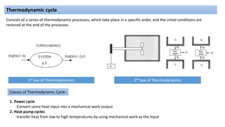
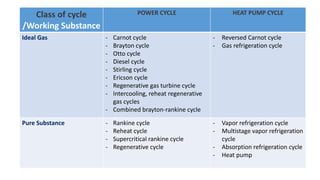
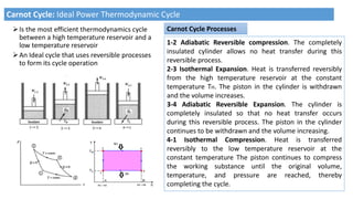
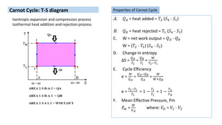
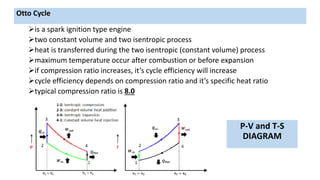
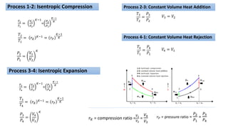
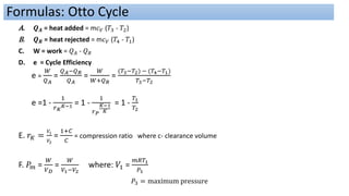
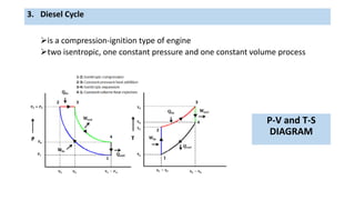
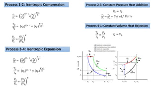
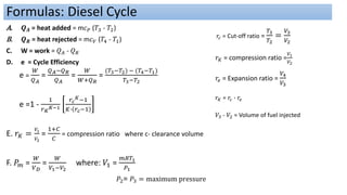
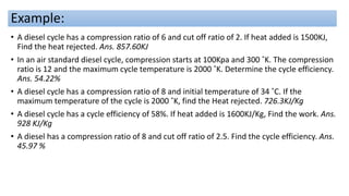
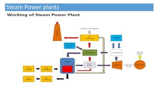
SlideShare a Scribd company logo
THERMODYNAMIC CYCLES
2nd law of Thermodynamics
1st law of Thermodynamics
Consists of a series of thermodynamic processes, which take place in a specific order, and the initial conditions are
restored at the end of the processes.
Thermodynamic cycle
Classes of Thermodynamic Cycle:
1. Power cycle
-Convert some heat input into a mechanical work output
2. Heat pump cycles
-transfer heat from low to high temperatures by using mechanical work as the input
Class of cycle
/Working Substance
POWER CYCLE HEAT PUMP CYCLE
Ideal Gas - Carnot cycle
- Brayton cycle
- Otto cycle
- Diesel cycle
- Stirling cycle
- Ericson cycle
- Regenerative gas turbine cycle
- Intercooling, reheat regenerative
gas cycles
- Combined brayton-rankine cycle
- Reversed Carnot cycle
- Gas refrigeration cycle
Pure Substance - Rankine cycle
- Reheat cycle
- Supercritical rankine cycle
- Regenerative cycle
- Vapor refrigeration cycle
- Multistage vapor refrigeration
cycle
- Absorption refrigeration cycle
- Heat pump
Carnot Cycle: Ideal Power Thermodynamic Cycle
Is the most efficient thermodynamics cycle
between a high temperature reservoir and a
low temperature reservoir
An Ideal cycle that uses reversible processes
to form its cycle operation
1-2 Adiabatic Reversible compression. The completely
insulated cylinder allows no heat transfer during this
reversible process.
2-3 Isothermal Expansion. Heat is transferred reversibly
from the high temperature reservoir at the constant
temperature TH. The piston in the cylinder is withdrawn
and the volume increases.
3-4 Adiabatic Reversible Expansion. The cylinder is
completely insulated so that no heat transfer occurs
during this reversible process. The piston in the cylinder
continues to be withdrawn and the volume increasing.
4-1 Isothermal Compression. Heat is transferred
reversibly to the low temperature reservoir at the
constant temperature The piston continues to compress
the working substance until the original volume,
temperature, and pressure are reached, thereby
completing the cycle.
Carnot Cycle Processes
A. 𝑄𝐴 = heat added = 𝑇2 (𝑆4 - 𝑆1)
B. 𝑄𝑅 = heat rejected = 𝑇1 (𝑆4 - 𝑆1)
C. W = net work output = 𝑄𝐴 - 𝑄𝑅
W = (𝑇2 - 𝑇1) (𝑆4 - 𝑆1)
D. Change in entropy
ΔS =
𝑄𝐴
𝑇2
=
𝑄𝑅
𝑇1
=
𝑊
𝑇2−𝑇1
E. Cycle Efficiency
e =
𝑊
𝑄𝐴
=
𝑄𝐴−𝑄𝑅
𝑄𝐴
=
𝑊
𝑊+𝑄𝑅
e =
𝑇2−𝑇1
𝑇2
= 1 −
𝑇1
𝑇2
= 1 −
𝑇𝐿
𝑇𝐻
F. Mean Effective Pressure, Pm
𝑃𝑚 =
𝑊
𝑉𝐷
where: 𝑉𝐷 = 𝑉1 - 𝑉2
Properties of Carnot Cycle
Carnot Cycle: T-S diagram
Isentropic expansion and compression process
Isothermal heat addition and rejection process
Learning Exercises
1. A carnot engine requires 35 KJ/sec from the hot source. The engine produces 15kw of power and
temperature of the sink is 26 degree Celsius. What is the temperature of the hot source? Ans. 250.5 ˚ C
2. The maximum thermal efficiency possible for a power cycle operating between 1200 ˚F and 225 ˚F
is_____? Ans. 58.7%
3. A carnot engine operating on air accepts 50KJ/Kg of heat and rejects 20KJ/Kg. Calculate the high and low
reservoir temperature if the maximum specific volume is 10m^3/kg and the pressure after isothermal
expansion is 200Kpa. ans. 432.2 and 9.1 ˚ C
4. A Carnot engine receives 130Btu of heat from a hot reservoir at 700 ˚F and rejects 49Btu of heat.
Calculate the temperature of the cold reservoir. Ans. -22.77 ˚F
5. A carnot engine operates between two temperature reservoirs maintained at 200 ˚C and 20˚ C,
respectively. If the desired output of the engine is 15KW, determine the heat transfer from the high
temperature reservoir and heat transfer to the low-temperature reservoirs. Ans. 39.41KW, 24.41KW
6. A carnot heat engine produces 10Hp by transferring energy between two reservoirs at 40 ˚ F and 212 ˚ F.
Calculate the rate of heat transfer from the high temperature reservoir. Ans. 1656.56 Btu/min
Internal Combustion Engine
Is a heat engine which converts the heat energy released by the
combustion of the fuel inside the engine cylinder, into mechanical work.
Classification of I.C. Engines
1. Nature of thermodynamic cycles as:
1. Otto cycle engine
2. Diesel cycle engine
3. Dual combustion cycle engine
2. Type of the fuel used:
1. Gas engine
2. Diesel engine.
3. Bi-fuel engine
3. Number of strokes as:
1. Four stroke engine
2. Two stroke engine
4. Method of ignition as:
1. Spark ignition engine, known as SI engine
2. Compression ignition engine, known as C.I. engine
5. Number of cylinder as:
1. Single cylinder engine
2. Multi cylinder engine
6. Position of the cylinder as:
1. Horizontal engine
2. Vertical engine.
3. Vee engine
4. In-line engine.
5. Opposed cylinder engine
7. Method of cooling as:
1. Air cooled engine
2. Water cooled engine
is a spark ignition type engine
two constant volume and two isentropic process
heat is transferred during the two isentropic (constant volume) process
maximum temperature occur after combustion or before expansion
if compression ratio increases, it’s cycle efficiency will increase
cycle efficiency depends on compression ratio and it’s specific heat ratio
typical compression ratio is 8.0
P-V and T-S
DIAGRAM
Otto Cycle
Process 1-2: Isentropic Compression
𝑇2
𝑇1
=
𝑉1
𝑉2
𝐾−1
=
𝑃2
𝑃1
𝐾−1
𝐾
𝑇2
𝑇1
= 𝑟𝐾
𝐾−1 = 𝑟𝑃
𝐾−1
𝐾
𝑃2
𝑃1
=
𝑉1
𝑉2
𝐾
𝑟𝐾 = compression ratio =
𝑉1
𝑉2
=
𝑉4
𝑉3
𝑟𝑃 = pressure ratio =
𝑃2
𝑃1
=
𝑃3
𝑃4
Process 2-3: Constant Volume Heat Addition
𝑇3
𝑇2
=
𝑃3
𝑃2
𝑉3 = 𝑉2
Process 3-4: Isentropic Expansion
𝑇3
𝑇4
=
𝑉4
𝑉3
𝐾−1
=
𝑃3
𝑃4
𝐾−1
𝐾
𝑇3
𝑇4
= 𝑟𝐾
𝐾−1
= 𝑟𝑃
𝐾−1
𝐾
𝑃3
𝑃4
=
𝑉4
𝑉3
𝐾
Process 4-1: Constant Volume Heat Rejection
𝑇4
𝑇1
=
𝑃4
𝑃1
𝑉4 = 𝑉1
A. 𝑸𝑨 = heat added = m𝑐𝑉 (𝑇3 - 𝑇2)
B. 𝑸𝑹 = heat rejected = m𝑐𝑉 (𝑇4 - 𝑇1)
C. W = work = 𝑄𝐴 - 𝑄𝑅
D. e = Cycle Efficiency
e =
𝑊
𝑄𝐴
=
𝑄𝐴−𝑄𝑅
𝑄𝐴
=
𝑊
𝑊+𝑄𝑅
=
(𝑇3−𝑇2) − (𝑇4−𝑇1)
𝑇3−𝑇2
e =1 -
1
𝑟𝐾
𝐾−1 = 1 -
1
𝑟𝑃
𝐾−1
𝐾
= 1 -
𝑇1
𝑇2
E. 𝑟𝐾 =
𝑉1
𝑉2
=
1+𝐶
𝐶
= compression ratio where c- clearance volume
F. 𝑃𝑚 =
𝑊
𝑉𝐷
=
𝑊
𝑉1−𝑉2
where: 𝑉1 =
𝑚𝑅𝑇1
𝑃1
𝑃3 = maximum pressure
Formulas: Otto Cycle
Learning Exercise:
1. An otto engine has clearance volume of 7%. It produces 300Kw power. What is the
amount of heat rejected in Kw? Ans. 152KW
2. In an air standard Otto Cycle, the clearance volume is 18% of the displacement
volume. Find the compression ratio and thermal efficiency. Ans. 6.556, 53%
3. An otto cycle has an initial condition of 100Kpa and 30 ˚C . The compression ratio is 10
and the maximum temperature is 1400 ˚C. Find the cycle mean effective pressure per
kg of air. Ans. 502.83Kpa
4. An engine operates on the air standard Otto cycle. The cycle work is 900KJ/Kg, the
maximum cycle temperature is 3000˚C and the temperature at the end of isentropic
compression is 600 ˚C. Determine the engines compression ratio. Ans. 6.388
5. An Otto cycle has an efficiency of 54%. If heat added is 400KJ, Find the work done.
Ans. 216KJ
is a compression-ignition type of engine
two isentropic, one constant pressure and one constant volume process
3. Diesel Cycle
P-V and T-S
DIAGRAM
Process 1-2: Isentropic Compression
𝑇2
𝑇1
=
𝑉1
𝑉2
𝐾−1
=
𝑃2
𝑃1
𝐾−1
𝐾
𝑇2
𝑇1
= 𝑟𝐾
𝐾−1 = 𝑟𝑃
𝐾−1
𝐾
𝑃2
𝑃1
=
𝑉1
𝑉2
𝐾
Process 2-3: Constant Pressure Heat Addition
𝑇3
𝑇2
=
𝑉3
𝑉2
= 𝐶𝑢𝑡 𝑜𝑓𝑓 𝑅𝑎𝑡𝑖𝑜
𝑃3 = 𝑃2
Process 3-4: Isentropic Expansion
𝑇3
𝑇4
=
𝑉4
𝑉3
𝐾−1
=
𝑃3
𝑃4
𝐾−1
𝐾
𝑇3
𝑇4
= 𝑟𝐾
𝐾−1
= 𝑟𝑃
𝐾−1
𝐾
𝑃3
𝑃4
=
𝑉4
𝑉3
𝐾
Process 4-1: Constant Volume Heat Rejection
𝑇4
𝑇1
=
𝑃4
𝑃1
𝑉4 = 𝑉1
A. 𝑸𝑨 = heat added = m𝑐𝑃 (𝑇3 - 𝑇2)
B. 𝑸𝑹 = heat rejected = m𝑐𝑉 (𝑇4 - 𝑇1)
C. W = work = 𝑄𝐴 - 𝑄𝑅
D. e = Cycle Efficiency
e =
𝑊
𝑄𝐴
=
𝑄𝐴−𝑄𝑅
𝑄𝐴
=
𝑊
𝑊+𝑄𝑅
=
(𝑇3−𝑇2) − (𝑇4−𝑇1)
𝑇3−𝑇2
e =1 -
1
𝑟𝐾
𝐾−1
𝑟𝑐
𝐾−1
𝐾∙ 𝑟𝑐−1
E. 𝑟𝐾 =
𝑉1
𝑉2
=
1+𝐶
𝐶
= compression ratio where c- clearance volume
F. 𝑃𝑚 =
𝑊
𝑉𝐷
=
𝑊
𝑉1−𝑉2
where: 𝑉1 =
𝑚𝑅𝑇1
𝑃1
𝑃2= 𝑃3 = maximum pressure
Formulas: Diesel Cycle
𝑟𝐾 = compression ratio =
𝑉1
𝑉2
𝑟𝑐 = Cut-off ratio =
𝑇3
𝑇2
=
𝑉3
𝑉2
𝑟𝑒 = Expansion ratio =
𝑉4
𝑉3
𝑟𝐾 = 𝑟𝑐 ∙ 𝑟𝑒
𝑉3 - 𝑉2 = Volume of fuel injected
Example:
• A diesel cycle has a compression ratio of 6 and cut off ratio of 2. If heat added is 1500KJ,
Find the heat rejected. Ans. 857.60KJ
• In an air standard diesel cycle, compression starts at 100Kpa and 300 ˚K. The compression
ratio is 12 and the maximum cycle temperature is 2000 ˚K. Determine the cycle efficiency.
Ans. 54.22%
• A diesel cycle has a compression ratio of 8 and initial temperature of 34 ˚C. If the
maximum temperature of the cycle is 2000 ˚K, find the Heat rejected. 726.3KJ/Kg
• A diesel cycle has a cycle efficiency of 58%. If heat added is 1600KJ/Kg, Find the work. Ans.
928 KJ/Kg
• A diesel has a compression ratio of 8 and cut off ratio of 2.5. Find the cycle efficiency. Ans.
45.97 %
Steam Power plants
Usual Component of Steam Power Plant
1. Coal Storage:
It is the place where coal is stored which can be utilised when required.
2. Coal Handling:
Here the coal is converted into the pulverised form before feeding to the furnace. A proper system is
designed to transport the pulverised coal to the boiler furnace.
3. Boiler:
It converts the water into high pressure steam. It contains the furnace inside or outside the boiler shell.
The combustion of coal takes place in the furnace.
4. Air-preheater:
It is used to pre-heat the air before entering into the boiler furnace. The pre heating of air helps in the
burning of fuel to a greater extent. It takes the heat from the burnt gases from the furnace to heat the
air from the atmosphere.
5. Economiser:
As its name indicates it economises the working of the boiler. It heats the feed water to a specified
temperature before it enters into the boiler drum. It takes the heat from the burnt gases from the
furnace to do so.
6. Turbine:
It is the mechanical device which converts the kinetic energy of the steam to the mechanical energy.
7. Generator:
It is coupled with the turbine rotor and converts the mechanical energy of the turbine to the
electrical energy.
8. Ash Storage:
It is used to store the ash after the burning of the coal.
9. Dust Collector:
It collects the dust particle from the burnt gases before it is released to the chimney.
10. Condenser:
It condensate the steam that leaves out turbine. It converts the low pressure steam to water. It is
attached to the cooling tower.
11. Cooling Tower:
It is a tower which contains cold water. Cold water is circulates to the condenser for the cooling of
the residual steam from the turbine.
12. Chimney:
It is used to release the hot burnt gases or smoke from the furnace to the environment at
appropriate height. The height of the tower is very high such that it can easily throw the smoke and
exhaust gases at the appropriate height. And it cannot affect the population living near the steam
power plant.
13. Feed Water Pump:
It is used to transport the feed water to the boiler.
Rankine Cycle
is the fundamental operating cycle of all power plants where an operating fluid is continuously evaporated and
condensed.
•1-2 Isentropic Expansion. The vapor is expanded in the turbine, thus
producing work which may be converted to electricity. In practice, the
expansion is limited by the temperature of the cooling medium and by the
erosion of the turbine blades by liquid entrainment in the vapor stream as
the process moves further into the two-phase region. Exit vapor qualities
should be greater than 90%.
•2-3 Isobaric Heat Rejection. The vapor-liquid mixture leaving the turbine
is condensed at low pressure, usually in a surface condenser using
cooling water. In well designed and maintained condensers, the pressure
of the vapor is well below atmospheric pressure, approaching the
saturation pressure of the operating fluid at the cooling water temperature.
•3-4 Isentropic Compression. The pressure of the condensate is raised
in the feed pump. Because of the low specific volume of liquids, the pump
work is relatively small and often neglected in thermodynamic
calculations.
•4-1 Isobaric Heat Transfer. High pressure liquid enters the boiler from
the feed pump and is heated to the saturation temperature. Further
addition of energy causes evaporation of the liquid until it is fully
converted to saturated steam.
Processes
A. Heat added to the boiler
𝑞𝐴 = ℎ1 − ℎ4 , KJ/Kg
𝑄𝐴 =m(ℎ1 − ℎ4), KW
where ℎ1 = ℎ𝑔 @ given boiler pressure or temperature
B. Heat rejected from the condenser
𝑞𝑅 = ℎ2 − ℎ3, KJ/Kg
𝑄𝑅 =m(ℎ2 − ℎ3), KW
where ℎ3 = ℎ𝑓 @ given condenser pressure or temperature
C. Turbine Work
𝑤𝑇 = ℎ1 − ℎ2, KJ/Kg
𝑊𝑇 =m( ℎ1 − ℎ2), KW
Quality and Enthalpy after Turbine Expansion:
𝑆1 = 𝑆2 = 𝑆𝑓 + 𝑥𝑆𝑓𝑔 x =
𝑆2−𝑆𝑓
𝑆𝑓𝑔
ℎ2 = ℎ𝑓 + 𝑥ℎ𝑓𝑔
where: 𝑆𝑓, 𝑆𝑓𝑔, ℎ𝑓, ℎ𝑓𝑔 saturated properties @ given
condenser pressure or temperature
Properties of Rankine Cycle
D. Pump Work
𝑤𝑃 = ℎ4 − ℎ3, KJ/Kg
𝑊𝑃 =m( ℎ4 − ℎ3), KW
Enthalpy after compression:
ℎ4 = 𝑣3(𝑃4 − 𝑃3) + ℎ3, KW
where: 𝑃4 = Boiler Pressure
𝑃3 = Condenser Pressure
𝑣3=𝑣𝑓 @ given condenser pressure or
temperature
Pump Efficiency:
𝑒𝑝 =
𝑊𝑝
𝑊𝑖
E. Cycle Efficiency
e =
𝑇𝑢𝑟𝑏𝑖𝑛𝑒 𝑤𝑜𝑟𝑘−𝑃𝑢𝑚𝑝 𝑤𝑜𝑟𝑘
𝐻𝑒𝑎𝑡 𝐴𝑑𝑑𝑒𝑑
=
𝑊𝑡−𝑊𝑝
𝑄𝐴
=
𝑄𝐴−𝑄𝑅
𝑄𝐴
F. Heat Carried by Cooling Water
Heat receive by cooling water = Heat reject by condenser
𝑄𝑊 = 𝑄𝑅
𝑚𝑤 cp 𝑡2 − 𝑡1 = 𝑚𝑠 (ℎ2 − ℎ3)
𝑚𝑤 =
𝑚𝑠 (ℎ2−ℎ3)
𝑐𝑝 𝑡2−𝑡1
, kg
Learning Exercises
1. In a rankine cycle, steam enters the turbine saturated at 2.5 Mpa and
condenser at 50Kpa. What is the thermal efficiency of the cycle? Ans. 25.55%
2. In a rankine cycle, the steam throttle condition is 4.10 Mpa and 440 ˚ C. If
turbine exhaust is 0.105Mpa, determine: a) Heat added in the
boiler(2878.29KJ/Kg), b) Work of the turbine(797.16KJ/Kg), c)Pump
Work(4.172KJ/Kg), d)System Net Work(792.99KJ/Kg), e)Thermal efficiency of
the cycle(27.55%).
3. A steam power plant is proposed to operate in a Rankine cycle with pressures
between 10Kpa and 2Mpa and a maximum temperature of 400 ˚ C . What is
the maximum efficiency possible from the power cycle? Ans. 32.32%.
Refrigeration Engineering
• is a diverse field and covers a large number of processes ranging from cooling to air conditioning and from food
processes to human comfort by applying refrigeration
Refrigeration
• The science of moving heat from low temperature to high temperature
- Food Storage or
preservation
- Food Production
- Drying
- Air Conditioning
Sample Application: Ice Making
- Brine Circuit
- Refrigeration Circuit
- Cooling Water Circuit
Application:
a. QR = Heat Rejected in Condenser
=
b. QA = Refrigerating Effect
=
c. W = Net Work
=
d. COP =Coefficient of Performance
=
e. TR = Tons of Refrigeration:
T2(S1 - S4)
T1(S1 - S4)
QR - QA = (T2 - T1)(S1 - S4)
=
𝑻𝟏
𝑻𝟐 − 𝑻𝟏
=
𝑸𝑨
𝟑. 𝟓𝟏𝟔
𝑸𝑨
𝑾𝑪 𝑺𝟏 − 𝑺𝟒
Where: QA- Heat Added or Refrigerating Effect in KW
Reversed Carnot Refrigeration cycle:
Process 1-2 – Isentropic Compression, s1 = s2
Process 2-3 – Isothermal Heat Rejection, T2=T3
Process 3-4 – Isentropic Expansion, s3 = s4
Process 4-1 – Isothermal Heat absorption, T4=T1
Reversed Carnot cycle as a Heat pump:
=
𝑻𝟐
𝑻𝟐 − 𝑻𝟏
𝑸𝑹
𝑾𝑪
a. COP=
Sample Problem
1. A refrigeration system operates on the reversed Carnot cycle. The minimum and
maximum temperatures are -25 0C and 720C, respectively. The heat rejected to the
condenser is 6,000 kJ/min. Draw the T-S diagram, find power input required, and
Tons of Refrigeration developed. 28.11KW, 20.44TR
2. A refrigerating system operates on the reversed Carnot cycle. The highest
temperature of the refrigerant in the system is 120 0F and the lower temperature is
100F. The capacity is to be 20 tons. Determine the heat rejected from the system in
Btu/min, Net Work in Btu/min and Net work in HP. 4936.17Btu/min, 936.17 Btu/min,
22.07 Hp
3. The power requirement of a carnot refrigerator in maintaining a low temperature
region at 238.9K is 1.1kW per ton.
Find a. COP (3.19)
b. T2 (586.64)
c. heat rejected (4.609)
Basic Components
Compressor
1. It circulates the refrigerant within the system.
2. It compresses the low pressure gas to high pressure
gas
Expansion Valve
1. Expands the high pressure liquid to a
mixture of low pressure liquid gas particles.
2. Controls the amount of refrigerant in the
evaporator.
Evaporator
1. Acts as heat exchanger between the product and the
refrigerant.
2. Completely vaporize the refrigerant
Condenser
1.Convert the refrigerant from vapor(gas) state to liquid
state.
2.Removes the heat of compression
Schematic Diagram
P-h Diagram
Processes:
1 to 2 – Is isentropic compression process(s1=s2)
2 to 3 – Is constant pressure process (P2=P3)
3 to 4 – Is throttling process (H3 = H4)
4 to 1 – Is constant Pressure process (P4 = P1)
Components Performance and Formulas
wc = h2 - h1 , kJ/kg
Wc = m(h2 - h1), kW
For cooling water:
qR = h2 - h3 , kJ/kg
QR = m(h2 - h3), kW
where: m = mass of refrigerant circulated
The Vapor Compression Cycle
1. Compressor Power (Wc) - is the power needed to
compress the refrigerant.
2. Heat Rejected (QR) - is the amount of heat
rejected to the cooling medium.
3. Expansion Valve Process (h3 = h4)
h3 = h4 = hf4 + xhfg4
𝒙 =
𝒉𝟒 − 𝒉𝒇𝟒
𝒉𝒈𝟒 − 𝒉𝒇𝟒
hfg4 = hg4 - hf4
where:
X= Quality after expansion
4. Refrigerating Effect (RE) - is the amount of heat gained
from the load.
RE = mw cP (t1 – t2), kW
RE = m(h1 - h4), kW
For chilling water:
QR = mw cP (t2 – t1), kW
RE = h1 - h4, kJ/kg
TR =
𝒎(𝒉𝟏 − 𝒉𝟒)
𝟑. 𝟓𝟏𝟔
COP =
𝒉𝟏 − 𝒉𝟒
𝒉𝟐 −𝒉𝟏
COP =
𝑹𝒆𝒇𝒓𝒊𝒈𝒆𝒓𝒂𝒕𝒊𝒏𝒈 𝑬𝒇𝒇𝒆𝒄𝒕
𝑪𝒐𝒎𝒑𝒓𝒆𝒔𝒔𝒐𝒓 𝑷𝒐𝒘𝒆𝒓
5. Tons of refrigeration (TR)
TR =
𝑹𝒆𝒇𝒓𝒊𝒈𝒆𝒓𝒂𝒕𝒊𝒏𝒈 𝑬𝒇𝒇𝒆𝒄𝒕
𝟑.𝟓𝟏𝟔
where:
1 ton of refrigeration
Performance of Refrigeration System
1. Coefficient of Performance (COP) - is
the ratio of refrigerating effect and
compression work
= 3.516 kW
= 200 Btu/min
= 12,000 Btu/hr
𝑾𝒄
𝑻𝑹
=
𝑪𝒐𝒎𝒑𝒓𝒆𝒔𝒔𝒐𝒓 𝑷𝒐𝒘𝒆𝒓
𝑻𝒐𝒏 𝒐𝒇 𝒓𝒆𝒇𝒓𝒊𝒈𝒆𝒓𝒂𝒏𝒕
, 𝑲𝑾/𝑻𝒐𝒏
𝑯𝑷
𝑻𝒐𝒏
=
𝟒. 𝟕𝟏
𝑪𝑶𝑷
𝑲𝑾
𝑻𝒐𝒏
=
𝟑. 𝟓𝟏𝟔
𝑪𝑶𝑷
2. Power Per Ton :
EER =
𝑹𝒆𝒇𝒓𝒊𝒈𝒆𝒓𝒂𝒕𝒊𝒏𝒈 (𝑲𝑾)
𝑬𝒍𝒆𝒄𝒕𝒓𝒊𝒄𝒊𝒕𝒚 𝑪𝒐𝒏𝒔𝒖𝒎𝒑𝒕𝒊𝒐𝒏 𝑲𝑾
= 𝟑. 𝟒𝟏𝟐 𝒙 𝑪𝑶𝑷
3. Energy Efficiency Ratio (EER) – the ratio of energy
removed at the evaporator (refrigerating effects) to the
electrical energy consumed. This shall conform with the
standards set by the Department of energy
4. Volume Flow at Suction (V1)
V1 = mv1 , m3/sec
𝑽𝑷𝑻 =
𝑽𝟏
𝑻𝒐𝒏𝒔 𝒐𝒇 𝑹𝒆𝒇𝒓𝒊𝒈𝒆𝒓𝒂𝒏𝒕
5. Volume Flow Per Ton :
A. Chilling and Cooling Load
1. Refrigerating effect = m(h1 - h4)
2. Heat loss from water =mL cp (t1 – t2)
Note: Refrigerating Effect = Product Load
Product load = Heat to be removed from a product
=Sensible load + Latent load
Chilled liquid in the evaporator:
3. Mass of liquid circulated (mL ):
mL =
𝒎(𝒉𝟏−𝒉𝟒)
𝑪𝒑(𝒕𝟏−𝒕𝟐)
where:
m = mass flow of refrigerant
mL = mass of liquid circulated
CP = specific heat of liquid= 4.187 kJ/kg-K for water
t1 = initial temperature of liquid
t2 = final temperature of liquid
Evaporator
mw =
𝒎(𝒉𝟐−𝒉𝟑)
𝑪𝒑(𝒕𝟐−𝒕𝟏)
VW =
𝒎𝑾
𝝆𝑯𝟐𝟎
B. Cooling water in the condenser:
1. Heat Rejected in the condenser (QR)
QR = m(h2 - h3)
QR = mw cP (t2 - t1)
2. Mass of cooling water required (mw):
3. Volume flow of cooling water required, Q:
Condenser
where:
m = mass flow of refrigerant
mW = mass of water circulated
CP = specific heat of water
= 4.187 kJ/kg-K for water
t1 = initial temperature of water
t2 = final temperature of water
𝝆 H20 = density of water
d. Over−all efficiency =
𝑷𝒐𝒄
𝑷𝒊𝒎
c. Efficiency of compressor =
𝑷𝒐𝒄
𝑷𝒊𝒄
b. Efficiency of coupling =
𝑷𝒊𝒄
𝑷𝒐𝒎
a. Efficiency of motor =
𝑷𝒐𝒎
𝑷𝒊𝒎
C. Motor and Compressor Performance
where: Pim = power input of motor
Pom = power output of motor
Pic = power input of compressor
Poc = power output of compressor
Sample problem.
1. A refrigeration system using refrigerant 22 has the evaporator entrance h = 252.4 KJ/kg exit h = 401.6
KJ/kg. If mass flow of refrigerant is 1.2 kg/s and a coefficient of performance of 2.98, find the compressor
power and heat rejected from the condenser.
2. The heat required to remove from beef 110kg is 36437 KJ which will be cooled from 20 ˚C to -18 ˚C. The
specific heat above freezing is 3.23 KJ/kg-˚K and latent heat of fusion is 233 KJ/kg. If specific heat below
freezing is 1.68 KJ/kg-˚K, find the freezing temperature.
3. A belt driven compressor is used in a refrigeration system that will cool 10 li/sec of water from 130C to
10C. The belt efficiency is 98%, motor efficiency is 85%, and the input of the compressor is 0.7 kW/ton of
refrigeration. Find the mass flow rate of condenser cooling water warmed from 210C to 320C if overall
efficiency is 65%.
4. A standard vapor compression cycle developing 50 kW of refrigeration using refrigerant 22 operates with
a condensing temperature of 350C and an evaporating temperature of -100C. Calculate:
• The refrigerating effect in kJ/kg
• The circulation rate of refrigerant in kg/s
• The power required by the compressor in kW
• Coefficient of performance
• The volume flow rate measure at the compressor suction
• The power per kW of refrigeration
• The compressor discharge temperature4
1. An air conditioning system of a high rise building has a capacity of 350KW of refrigeration using R-22. The
evaporator and condenser temperature are 0˚C and 35 ˚C, respectively. Determine work of compression in KW.
2. The change of enthalpy between the inlet and outlet of evaporator is 1000KJ/Kg and mass flow of refrigerant is
12Kg/min. What is the capacity of plant in Tons of refrigeration.
3. An industrial plant requires to cool 120 gal/min of water from 20 ˚C to 5 ˚C. Determine the Tons of refrigeration
required.
4. A refrigeration system using Freon 12 has a capacity of 320 kw of refrigeration. The evaporating
temperature is -10 degrees C and the condensing temperature is 40C. Calculate the fraction of vapor in
the mixture before the evaporator.
5. Milk must be received and cooled from 80 ˚F to 38 ˚F in 5 hrs. If 4000 gallons of fresh milk received having SG of
1.03 and 𝐶𝑝 = 0.935 Btu per lb- ˚F, find the refrigeration capacity.
Exercises

More Related Content

What's hot

air standard, fuel air and actual cycles
air standard, fuel air and actual cyclesair standard, fuel air and actual cycles
air standard, fuel air and actual cycles
mp poonia
 
Chapter 4 Gas Turbine
Chapter 4 Gas TurbineChapter 4 Gas Turbine
Chapter 4 Gas Turbine
ANIKET SURYAWANSHI
 
Gas turbine cycles
Gas turbine cyclesGas turbine cycles
Gas turbine cycles
Himanshi Gupta
 
Gas turbine 2 - regeneration and intercooling
Gas turbine   2 - regeneration and intercoolingGas turbine   2 - regeneration and intercooling
Gas turbine 2 - regeneration and intercooling
Nihal Senanayake
 
Rankine cycle
Rankine cycleRankine cycle
Rankine cycle
Sumit Sharma
 
Testing and performance of IC engine
Testing and performance of IC engineTesting and performance of IC engine
Testing and performance of IC engine
Mustafa Bzu
 
Tutorial questions reheat rankine cycle
Tutorial  questions   reheat rankine cycleTutorial  questions   reheat rankine cycle
Tutorial questions reheat rankine cycle
Ibrahim AboKhalil
 
Gas Turbine PPT
Gas Turbine PPTGas Turbine PPT
Gas Turbine PPT
A M
 
Power cycles 1
Power cycles 1Power cycles 1
Power cycles 1
Nihal Senanayake
 
Heat transfer from extended surfaces (or fins)
Heat transfer from extended surfaces (or fins)Heat transfer from extended surfaces (or fins)
Heat transfer from extended surfaces (or fins)
tmuliya
 
Boiler performance (Part 1) - Equivalent evaporation - Notes
Boiler performance (Part 1) - Equivalent evaporation - NotesBoiler performance (Part 1) - Equivalent evaporation - Notes
Boiler performance (Part 1) - Equivalent evaporation - Notes
AVDHESH TYAGI
 
Boot strap air cooling system
Boot strap air cooling systemBoot strap air cooling system
Boot strap air cooling system
Himanshi Gupta
 
Reversed carnot cycle
Reversed carnot cycle   Reversed carnot cycle
Reversed carnot cycle
Ihsan Wassan
 
Dual cycle
Dual cycleDual cycle
Dual cycle
Harshal Bhatt
 
Gas turbine
Gas turbineGas turbine
Gas turbine
naphis ahamad
 
Brayton cycle
Brayton cycleBrayton cycle
ThermoDynamics (Working of steam power plant and rankine cyle)
ThermoDynamics (Working of steam power plant and rankine cyle)ThermoDynamics (Working of steam power plant and rankine cyle)
ThermoDynamics (Working of steam power plant and rankine cyle)
Graphic Era University.
 
Basics of IC engine
Basics of IC engineBasics of IC engine
Basics of IC engine
SLA1987
 
Two Stroke SI and CI Engines
Two Stroke SI and CI EnginesTwo Stroke SI and CI Engines
Two Stroke SI and CI Engines
S.Vijaya Bhaskar
 
Thermodynamic cycles
Thermodynamic cyclesThermodynamic cycles
Thermodynamic cycles
Showhanur Rahman
 

What's hot (20)

air standard, fuel air and actual cycles
air standard, fuel air and actual cyclesair standard, fuel air and actual cycles
air standard, fuel air and actual cycles
 
Chapter 4 Gas Turbine
Chapter 4 Gas TurbineChapter 4 Gas Turbine
Chapter 4 Gas Turbine
 
Gas turbine cycles
Gas turbine cyclesGas turbine cycles
Gas turbine cycles
 
Gas turbine 2 - regeneration and intercooling
Gas turbine   2 - regeneration and intercoolingGas turbine   2 - regeneration and intercooling
Gas turbine 2 - regeneration and intercooling
 
Rankine cycle
Rankine cycleRankine cycle
Rankine cycle
 
Testing and performance of IC engine
Testing and performance of IC engineTesting and performance of IC engine
Testing and performance of IC engine
 
Tutorial questions reheat rankine cycle
Tutorial  questions   reheat rankine cycleTutorial  questions   reheat rankine cycle
Tutorial questions reheat rankine cycle
 
Gas Turbine PPT
Gas Turbine PPTGas Turbine PPT
Gas Turbine PPT
 
Power cycles 1
Power cycles 1Power cycles 1
Power cycles 1
 
Heat transfer from extended surfaces (or fins)
Heat transfer from extended surfaces (or fins)Heat transfer from extended surfaces (or fins)
Heat transfer from extended surfaces (or fins)
 
Boiler performance (Part 1) - Equivalent evaporation - Notes
Boiler performance (Part 1) - Equivalent evaporation - NotesBoiler performance (Part 1) - Equivalent evaporation - Notes
Boiler performance (Part 1) - Equivalent evaporation - Notes
 
Boot strap air cooling system
Boot strap air cooling systemBoot strap air cooling system
Boot strap air cooling system
 
Reversed carnot cycle
Reversed carnot cycle   Reversed carnot cycle
Reversed carnot cycle
 
Dual cycle
Dual cycleDual cycle
Dual cycle
 
Gas turbine
Gas turbineGas turbine
Gas turbine
 
Brayton cycle
Brayton cycleBrayton cycle
Brayton cycle
 
ThermoDynamics (Working of steam power plant and rankine cyle)
ThermoDynamics (Working of steam power plant and rankine cyle)ThermoDynamics (Working of steam power plant and rankine cyle)
ThermoDynamics (Working of steam power plant and rankine cyle)
 
Basics of IC engine
Basics of IC engineBasics of IC engine
Basics of IC engine
 
Two Stroke SI and CI Engines
Two Stroke SI and CI EnginesTwo Stroke SI and CI Engines
Two Stroke SI and CI Engines
 
Thermodynamic cycles
Thermodynamic cyclesThermodynamic cycles
Thermodynamic cycles
 

Similar to THERMODYNAMIC CYCLES.pdf

heat engine overview
heat engine overviewheat engine overview
heat engine overview
pratik darji
 
Lecture 5.pptx
Lecture 5.pptxLecture 5.pptx
Lecture 5.pptx
NelyJay
 
Chapter_9_lecture_new Gas Power Cycle.pdf
Chapter_9_lecture_new Gas Power Cycle.pdfChapter_9_lecture_new Gas Power Cycle.pdf
Chapter_9_lecture_new Gas Power Cycle.pdf
CemerlangStudi1
 
Lecture 7.pptx
Lecture 7.pptxLecture 7.pptx
Lecture 7.pptx
NelyJay
 
GAS POWER CYCLES PRESENTATION FOR STUDENT UNIVERSITY
GAS POWER CYCLES PRESENTATION FOR STUDENT UNIVERSITYGAS POWER CYCLES PRESENTATION FOR STUDENT UNIVERSITY
GAS POWER CYCLES PRESENTATION FOR STUDENT UNIVERSITY
ssuser5a6db81
 
APPLIED THERMODYNAMICS 18ME42 Module 02 question no 3a 3b & 4a-4b
APPLIED THERMODYNAMICS 18ME42 Module 02 question no 3a 3b & 4a-4bAPPLIED THERMODYNAMICS 18ME42 Module 02 question no 3a 3b & 4a-4b
APPLIED THERMODYNAMICS 18ME42 Module 02 question no 3a 3b & 4a-4b
THANMAY JS
 
REVIEW OF POWER PLANT
REVIEW OF POWER PLANTREVIEW OF POWER PLANT
REVIEW OF POWER PLANT
CharltonInao1
 
GAS_TURBINE_POWER_PLANT_LECTURE_SLIDE_02.pdf
GAS_TURBINE_POWER_PLANT_LECTURE_SLIDE_02.pdfGAS_TURBINE_POWER_PLANT_LECTURE_SLIDE_02.pdf
GAS_TURBINE_POWER_PLANT_LECTURE_SLIDE_02.pdf
ShrutiGupta3922
 
Carnot Engine & Effieciency.pptx
Carnot Engine & Effieciency.pptxCarnot Engine & Effieciency.pptx
Carnot Engine & Effieciency.pptx
ShielloJuanico1
 
Gas turbine and its classification
Gas turbine and its classificationGas turbine and its classification
Gas turbine and its classification
Md. Faisal Ahemed Rony
 
Gas turbine
Gas turbineGas turbine
Gas turbine
Muhammad Tahir
 
Introduction to Cycle Analysis.pptx
Introduction to Cycle Analysis.pptxIntroduction to Cycle Analysis.pptx
Introduction to Cycle Analysis.pptx
DharenOla3
 
Gas turbine power plant
Gas turbine power plantGas turbine power plant
Gas turbine power plant
Tarek Erin
 
Ambrish
AmbrishAmbrish
Ambrish
Ambrish patel
 
Gas Power Cycles in Chemical Engineering Thermodynamics.ppt
Gas Power Cycles in Chemical Engineering Thermodynamics.pptGas Power Cycles in Chemical Engineering Thermodynamics.ppt
Gas Power Cycles in Chemical Engineering Thermodynamics.ppt
HafizMudaserAhmad
 
Gas Power Cycles.ppt
Gas Power Cycles.pptGas Power Cycles.ppt
Gas Power Cycles.ppt
WasifRazzaq2
 
Thermodynamics Formulas by Thanga
Thermodynamics Formulas by ThangaThermodynamics Formulas by Thanga
Thermodynamics Formulas by Thanga
Thanga kumar
 
thermal project 1
thermal project 1thermal project 1
thermal project 1
James Li
 
2nd law of thermodynamics
 2nd law of thermodynamics 2nd law of thermodynamics
2nd law of thermodynamics
GM Red
 
CHAPTER NO-4 Heat Engines.pptx
CHAPTER NO-4 Heat Engines.pptxCHAPTER NO-4 Heat Engines.pptx
CHAPTER NO-4 Heat Engines.pptx
HeniPatel29
 

Similar to THERMODYNAMIC CYCLES.pdf (20)

heat engine overview
heat engine overviewheat engine overview
heat engine overview
 
Lecture 5.pptx
Lecture 5.pptxLecture 5.pptx
Lecture 5.pptx
 
Chapter_9_lecture_new Gas Power Cycle.pdf
Chapter_9_lecture_new Gas Power Cycle.pdfChapter_9_lecture_new Gas Power Cycle.pdf
Chapter_9_lecture_new Gas Power Cycle.pdf
 
Lecture 7.pptx
Lecture 7.pptxLecture 7.pptx
Lecture 7.pptx
 
GAS POWER CYCLES PRESENTATION FOR STUDENT UNIVERSITY
GAS POWER CYCLES PRESENTATION FOR STUDENT UNIVERSITYGAS POWER CYCLES PRESENTATION FOR STUDENT UNIVERSITY
GAS POWER CYCLES PRESENTATION FOR STUDENT UNIVERSITY
 
APPLIED THERMODYNAMICS 18ME42 Module 02 question no 3a 3b & 4a-4b
APPLIED THERMODYNAMICS 18ME42 Module 02 question no 3a 3b & 4a-4bAPPLIED THERMODYNAMICS 18ME42 Module 02 question no 3a 3b & 4a-4b
APPLIED THERMODYNAMICS 18ME42 Module 02 question no 3a 3b & 4a-4b
 
REVIEW OF POWER PLANT
REVIEW OF POWER PLANTREVIEW OF POWER PLANT
REVIEW OF POWER PLANT
 
GAS_TURBINE_POWER_PLANT_LECTURE_SLIDE_02.pdf
GAS_TURBINE_POWER_PLANT_LECTURE_SLIDE_02.pdfGAS_TURBINE_POWER_PLANT_LECTURE_SLIDE_02.pdf
GAS_TURBINE_POWER_PLANT_LECTURE_SLIDE_02.pdf
 
Carnot Engine & Effieciency.pptx
Carnot Engine & Effieciency.pptxCarnot Engine & Effieciency.pptx
Carnot Engine & Effieciency.pptx
 
Gas turbine and its classification
Gas turbine and its classificationGas turbine and its classification
Gas turbine and its classification
 
Gas turbine
Gas turbineGas turbine
Gas turbine
 
Introduction to Cycle Analysis.pptx
Introduction to Cycle Analysis.pptxIntroduction to Cycle Analysis.pptx
Introduction to Cycle Analysis.pptx
 
Gas turbine power plant
Gas turbine power plantGas turbine power plant
Gas turbine power plant
 
Ambrish
AmbrishAmbrish
Ambrish
 
Gas Power Cycles in Chemical Engineering Thermodynamics.ppt
Gas Power Cycles in Chemical Engineering Thermodynamics.pptGas Power Cycles in Chemical Engineering Thermodynamics.ppt
Gas Power Cycles in Chemical Engineering Thermodynamics.ppt
 
Gas Power Cycles.ppt
Gas Power Cycles.pptGas Power Cycles.ppt
Gas Power Cycles.ppt
 
Thermodynamics Formulas by Thanga
Thermodynamics Formulas by ThangaThermodynamics Formulas by Thanga
Thermodynamics Formulas by Thanga
 
thermal project 1
thermal project 1thermal project 1
thermal project 1
 
2nd law of thermodynamics
 2nd law of thermodynamics 2nd law of thermodynamics
2nd law of thermodynamics
 
CHAPTER NO-4 Heat Engines.pptx
CHAPTER NO-4 Heat Engines.pptxCHAPTER NO-4 Heat Engines.pptx
CHAPTER NO-4 Heat Engines.pptx
 

Recently uploaded

22CYT12-Unit-V-E Waste and its Management.ppt
22CYT12-Unit-V-E Waste and its Management.ppt22CYT12-Unit-V-E Waste and its Management.ppt
22CYT12-Unit-V-E Waste and its Management.ppt
KrishnaveniKrishnara1
 
ACRP 4-09 Risk Assessment Method to Support Modification of Airfield Separat...
ACRP 4-09 Risk Assessment Method to Support Modification of Airfield Separat...ACRP 4-09 Risk Assessment Method to Support Modification of Airfield Separat...
ACRP 4-09 Risk Assessment Method to Support Modification of Airfield Separat...
Mukeshwaran Balu
 
Wearable antenna for antenna applications
Wearable antenna for antenna applicationsWearable antenna for antenna applications
Wearable antenna for antenna applications
Madhumitha Jayaram
 
Properties Railway Sleepers and Test.pptx
Properties Railway Sleepers and Test.pptxProperties Railway Sleepers and Test.pptx
Properties Railway Sleepers and Test.pptx
MDSABBIROJJAMANPAYEL
 
basic-wireline-operations-course-mahmoud-f-radwan.pdf
basic-wireline-operations-course-mahmoud-f-radwan.pdfbasic-wireline-operations-course-mahmoud-f-radwan.pdf
basic-wireline-operations-course-mahmoud-f-radwan.pdf
NidhalKahouli2
 
Series of visio cisco devices Cisco_Icons.ppt
Series of visio cisco devices Cisco_Icons.pptSeries of visio cisco devices Cisco_Icons.ppt
Series of visio cisco devices Cisco_Icons.ppt
PauloRodrigues104553
 
Advanced control scheme of doubly fed induction generator for wind turbine us...
Advanced control scheme of doubly fed induction generator for wind turbine us...Advanced control scheme of doubly fed induction generator for wind turbine us...
Advanced control scheme of doubly fed induction generator for wind turbine us...
IJECEIAES
 
BPV-GUI-01-Guide-for-ASME-Review-Teams-(General)-10-10-2023.pdf
BPV-GUI-01-Guide-for-ASME-Review-Teams-(General)-10-10-2023.pdfBPV-GUI-01-Guide-for-ASME-Review-Teams-(General)-10-10-2023.pdf
BPV-GUI-01-Guide-for-ASME-Review-Teams-(General)-10-10-2023.pdf
MIGUELANGEL966976
 
digital fundamental by Thomas L.floydl.pdf
digital fundamental by Thomas L.floydl.pdfdigital fundamental by Thomas L.floydl.pdf
digital fundamental by Thomas L.floydl.pdf
drwaing
 
KuberTENes Birthday Bash Guadalajara - K8sGPT first impressions
KuberTENes Birthday Bash Guadalajara - K8sGPT first impressionsKuberTENes Birthday Bash Guadalajara - K8sGPT first impressions
KuberTENes Birthday Bash Guadalajara - K8sGPT first impressions
Victor Morales
 
ACEP Magazine edition 4th launched on 05.06.2024
ACEP Magazine edition 4th launched on 05.06.2024ACEP Magazine edition 4th launched on 05.06.2024
ACEP Magazine edition 4th launched on 05.06.2024
Rahul
 
RAT: Retrieval Augmented Thoughts Elicit Context-Aware Reasoning in Long-Hori...
RAT: Retrieval Augmented Thoughts Elicit Context-Aware Reasoning in Long-Hori...RAT: Retrieval Augmented Thoughts Elicit Context-Aware Reasoning in Long-Hori...
RAT: Retrieval Augmented Thoughts Elicit Context-Aware Reasoning in Long-Hori...
thanhdowork
 
Question paper of renewable energy sources
Question paper of renewable energy sourcesQuestion paper of renewable energy sources
Question paper of renewable energy sources
mahammadsalmanmech
 
132/33KV substation case study Presentation
132/33KV substation case study Presentation132/33KV substation case study Presentation
132/33KV substation case study Presentation
kandramariana6
 
Generative AI leverages algorithms to create various forms of content
Generative AI leverages algorithms to create various forms of contentGenerative AI leverages algorithms to create various forms of content
Generative AI leverages algorithms to create various forms of content
Hitesh Mohapatra
 
[JPP-1] - (JEE 3.0) - Kinematics 1D - 14th May..pdf
[JPP-1] - (JEE 3.0) - Kinematics 1D - 14th May..pdf[JPP-1] - (JEE 3.0) - Kinematics 1D - 14th May..pdf
[JPP-1] - (JEE 3.0) - Kinematics 1D - 14th May..pdf
awadeshbabu
 
New techniques for characterising damage in rock slopes.pdf
New techniques for characterising damage in rock slopes.pdfNew techniques for characterising damage in rock slopes.pdf
New techniques for characterising damage in rock slopes.pdf
wisnuprabawa3
 
International Conference on NLP, Artificial Intelligence, Machine Learning an...
International Conference on NLP, Artificial Intelligence, Machine Learning an...International Conference on NLP, Artificial Intelligence, Machine Learning an...
International Conference on NLP, Artificial Intelligence, Machine Learning an...
gerogepatton
 
Technical Drawings introduction to drawing of prisms
Technical Drawings introduction to drawing of prismsTechnical Drawings introduction to drawing of prisms
Technical Drawings introduction to drawing of prisms
heavyhaig
 
6th International Conference on Machine Learning & Applications (CMLA 2024)
6th International Conference on Machine Learning & Applications (CMLA 2024)6th International Conference on Machine Learning & Applications (CMLA 2024)
6th International Conference on Machine Learning & Applications (CMLA 2024)
ClaraZara1
 

Recently uploaded (20)

22CYT12-Unit-V-E Waste and its Management.ppt
22CYT12-Unit-V-E Waste and its Management.ppt22CYT12-Unit-V-E Waste and its Management.ppt
22CYT12-Unit-V-E Waste and its Management.ppt
 
ACRP 4-09 Risk Assessment Method to Support Modification of Airfield Separat...
ACRP 4-09 Risk Assessment Method to Support Modification of Airfield Separat...ACRP 4-09 Risk Assessment Method to Support Modification of Airfield Separat...
ACRP 4-09 Risk Assessment Method to Support Modification of Airfield Separat...
 
Wearable antenna for antenna applications
Wearable antenna for antenna applicationsWearable antenna for antenna applications
Wearable antenna for antenna applications
 
Properties Railway Sleepers and Test.pptx
Properties Railway Sleepers and Test.pptxProperties Railway Sleepers and Test.pptx
Properties Railway Sleepers and Test.pptx
 
basic-wireline-operations-course-mahmoud-f-radwan.pdf
basic-wireline-operations-course-mahmoud-f-radwan.pdfbasic-wireline-operations-course-mahmoud-f-radwan.pdf
basic-wireline-operations-course-mahmoud-f-radwan.pdf
 
Series of visio cisco devices Cisco_Icons.ppt
Series of visio cisco devices Cisco_Icons.pptSeries of visio cisco devices Cisco_Icons.ppt
Series of visio cisco devices Cisco_Icons.ppt
 
Advanced control scheme of doubly fed induction generator for wind turbine us...
Advanced control scheme of doubly fed induction generator for wind turbine us...Advanced control scheme of doubly fed induction generator for wind turbine us...
Advanced control scheme of doubly fed induction generator for wind turbine us...
 
BPV-GUI-01-Guide-for-ASME-Review-Teams-(General)-10-10-2023.pdf
BPV-GUI-01-Guide-for-ASME-Review-Teams-(General)-10-10-2023.pdfBPV-GUI-01-Guide-for-ASME-Review-Teams-(General)-10-10-2023.pdf
BPV-GUI-01-Guide-for-ASME-Review-Teams-(General)-10-10-2023.pdf
 
digital fundamental by Thomas L.floydl.pdf
digital fundamental by Thomas L.floydl.pdfdigital fundamental by Thomas L.floydl.pdf
digital fundamental by Thomas L.floydl.pdf
 
KuberTENes Birthday Bash Guadalajara - K8sGPT first impressions
KuberTENes Birthday Bash Guadalajara - K8sGPT first impressionsKuberTENes Birthday Bash Guadalajara - K8sGPT first impressions
KuberTENes Birthday Bash Guadalajara - K8sGPT first impressions
 
ACEP Magazine edition 4th launched on 05.06.2024
ACEP Magazine edition 4th launched on 05.06.2024ACEP Magazine edition 4th launched on 05.06.2024
ACEP Magazine edition 4th launched on 05.06.2024
 
RAT: Retrieval Augmented Thoughts Elicit Context-Aware Reasoning in Long-Hori...
RAT: Retrieval Augmented Thoughts Elicit Context-Aware Reasoning in Long-Hori...RAT: Retrieval Augmented Thoughts Elicit Context-Aware Reasoning in Long-Hori...
RAT: Retrieval Augmented Thoughts Elicit Context-Aware Reasoning in Long-Hori...
 
Question paper of renewable energy sources
Question paper of renewable energy sourcesQuestion paper of renewable energy sources
Question paper of renewable energy sources
 
132/33KV substation case study Presentation
132/33KV substation case study Presentation132/33KV substation case study Presentation
132/33KV substation case study Presentation
 
Generative AI leverages algorithms to create various forms of content
Generative AI leverages algorithms to create various forms of contentGenerative AI leverages algorithms to create various forms of content
Generative AI leverages algorithms to create various forms of content
 
[JPP-1] - (JEE 3.0) - Kinematics 1D - 14th May..pdf
[JPP-1] - (JEE 3.0) - Kinematics 1D - 14th May..pdf[JPP-1] - (JEE 3.0) - Kinematics 1D - 14th May..pdf
[JPP-1] - (JEE 3.0) - Kinematics 1D - 14th May..pdf
 
New techniques for characterising damage in rock slopes.pdf
New techniques for characterising damage in rock slopes.pdfNew techniques for characterising damage in rock slopes.pdf
New techniques for characterising damage in rock slopes.pdf
 
International Conference on NLP, Artificial Intelligence, Machine Learning an...
International Conference on NLP, Artificial Intelligence, Machine Learning an...International Conference on NLP, Artificial Intelligence, Machine Learning an...
International Conference on NLP, Artificial Intelligence, Machine Learning an...
 
Technical Drawings introduction to drawing of prisms
Technical Drawings introduction to drawing of prismsTechnical Drawings introduction to drawing of prisms
Technical Drawings introduction to drawing of prisms
 
6th International Conference on Machine Learning & Applications (CMLA 2024)
6th International Conference on Machine Learning & Applications (CMLA 2024)6th International Conference on Machine Learning & Applications (CMLA 2024)
6th International Conference on Machine Learning & Applications (CMLA 2024)
 

THERMODYNAMIC CYCLES.pdf

  • 2. 2nd law of Thermodynamics 1st law of Thermodynamics Consists of a series of thermodynamic processes, which take place in a specific order, and the initial conditions are restored at the end of the processes. Thermodynamic cycle Classes of Thermodynamic Cycle: 1. Power cycle -Convert some heat input into a mechanical work output 2. Heat pump cycles -transfer heat from low to high temperatures by using mechanical work as the input
  • 3. Class of cycle /Working Substance POWER CYCLE HEAT PUMP CYCLE Ideal Gas - Carnot cycle - Brayton cycle - Otto cycle - Diesel cycle - Stirling cycle - Ericson cycle - Regenerative gas turbine cycle - Intercooling, reheat regenerative gas cycles - Combined brayton-rankine cycle - Reversed Carnot cycle - Gas refrigeration cycle Pure Substance - Rankine cycle - Reheat cycle - Supercritical rankine cycle - Regenerative cycle - Vapor refrigeration cycle - Multistage vapor refrigeration cycle - Absorption refrigeration cycle - Heat pump
  • 4. Carnot Cycle: Ideal Power Thermodynamic Cycle Is the most efficient thermodynamics cycle between a high temperature reservoir and a low temperature reservoir An Ideal cycle that uses reversible processes to form its cycle operation 1-2 Adiabatic Reversible compression. The completely insulated cylinder allows no heat transfer during this reversible process. 2-3 Isothermal Expansion. Heat is transferred reversibly from the high temperature reservoir at the constant temperature TH. The piston in the cylinder is withdrawn and the volume increases. 3-4 Adiabatic Reversible Expansion. The cylinder is completely insulated so that no heat transfer occurs during this reversible process. The piston in the cylinder continues to be withdrawn and the volume increasing. 4-1 Isothermal Compression. Heat is transferred reversibly to the low temperature reservoir at the constant temperature The piston continues to compress the working substance until the original volume, temperature, and pressure are reached, thereby completing the cycle. Carnot Cycle Processes
  • 5. A. 𝑄𝐴 = heat added = 𝑇2 (𝑆4 - 𝑆1) B. 𝑄𝑅 = heat rejected = 𝑇1 (𝑆4 - 𝑆1) C. W = net work output = 𝑄𝐴 - 𝑄𝑅 W = (𝑇2 - 𝑇1) (𝑆4 - 𝑆1) D. Change in entropy ΔS = 𝑄𝐴 𝑇2 = 𝑄𝑅 𝑇1 = 𝑊 𝑇2−𝑇1 E. Cycle Efficiency e = 𝑊 𝑄𝐴 = 𝑄𝐴−𝑄𝑅 𝑄𝐴 = 𝑊 𝑊+𝑄𝑅 e = 𝑇2−𝑇1 𝑇2 = 1 − 𝑇1 𝑇2 = 1 − 𝑇𝐿 𝑇𝐻 F. Mean Effective Pressure, Pm 𝑃𝑚 = 𝑊 𝑉𝐷 where: 𝑉𝐷 = 𝑉1 - 𝑉2 Properties of Carnot Cycle Carnot Cycle: T-S diagram Isentropic expansion and compression process Isothermal heat addition and rejection process
  • 6. Learning Exercises 1. A carnot engine requires 35 KJ/sec from the hot source. The engine produces 15kw of power and temperature of the sink is 26 degree Celsius. What is the temperature of the hot source? Ans. 250.5 ˚ C 2. The maximum thermal efficiency possible for a power cycle operating between 1200 ˚F and 225 ˚F is_____? Ans. 58.7% 3. A carnot engine operating on air accepts 50KJ/Kg of heat and rejects 20KJ/Kg. Calculate the high and low reservoir temperature if the maximum specific volume is 10m^3/kg and the pressure after isothermal expansion is 200Kpa. ans. 432.2 and 9.1 ˚ C 4. A Carnot engine receives 130Btu of heat from a hot reservoir at 700 ˚F and rejects 49Btu of heat. Calculate the temperature of the cold reservoir. Ans. -22.77 ˚F 5. A carnot engine operates between two temperature reservoirs maintained at 200 ˚C and 20˚ C, respectively. If the desired output of the engine is 15KW, determine the heat transfer from the high temperature reservoir and heat transfer to the low-temperature reservoirs. Ans. 39.41KW, 24.41KW 6. A carnot heat engine produces 10Hp by transferring energy between two reservoirs at 40 ˚ F and 212 ˚ F. Calculate the rate of heat transfer from the high temperature reservoir. Ans. 1656.56 Btu/min
  • 7. Internal Combustion Engine Is a heat engine which converts the heat energy released by the combustion of the fuel inside the engine cylinder, into mechanical work. Classification of I.C. Engines 1. Nature of thermodynamic cycles as: 1. Otto cycle engine 2. Diesel cycle engine 3. Dual combustion cycle engine 2. Type of the fuel used: 1. Gas engine 2. Diesel engine. 3. Bi-fuel engine 3. Number of strokes as: 1. Four stroke engine 2. Two stroke engine 4. Method of ignition as: 1. Spark ignition engine, known as SI engine 2. Compression ignition engine, known as C.I. engine 5. Number of cylinder as: 1. Single cylinder engine 2. Multi cylinder engine 6. Position of the cylinder as: 1. Horizontal engine 2. Vertical engine. 3. Vee engine 4. In-line engine. 5. Opposed cylinder engine 7. Method of cooling as: 1. Air cooled engine 2. Water cooled engine
  • 8. is a spark ignition type engine two constant volume and two isentropic process heat is transferred during the two isentropic (constant volume) process maximum temperature occur after combustion or before expansion if compression ratio increases, it’s cycle efficiency will increase cycle efficiency depends on compression ratio and it’s specific heat ratio typical compression ratio is 8.0 P-V and T-S DIAGRAM Otto Cycle
  • 9. Process 1-2: Isentropic Compression 𝑇2 𝑇1 = 𝑉1 𝑉2 𝐾−1 = 𝑃2 𝑃1 𝐾−1 𝐾 𝑇2 𝑇1 = 𝑟𝐾 𝐾−1 = 𝑟𝑃 𝐾−1 𝐾 𝑃2 𝑃1 = 𝑉1 𝑉2 𝐾 𝑟𝐾 = compression ratio = 𝑉1 𝑉2 = 𝑉4 𝑉3 𝑟𝑃 = pressure ratio = 𝑃2 𝑃1 = 𝑃3 𝑃4 Process 2-3: Constant Volume Heat Addition 𝑇3 𝑇2 = 𝑃3 𝑃2 𝑉3 = 𝑉2 Process 3-4: Isentropic Expansion 𝑇3 𝑇4 = 𝑉4 𝑉3 𝐾−1 = 𝑃3 𝑃4 𝐾−1 𝐾 𝑇3 𝑇4 = 𝑟𝐾 𝐾−1 = 𝑟𝑃 𝐾−1 𝐾 𝑃3 𝑃4 = 𝑉4 𝑉3 𝐾 Process 4-1: Constant Volume Heat Rejection 𝑇4 𝑇1 = 𝑃4 𝑃1 𝑉4 = 𝑉1
  • 10. A. 𝑸𝑨 = heat added = m𝑐𝑉 (𝑇3 - 𝑇2) B. 𝑸𝑹 = heat rejected = m𝑐𝑉 (𝑇4 - 𝑇1) C. W = work = 𝑄𝐴 - 𝑄𝑅 D. e = Cycle Efficiency e = 𝑊 𝑄𝐴 = 𝑄𝐴−𝑄𝑅 𝑄𝐴 = 𝑊 𝑊+𝑄𝑅 = (𝑇3−𝑇2) − (𝑇4−𝑇1) 𝑇3−𝑇2 e =1 - 1 𝑟𝐾 𝐾−1 = 1 - 1 𝑟𝑃 𝐾−1 𝐾 = 1 - 𝑇1 𝑇2 E. 𝑟𝐾 = 𝑉1 𝑉2 = 1+𝐶 𝐶 = compression ratio where c- clearance volume F. 𝑃𝑚 = 𝑊 𝑉𝐷 = 𝑊 𝑉1−𝑉2 where: 𝑉1 = 𝑚𝑅𝑇1 𝑃1 𝑃3 = maximum pressure Formulas: Otto Cycle
  • 11. Learning Exercise: 1. An otto engine has clearance volume of 7%. It produces 300Kw power. What is the amount of heat rejected in Kw? Ans. 152KW 2. In an air standard Otto Cycle, the clearance volume is 18% of the displacement volume. Find the compression ratio and thermal efficiency. Ans. 6.556, 53% 3. An otto cycle has an initial condition of 100Kpa and 30 ˚C . The compression ratio is 10 and the maximum temperature is 1400 ˚C. Find the cycle mean effective pressure per kg of air. Ans. 502.83Kpa 4. An engine operates on the air standard Otto cycle. The cycle work is 900KJ/Kg, the maximum cycle temperature is 3000˚C and the temperature at the end of isentropic compression is 600 ˚C. Determine the engines compression ratio. Ans. 6.388 5. An Otto cycle has an efficiency of 54%. If heat added is 400KJ, Find the work done. Ans. 216KJ
  • 12. is a compression-ignition type of engine two isentropic, one constant pressure and one constant volume process 3. Diesel Cycle P-V and T-S DIAGRAM
  • 13. Process 1-2: Isentropic Compression 𝑇2 𝑇1 = 𝑉1 𝑉2 𝐾−1 = 𝑃2 𝑃1 𝐾−1 𝐾 𝑇2 𝑇1 = 𝑟𝐾 𝐾−1 = 𝑟𝑃 𝐾−1 𝐾 𝑃2 𝑃1 = 𝑉1 𝑉2 𝐾 Process 2-3: Constant Pressure Heat Addition 𝑇3 𝑇2 = 𝑉3 𝑉2 = 𝐶𝑢𝑡 𝑜𝑓𝑓 𝑅𝑎𝑡𝑖𝑜 𝑃3 = 𝑃2 Process 3-4: Isentropic Expansion 𝑇3 𝑇4 = 𝑉4 𝑉3 𝐾−1 = 𝑃3 𝑃4 𝐾−1 𝐾 𝑇3 𝑇4 = 𝑟𝐾 𝐾−1 = 𝑟𝑃 𝐾−1 𝐾 𝑃3 𝑃4 = 𝑉4 𝑉3 𝐾 Process 4-1: Constant Volume Heat Rejection 𝑇4 𝑇1 = 𝑃4 𝑃1 𝑉4 = 𝑉1
  • 14. A. 𝑸𝑨 = heat added = m𝑐𝑃 (𝑇3 - 𝑇2) B. 𝑸𝑹 = heat rejected = m𝑐𝑉 (𝑇4 - 𝑇1) C. W = work = 𝑄𝐴 - 𝑄𝑅 D. e = Cycle Efficiency e = 𝑊 𝑄𝐴 = 𝑄𝐴−𝑄𝑅 𝑄𝐴 = 𝑊 𝑊+𝑄𝑅 = (𝑇3−𝑇2) − (𝑇4−𝑇1) 𝑇3−𝑇2 e =1 - 1 𝑟𝐾 𝐾−1 𝑟𝑐 𝐾−1 𝐾∙ 𝑟𝑐−1 E. 𝑟𝐾 = 𝑉1 𝑉2 = 1+𝐶 𝐶 = compression ratio where c- clearance volume F. 𝑃𝑚 = 𝑊 𝑉𝐷 = 𝑊 𝑉1−𝑉2 where: 𝑉1 = 𝑚𝑅𝑇1 𝑃1 𝑃2= 𝑃3 = maximum pressure Formulas: Diesel Cycle 𝑟𝐾 = compression ratio = 𝑉1 𝑉2 𝑟𝑐 = Cut-off ratio = 𝑇3 𝑇2 = 𝑉3 𝑉2 𝑟𝑒 = Expansion ratio = 𝑉4 𝑉3 𝑟𝐾 = 𝑟𝑐 ∙ 𝑟𝑒 𝑉3 - 𝑉2 = Volume of fuel injected
  • 15. Example: • A diesel cycle has a compression ratio of 6 and cut off ratio of 2. If heat added is 1500KJ, Find the heat rejected. Ans. 857.60KJ • In an air standard diesel cycle, compression starts at 100Kpa and 300 ˚K. The compression ratio is 12 and the maximum cycle temperature is 2000 ˚K. Determine the cycle efficiency. Ans. 54.22% • A diesel cycle has a compression ratio of 8 and initial temperature of 34 ˚C. If the maximum temperature of the cycle is 2000 ˚K, find the Heat rejected. 726.3KJ/Kg • A diesel cycle has a cycle efficiency of 58%. If heat added is 1600KJ/Kg, Find the work. Ans. 928 KJ/Kg • A diesel has a compression ratio of 8 and cut off ratio of 2.5. Find the cycle efficiency. Ans. 45.97 %
  • 17. Usual Component of Steam Power Plant 1. Coal Storage: It is the place where coal is stored which can be utilised when required. 2. Coal Handling: Here the coal is converted into the pulverised form before feeding to the furnace. A proper system is designed to transport the pulverised coal to the boiler furnace. 3. Boiler: It converts the water into high pressure steam. It contains the furnace inside or outside the boiler shell. The combustion of coal takes place in the furnace. 4. Air-preheater: It is used to pre-heat the air before entering into the boiler furnace. The pre heating of air helps in the burning of fuel to a greater extent. It takes the heat from the burnt gases from the furnace to heat the air from the atmosphere. 5. Economiser: As its name indicates it economises the working of the boiler. It heats the feed water to a specified temperature before it enters into the boiler drum. It takes the heat from the burnt gases from the furnace to do so. 6. Turbine: It is the mechanical device which converts the kinetic energy of the steam to the mechanical energy.
  • 18. 7. Generator: It is coupled with the turbine rotor and converts the mechanical energy of the turbine to the electrical energy. 8. Ash Storage: It is used to store the ash after the burning of the coal. 9. Dust Collector: It collects the dust particle from the burnt gases before it is released to the chimney. 10. Condenser: It condensate the steam that leaves out turbine. It converts the low pressure steam to water. It is attached to the cooling tower. 11. Cooling Tower: It is a tower which contains cold water. Cold water is circulates to the condenser for the cooling of the residual steam from the turbine. 12. Chimney: It is used to release the hot burnt gases or smoke from the furnace to the environment at appropriate height. The height of the tower is very high such that it can easily throw the smoke and exhaust gases at the appropriate height. And it cannot affect the population living near the steam power plant. 13. Feed Water Pump: It is used to transport the feed water to the boiler.
  • 19. Rankine Cycle is the fundamental operating cycle of all power plants where an operating fluid is continuously evaporated and condensed. •1-2 Isentropic Expansion. The vapor is expanded in the turbine, thus producing work which may be converted to electricity. In practice, the expansion is limited by the temperature of the cooling medium and by the erosion of the turbine blades by liquid entrainment in the vapor stream as the process moves further into the two-phase region. Exit vapor qualities should be greater than 90%. •2-3 Isobaric Heat Rejection. The vapor-liquid mixture leaving the turbine is condensed at low pressure, usually in a surface condenser using cooling water. In well designed and maintained condensers, the pressure of the vapor is well below atmospheric pressure, approaching the saturation pressure of the operating fluid at the cooling water temperature. •3-4 Isentropic Compression. The pressure of the condensate is raised in the feed pump. Because of the low specific volume of liquids, the pump work is relatively small and often neglected in thermodynamic calculations. •4-1 Isobaric Heat Transfer. High pressure liquid enters the boiler from the feed pump and is heated to the saturation temperature. Further addition of energy causes evaporation of the liquid until it is fully converted to saturated steam. Processes
  • 20. A. Heat added to the boiler 𝑞𝐴 = ℎ1 − ℎ4 , KJ/Kg 𝑄𝐴 =m(ℎ1 − ℎ4), KW where ℎ1 = ℎ𝑔 @ given boiler pressure or temperature B. Heat rejected from the condenser 𝑞𝑅 = ℎ2 − ℎ3, KJ/Kg 𝑄𝑅 =m(ℎ2 − ℎ3), KW where ℎ3 = ℎ𝑓 @ given condenser pressure or temperature C. Turbine Work 𝑤𝑇 = ℎ1 − ℎ2, KJ/Kg 𝑊𝑇 =m( ℎ1 − ℎ2), KW Quality and Enthalpy after Turbine Expansion: 𝑆1 = 𝑆2 = 𝑆𝑓 + 𝑥𝑆𝑓𝑔 x = 𝑆2−𝑆𝑓 𝑆𝑓𝑔 ℎ2 = ℎ𝑓 + 𝑥ℎ𝑓𝑔 where: 𝑆𝑓, 𝑆𝑓𝑔, ℎ𝑓, ℎ𝑓𝑔 saturated properties @ given condenser pressure or temperature Properties of Rankine Cycle D. Pump Work 𝑤𝑃 = ℎ4 − ℎ3, KJ/Kg 𝑊𝑃 =m( ℎ4 − ℎ3), KW Enthalpy after compression: ℎ4 = 𝑣3(𝑃4 − 𝑃3) + ℎ3, KW where: 𝑃4 = Boiler Pressure 𝑃3 = Condenser Pressure 𝑣3=𝑣𝑓 @ given condenser pressure or temperature Pump Efficiency: 𝑒𝑝 = 𝑊𝑝 𝑊𝑖 E. Cycle Efficiency e = 𝑇𝑢𝑟𝑏𝑖𝑛𝑒 𝑤𝑜𝑟𝑘−𝑃𝑢𝑚𝑝 𝑤𝑜𝑟𝑘 𝐻𝑒𝑎𝑡 𝐴𝑑𝑑𝑒𝑑 = 𝑊𝑡−𝑊𝑝 𝑄𝐴 = 𝑄𝐴−𝑄𝑅 𝑄𝐴 F. Heat Carried by Cooling Water Heat receive by cooling water = Heat reject by condenser 𝑄𝑊 = 𝑄𝑅 𝑚𝑤 cp 𝑡2 − 𝑡1 = 𝑚𝑠 (ℎ2 − ℎ3) 𝑚𝑤 = 𝑚𝑠 (ℎ2−ℎ3) 𝑐𝑝 𝑡2−𝑡1 , kg
  • 21. Learning Exercises 1. In a rankine cycle, steam enters the turbine saturated at 2.5 Mpa and condenser at 50Kpa. What is the thermal efficiency of the cycle? Ans. 25.55% 2. In a rankine cycle, the steam throttle condition is 4.10 Mpa and 440 ˚ C. If turbine exhaust is 0.105Mpa, determine: a) Heat added in the boiler(2878.29KJ/Kg), b) Work of the turbine(797.16KJ/Kg), c)Pump Work(4.172KJ/Kg), d)System Net Work(792.99KJ/Kg), e)Thermal efficiency of the cycle(27.55%). 3. A steam power plant is proposed to operate in a Rankine cycle with pressures between 10Kpa and 2Mpa and a maximum temperature of 400 ˚ C . What is the maximum efficiency possible from the power cycle? Ans. 32.32%.
  • 22. Refrigeration Engineering • is a diverse field and covers a large number of processes ranging from cooling to air conditioning and from food processes to human comfort by applying refrigeration Refrigeration • The science of moving heat from low temperature to high temperature - Food Storage or preservation - Food Production - Drying - Air Conditioning Sample Application: Ice Making - Brine Circuit - Refrigeration Circuit - Cooling Water Circuit Application:
  • 23. a. QR = Heat Rejected in Condenser = b. QA = Refrigerating Effect = c. W = Net Work = d. COP =Coefficient of Performance = e. TR = Tons of Refrigeration: T2(S1 - S4) T1(S1 - S4) QR - QA = (T2 - T1)(S1 - S4) = 𝑻𝟏 𝑻𝟐 − 𝑻𝟏 = 𝑸𝑨 𝟑. 𝟓𝟏𝟔 𝑸𝑨 𝑾𝑪 𝑺𝟏 − 𝑺𝟒 Where: QA- Heat Added or Refrigerating Effect in KW Reversed Carnot Refrigeration cycle: Process 1-2 – Isentropic Compression, s1 = s2 Process 2-3 – Isothermal Heat Rejection, T2=T3 Process 3-4 – Isentropic Expansion, s3 = s4 Process 4-1 – Isothermal Heat absorption, T4=T1 Reversed Carnot cycle as a Heat pump: = 𝑻𝟐 𝑻𝟐 − 𝑻𝟏 𝑸𝑹 𝑾𝑪 a. COP=
  • 24. Sample Problem 1. A refrigeration system operates on the reversed Carnot cycle. The minimum and maximum temperatures are -25 0C and 720C, respectively. The heat rejected to the condenser is 6,000 kJ/min. Draw the T-S diagram, find power input required, and Tons of Refrigeration developed. 28.11KW, 20.44TR 2. A refrigerating system operates on the reversed Carnot cycle. The highest temperature of the refrigerant in the system is 120 0F and the lower temperature is 100F. The capacity is to be 20 tons. Determine the heat rejected from the system in Btu/min, Net Work in Btu/min and Net work in HP. 4936.17Btu/min, 936.17 Btu/min, 22.07 Hp 3. The power requirement of a carnot refrigerator in maintaining a low temperature region at 238.9K is 1.1kW per ton. Find a. COP (3.19) b. T2 (586.64) c. heat rejected (4.609)
  • 25.
  • 26. Basic Components Compressor 1. It circulates the refrigerant within the system. 2. It compresses the low pressure gas to high pressure gas Expansion Valve 1. Expands the high pressure liquid to a mixture of low pressure liquid gas particles. 2. Controls the amount of refrigerant in the evaporator. Evaporator 1. Acts as heat exchanger between the product and the refrigerant. 2. Completely vaporize the refrigerant Condenser 1.Convert the refrigerant from vapor(gas) state to liquid state. 2.Removes the heat of compression
  • 27. Schematic Diagram P-h Diagram Processes: 1 to 2 – Is isentropic compression process(s1=s2) 2 to 3 – Is constant pressure process (P2=P3) 3 to 4 – Is throttling process (H3 = H4) 4 to 1 – Is constant Pressure process (P4 = P1)
  • 28. Components Performance and Formulas wc = h2 - h1 , kJ/kg Wc = m(h2 - h1), kW For cooling water: qR = h2 - h3 , kJ/kg QR = m(h2 - h3), kW where: m = mass of refrigerant circulated The Vapor Compression Cycle 1. Compressor Power (Wc) - is the power needed to compress the refrigerant. 2. Heat Rejected (QR) - is the amount of heat rejected to the cooling medium. 3. Expansion Valve Process (h3 = h4) h3 = h4 = hf4 + xhfg4 𝒙 = 𝒉𝟒 − 𝒉𝒇𝟒 𝒉𝒈𝟒 − 𝒉𝒇𝟒 hfg4 = hg4 - hf4 where: X= Quality after expansion 4. Refrigerating Effect (RE) - is the amount of heat gained from the load. RE = mw cP (t1 – t2), kW RE = m(h1 - h4), kW For chilling water: QR = mw cP (t2 – t1), kW RE = h1 - h4, kJ/kg
  • 29. TR = 𝒎(𝒉𝟏 − 𝒉𝟒) 𝟑. 𝟓𝟏𝟔 COP = 𝒉𝟏 − 𝒉𝟒 𝒉𝟐 −𝒉𝟏 COP = 𝑹𝒆𝒇𝒓𝒊𝒈𝒆𝒓𝒂𝒕𝒊𝒏𝒈 𝑬𝒇𝒇𝒆𝒄𝒕 𝑪𝒐𝒎𝒑𝒓𝒆𝒔𝒔𝒐𝒓 𝑷𝒐𝒘𝒆𝒓 5. Tons of refrigeration (TR) TR = 𝑹𝒆𝒇𝒓𝒊𝒈𝒆𝒓𝒂𝒕𝒊𝒏𝒈 𝑬𝒇𝒇𝒆𝒄𝒕 𝟑.𝟓𝟏𝟔 where: 1 ton of refrigeration Performance of Refrigeration System 1. Coefficient of Performance (COP) - is the ratio of refrigerating effect and compression work = 3.516 kW = 200 Btu/min = 12,000 Btu/hr 𝑾𝒄 𝑻𝑹 = 𝑪𝒐𝒎𝒑𝒓𝒆𝒔𝒔𝒐𝒓 𝑷𝒐𝒘𝒆𝒓 𝑻𝒐𝒏 𝒐𝒇 𝒓𝒆𝒇𝒓𝒊𝒈𝒆𝒓𝒂𝒏𝒕 , 𝑲𝑾/𝑻𝒐𝒏 𝑯𝑷 𝑻𝒐𝒏 = 𝟒. 𝟕𝟏 𝑪𝑶𝑷 𝑲𝑾 𝑻𝒐𝒏 = 𝟑. 𝟓𝟏𝟔 𝑪𝑶𝑷 2. Power Per Ton : EER = 𝑹𝒆𝒇𝒓𝒊𝒈𝒆𝒓𝒂𝒕𝒊𝒏𝒈 (𝑲𝑾) 𝑬𝒍𝒆𝒄𝒕𝒓𝒊𝒄𝒊𝒕𝒚 𝑪𝒐𝒏𝒔𝒖𝒎𝒑𝒕𝒊𝒐𝒏 𝑲𝑾 = 𝟑. 𝟒𝟏𝟐 𝒙 𝑪𝑶𝑷 3. Energy Efficiency Ratio (EER) – the ratio of energy removed at the evaporator (refrigerating effects) to the electrical energy consumed. This shall conform with the standards set by the Department of energy 4. Volume Flow at Suction (V1) V1 = mv1 , m3/sec 𝑽𝑷𝑻 = 𝑽𝟏 𝑻𝒐𝒏𝒔 𝒐𝒇 𝑹𝒆𝒇𝒓𝒊𝒈𝒆𝒓𝒂𝒏𝒕 5. Volume Flow Per Ton :
  • 30. A. Chilling and Cooling Load 1. Refrigerating effect = m(h1 - h4) 2. Heat loss from water =mL cp (t1 – t2) Note: Refrigerating Effect = Product Load Product load = Heat to be removed from a product =Sensible load + Latent load Chilled liquid in the evaporator: 3. Mass of liquid circulated (mL ): mL = 𝒎(𝒉𝟏−𝒉𝟒) 𝑪𝒑(𝒕𝟏−𝒕𝟐) where: m = mass flow of refrigerant mL = mass of liquid circulated CP = specific heat of liquid= 4.187 kJ/kg-K for water t1 = initial temperature of liquid t2 = final temperature of liquid Evaporator mw = 𝒎(𝒉𝟐−𝒉𝟑) 𝑪𝒑(𝒕𝟐−𝒕𝟏) VW = 𝒎𝑾 𝝆𝑯𝟐𝟎 B. Cooling water in the condenser: 1. Heat Rejected in the condenser (QR) QR = m(h2 - h3) QR = mw cP (t2 - t1) 2. Mass of cooling water required (mw): 3. Volume flow of cooling water required, Q: Condenser where: m = mass flow of refrigerant mW = mass of water circulated CP = specific heat of water = 4.187 kJ/kg-K for water t1 = initial temperature of water t2 = final temperature of water 𝝆 H20 = density of water
  • 31. d. Over−all efficiency = 𝑷𝒐𝒄 𝑷𝒊𝒎 c. Efficiency of compressor = 𝑷𝒐𝒄 𝑷𝒊𝒄 b. Efficiency of coupling = 𝑷𝒊𝒄 𝑷𝒐𝒎 a. Efficiency of motor = 𝑷𝒐𝒎 𝑷𝒊𝒎 C. Motor and Compressor Performance where: Pim = power input of motor Pom = power output of motor Pic = power input of compressor Poc = power output of compressor
  • 32. Sample problem. 1. A refrigeration system using refrigerant 22 has the evaporator entrance h = 252.4 KJ/kg exit h = 401.6 KJ/kg. If mass flow of refrigerant is 1.2 kg/s and a coefficient of performance of 2.98, find the compressor power and heat rejected from the condenser. 2. The heat required to remove from beef 110kg is 36437 KJ which will be cooled from 20 ˚C to -18 ˚C. The specific heat above freezing is 3.23 KJ/kg-˚K and latent heat of fusion is 233 KJ/kg. If specific heat below freezing is 1.68 KJ/kg-˚K, find the freezing temperature. 3. A belt driven compressor is used in a refrigeration system that will cool 10 li/sec of water from 130C to 10C. The belt efficiency is 98%, motor efficiency is 85%, and the input of the compressor is 0.7 kW/ton of refrigeration. Find the mass flow rate of condenser cooling water warmed from 210C to 320C if overall efficiency is 65%. 4. A standard vapor compression cycle developing 50 kW of refrigeration using refrigerant 22 operates with a condensing temperature of 350C and an evaporating temperature of -100C. Calculate: • The refrigerating effect in kJ/kg • The circulation rate of refrigerant in kg/s • The power required by the compressor in kW • Coefficient of performance • The volume flow rate measure at the compressor suction • The power per kW of refrigeration • The compressor discharge temperature4
  • 33. 1. An air conditioning system of a high rise building has a capacity of 350KW of refrigeration using R-22. The evaporator and condenser temperature are 0˚C and 35 ˚C, respectively. Determine work of compression in KW. 2. The change of enthalpy between the inlet and outlet of evaporator is 1000KJ/Kg and mass flow of refrigerant is 12Kg/min. What is the capacity of plant in Tons of refrigeration. 3. An industrial plant requires to cool 120 gal/min of water from 20 ˚C to 5 ˚C. Determine the Tons of refrigeration required. 4. A refrigeration system using Freon 12 has a capacity of 320 kw of refrigeration. The evaporating temperature is -10 degrees C and the condensing temperature is 40C. Calculate the fraction of vapor in the mixture before the evaporator. 5. Milk must be received and cooled from 80 ˚F to 38 ˚F in 5 hrs. If 4000 gallons of fresh milk received having SG of 1.03 and 𝐶𝑝 = 0.935 Btu per lb- ˚F, find the refrigeration capacity. Exercises