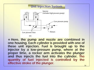
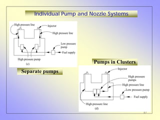
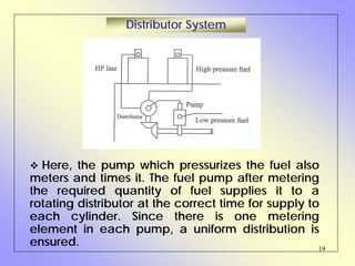
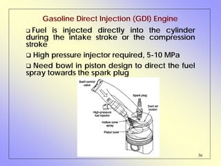
This document provides an overview of diesel engines, including their basic operation, components, and fuel injection systems. It describes how diesel engines ignite fuel via compression rather than a spark plug. Key points covered include the types of fuel injection systems (common rail, unit injection, etc.), injectors and nozzles, governors, and applications of diesel engines. The document concludes by comparing diesel engines to gasoline engines and discussing newer direct injection technologies.
this is the ppt on 2 stroke and 4 stroke petrol engine. . i made this ppt with the help of dhrumil patel .who is in the L.D. college of engineering in chemical department. . i am very thankful to him for being my great partner. . .thanx dhrumil..
The common rail fuel injection system is finding increasing use engines as it has the potential to drastically cut emissions and fuel consumption. This system provides control of many important parameters linked to the injection system. It has a wide range of applications, From small to heavy-duty engines.
This slides are about inline injection pump and calibration of the pumps .The working of the pump is described in simple words and with examples of daily usable devices.
This presentation include the information about the different types of superchargers, advantages & disadvantages of superchargers and turbochargers. One case study of variable geometry turbocharger is included with literature review.
ENGINE AUXILIARY SYSTEMS
Electronically controlled gasoline injection system for SI engines, Electronically controlled diesel injection system (Unit injector system, Rotary distributor type and common rail direct injection system), Electronic ignition system (Transistorized coil ignition system, capacitive discharge ignition system), Turbo chargers (WGT, VGT), Engine emission control by three way catalytic converter system, Emission norms (Euro and BS).
Electronically controlled gasoline injection system for SI engines – Electronically controlled diesel injection system – unit injector system, rotary distributor type and common rail direct injection system – Electronic ignition system: transistorized coil ignition system, capacitive discharge ignition system – Turbochargers - waste gate turbocharger, variable geometry turbocharger – engine emission control by three way catalytic converter system – emission norms (Euro, BS).
UNIT-II-ENGINE AUXILIARY SYSTEMS &TURBOCHARGERDineshKumar4165
Electronically controlled gasoline injection system for SI engines, Electronically controlled diesel injection system, Unit injector system, Rotary distributor type and common rail direct injection system, Electronic ignition system - Transistorized coil ignition system, capacitive discharge ignition system, Turbo chargers -Waste Gate Turbocharger, Variable Geomentry Turbocharger, Engine emission control by three way catalytic converter system, Emission norms (Euro and BS).
ICE_Handout(5) for CI fuel injection.pdf20007134009
FUEL INJECTION SYSTEM FOR CI ENGINES
The function of a fuel injection system is to meter the appropriate quantity of fuel for the given
engine speed and load to each cylinder, each cycle, and inject that fuel at the appropriate time in the
cycle at the desired rate with the spray configuration required for the particular combustion
chamber employed. It is important that injection begin and end cleanly, and avoid any secondary
injections. To accomplish this function, fuel is usually drawn from the fuel tank by a supply pump,
and forced through a filter to the injection pump. The injection pump sends fuel under pressure to
the nozzle pipes which carry fuel to the injector nozzles located in each cylinder head. Excess fuel
goes back to the fuel tank. CI engines are operated unthrottled, with engine speed and power
controlled by the amount of fuel injected during each cycle. This allows for high volumetric
efficiency at all speeds, with the intake system designed for very little flow restriction of the
incoming air.
FUNCTIONAL REQUIREMENTS OF AN INJECTION SYSTEM
For a proper running and good performance of the engine, the following requirements must be met
by the injection system:
• Accurate metering of the fuel injected per cycle. Metering errors may cause drastic variation
from the desired output. The quantity of the fuel metered should vary to meet changing speed
and load requirements of the engine.
• Correct timing of the injection of the fuel in the cycle so that maximum power is obtained.
• Proper control of rate of injection so that the desired heat-release pattern is achieved during
combustion.
• Proper atomization of fuel into very fine droplets.
• Proper spray pattern to ensure rapid mixing of fuel and air.
• Uniform distribution of fuel droplets throughout the combustion chamber
• To supply equal quantities of metered fuel to all cylinders in case of multi-cylinder engines.
• No lag during beginning and end of injection i.e., to eliminate dribbling of fuel droplets into the
cylinder.
TYPES OF INJECTION SYSTEMS
There are basically two types of injection systems: Air injection system and solid injection system.
Air Injection System: In this system, fuel is forced into the cylinder by means of compressed air.
This system is little used nowadays, because it requires a bulky multi-stage air compressor. This
causes an increase in engine weight and reduces the brake power output further. One advantage that
is claimed for the air injection system is good mixing of fuel with the air resulting in higher mean
effective pressure. Another advantage is its ability to utilize fuels of high viscosity which are less
expensive than those used by the engines with solid injection systems. These advantages are off-set
by the requirement of a multistage compressor thereby making the air-injection system obsolete.
Solid Injection System: In this system the liquid fuel is injected directly in.
Unit Injector System: In this syst
Electronic fuel injection vs carburettorsSalman Ahmed
These slides give you an idea of the different types of fuel injection systems that have been used throughout time.
A comparison between carburettors and EFI has been also looked on.
Hybrid optimization of pumped hydro system and solar- Engr. Abdul-Azeez.pdffxintegritypublishin
Advancements in technology unveil a myriad of electrical and electronic breakthroughs geared towards efficiently harnessing limited resources to meet human energy demands. The optimization of hybrid solar PV panels and pumped hydro energy supply systems plays a pivotal role in utilizing natural resources effectively. This initiative not only benefits humanity but also fosters environmental sustainability. The study investigated the design optimization of these hybrid systems, focusing on understanding solar radiation patterns, identifying geographical influences on solar radiation, formulating a mathematical model for system optimization, and determining the optimal configuration of PV panels and pumped hydro storage. Through a comparative analysis approach and eight weeks of data collection, the study addressed key research questions related to solar radiation patterns and optimal system design. The findings highlighted regions with heightened solar radiation levels, showcasing substantial potential for power generation and emphasizing the system's efficiency. Optimizing system design significantly boosted power generation, promoted renewable energy utilization, and enhanced energy storage capacity. The study underscored the benefits of optimizing hybrid solar PV panels and pumped hydro energy supply systems for sustainable energy usage. Optimizing the design of solar PV panels and pumped hydro energy supply systems as examined across diverse climatic conditions in a developing country, not only enhances power generation but also improves the integration of renewable energy sources and boosts energy storage capacities, particularly beneficial for less economically prosperous regions. Additionally, the study provides valuable insights for advancing energy research in economically viable areas. Recommendations included conducting site-specific assessments, utilizing advanced modeling tools, implementing regular maintenance protocols, and enhancing communication among system components.
Industrial Training at Shahjalal Fertilizer Company Limited (SFCL)MdTanvirMahtab2
This presentation is about the working procedure of Shahjalal Fertilizer Company Limited (SFCL). A Govt. owned Company of Bangladesh Chemical Industries Corporation under Ministry of Industries.
Water scarcity is the lack of fresh water resources to meet the standard water demand. There are two type of water scarcity. One is physical. The other is economic water scarcity.
Saudi Arabia stands as a titan in the global energy landscape, renowned for its abundant oil and gas resources. It's the largest exporter of petroleum and holds some of the world's most significant reserves. Let's delve into the top 10 oil and gas projects shaping Saudi Arabia's energy future in 2024.
Event Management System Vb Net Project Report.pdfKamal Acharya
In present era, the scopes of information technology growing with a very fast .We do not see any are untouched from this industry. The scope of information technology has become wider includes: Business and industry. Household Business, Communication, Education, Entertainment, Science, Medicine, Engineering, Distance Learning, Weather Forecasting. Carrier Searching and so on.
My project named “Event Management System” is software that store and maintained all events coordinated in college. It also helpful to print related reports. My project will help to record the events coordinated by faculties with their Name, Event subject, date & details in an efficient & effective ways.
In my system we have to make a system by which a user can record all events coordinated by a particular faculty. In our proposed system some more featured are added which differs it from the existing system such as security.
Cosmetic shop management system project report.pdfKamal Acharya
Buying new cosmetic products is difficult. It can even be scary for those who have sensitive skin and are prone to skin trouble. The information needed to alleviate this problem is on the back of each product, but it's thought to interpret those ingredient lists unless you have a background in chemistry.
Instead of buying and hoping for the best, we can use data science to help us predict which products may be good fits for us. It includes various function programs to do the above mentioned tasks.
Data file handling has been effectively used in the program.
The automated cosmetic shop management system should deal with the automation of general workflow and administration process of the shop. The main processes of the system focus on customer's request where the system is able to search the most appropriate products and deliver it to the customers. It should help the employees to quickly identify the list of cosmetic product that have reached the minimum quantity and also keep a track of expired date for each cosmetic product. It should help the employees to find the rack number in which the product is placed.It is also Faster and more efficient way.
Welcome to WIPAC Monthly the magazine brought to you by the LinkedIn Group Water Industry Process Automation & Control.
In this month's edition, along with this month's industry news to celebrate the 13 years since the group was created we have articles including
A case study of the used of Advanced Process Control at the Wastewater Treatment works at Lleida in Spain
A look back on an article on smart wastewater networks in order to see how the industry has measured up in the interim around the adoption of Digital Transformation in the Water Industry.
Sachpazis:Terzaghi Bearing Capacity Estimation in simple terms with Calculati...Dr.Costas Sachpazis
Terzaghi's soil bearing capacity theory, developed by Karl Terzaghi, is a fundamental principle in geotechnical engineering used to determine the bearing capacity of shallow foundations. This theory provides a method to calculate the ultimate bearing capacity of soil, which is the maximum load per unit area that the soil can support without undergoing shear failure. The Calculation HTML Code included.
Automobile Management System Project Report.pdfKamal Acharya
The proposed project is developed to manage the automobile in the automobile dealer company. The main module in this project is login, automobile management, customer management, sales, complaints and reports. The first module is the login. The automobile showroom owner should login to the project for usage. The username and password are verified and if it is correct, next form opens. If the username and password are not correct, it shows the error message.
When a customer search for a automobile, if the automobile is available, they will be taken to a page that shows the details of the automobile including automobile name, automobile ID, quantity, price etc. “Automobile Management System” is useful for maintaining automobiles, customers effectively and hence helps for establishing good relation between customer and automobile organization. It contains various customized modules for effectively maintaining automobiles and stock information accurately and safely.
When the automobile is sold to the customer, stock will be reduced automatically. When a new purchase is made, stock will be increased automatically. While selecting automobiles for sale, the proposed software will automatically check for total number of available stock of that particular item, if the total stock of that particular item is less than 5, software will notify the user to purchase the particular item.
Also when the user tries to sale items which are not in stock, the system will prompt the user that the stock is not enough. Customers of this system can search for a automobile; can purchase a automobile easily by selecting fast. On the other hand the stock of automobiles can be maintained perfectly by the automobile shop manager overcoming the drawbacks of existing system.
2. 2
Diesel Engines - Facts
The diesel engine is a type of internal
combustion engine (more specifically, a
compression ignition engine) in which the fuel is
ignited by being suddenly exposed to the high
temperature and pressure of a compressed gas
containing oxygen (usually atmospheric air),
rather than a separate source of ignition energy
(such as a spark plug), as is the case in the
petrol engine.
This is known as the diesel cycle, after
German engineer Rudolf Diesel, who invented
it in 1892 and received the patent on February
23, 1893.
3. 3
• Initial CI engines were large
and slow.
• Heavy distillate petroleum was
forced into the cylinder using
compressed air.
• Robert Bosch began producing
injection systems in 1927.
Diesel Engines - Facts
4. 4
CI vs. SI EnginesCI vs. SI Engines
• SI engines draw fuel and air into the
cylinder.
• Fuel must be injected into the cylinder at
the desired time of combustion in CI
engines.
• Air intake is throttled to the SI engine -- no
throttling in CI engines.
• Compression ratios must be high enough to
cause auto-ignition in CI engines.
• Upper compression ratio in SI engines is
limited by the auto-ignition temperature.
• Flame front in SI engines smooth and
controlled.
• CI combustion is rapid and uncontrolled at
the beginning.
5. 5
Diesel Engines - Facts
In very cold weather, diesel fuel
thickens and increases in viscosity and
forms wax crystals or a gel. This can
make it difficult for the fuel injector to
get fuel into the cylinder in an effective
manner, making cold weather starts
difficult at times, though recent
advances in diesel fuel technology
have made these difficulties rare.
6. 6
Diesel Engines - Facts
A common method to electrically
heat the fuel filter and fuel lines. Other
engines utilize small electric heaters
called glow plugs inside the cylinder
to warm the cylinders prior to starting.
A small number use resistive grid
heaters in the intake manifold to warm
the inlet air until the engine reaches
operating temperature.
7. 7
Diesel Engines - Facts
A vital component of any diesel engine
system is the governor, which limits the speed
of the engine by controlling the rate of fuel
delivery.
Older governors were driven by a gear
system from the engine (and thus supplied
fuel only linearly with engine speed.)
Modern electronically-controlled engines
achieve this through the electronic control
module (ECM) or electronic control unit (ECU).
8. 8
Diesel Engines - Facts
The addition of a turbocharger or
supercharger (boost pressures can be
higher on diesels) to the engine greatly
assists in increasing fuel economy and
power output.
The higher compression ratio allows a
diesel engine to be more efficient than a
comparable spark ignition engine, although
the calorific value of the fuel is slightly lower
at 45.3 MJ/kg to gasoline at 45.8 MJ/kg.
9. 9
Diesel Engines - Applications
High-Speed (approximately 1200 rpm and
greater) engines are used to power lorries
(trucks), buses, tractors, cars, yachts,
compressors, pumps and small generators.
Large electrical generators are driven by
medium speed engines, (approx. 300 to 1200
rpm) optimized to run at a set speed and
provide a rapid response to load changes.
The largest diesel engines are used to power
ships. These engines have power outputs over
80,000 kW, turn at about 60 to 100 rpm, and are
up to 15 m tall. They often run on cheap low-
grade fuel, which require extra heat treatment
in the ship for tanking and before injection due
to their low volatility.
10. 10
Fuel Injection System -Requirements
The injected fuel must be broken into very fine
droplets
The fuel injection should occur at the correct
moment
It should supply the fuel in correct quantity as
required by the varying engine loads
The spray pattern should ensure rapid mixing
of fuel and air
It should supply equal quantities of metered
fuel to all the cylinders in a multi cylinder engines
The beginning and the end of injection should
be sharp
11. 11
Elements of Fuel Injection System
Distribution elements: to divide the metered
fuel equally among the cylinders
Pumping elements: to supply fuel from fuel
tank to cylinder
Metering elements: to meter fuel supply as
per load and speed
Timing controls: to adjust the start and the stop
of injection
Mixing elements: to atomize and distribute the
fuel within the combustion chamber
12. 12
Types of Injection Systems
Air (Blast) Injection System: In air blast
injection system, fuel is forced into the cylinder
by means of compressed air.
This method is capable of producing better
atomization and penetration of fuel resulting in
higher brake mean effective pressure.
This system is little used universally at present,
because it requires a multistage air
compressor, which increases engine weight
and reduces brake power.
13. 13
Types of Injection Systems – Contd.
Solid Injection System: In solid injection, the
liquid fuel is injected directly into the
combustion chamber without the aid of
compressed air. Hence, it is termed as airless
mechanical injection or solid injection.
Every solid injection system must have
a pressuring unit (the pump)
and
an atomizing unit (the injector).
14. 14
Solid Injection - Classification
Depending upon the location of the pumps
and injectors, and the manner of their
operations, solid injection systems may be
further classified as follows:
Common Rail System
Unit Injection System
Individual Pump and Nozzle System
Distributor System
15. 15
In this system, a high-pressure pump supplies
fuel to a fuel header as shown. The high-pressure
in the header forces the fuel to each of the nozzles
located in the cylinders. At the proper time, a
mechanically operated (by means of push rod
and rocker arm) valve allows the fuel to enter the
cylinder through nozzle.
Common Rail System
Injector
High pressure pump
Fuel supply
High presure line
Header
(a)
16. 16
Here, the pump and nozzle are combined in
one housing. Each cylinder is provided with one of
these unit injectors. Fuel is brought up to the
injector by a low-pressure pump, where at the
proper time, a rocker arm activates the plunger
and thus injects the fuel into the cylinder. The
quantity of fuel injected is controlled by the
effective stroke of the plunger.
Unit Injection System
Injector
(includes high pressure pump)
Low pressure pump
ReturnLow pressure lines
(b)
17. 17
Individual Pump and Nozzle Systems
Injector
High pressure line
Low pressure
pump
Fuel supply
High pressure pump
High pressure line
(c)
Injector
High pressure
pumps
High pressure line
Low pressure pump
Fuel supply
High pressure line
(d)
Separate pumps
Pumps in Clusters
18. 18
Individual Pump & Nozzle Systems – contd.
In this system, each cylinder is provided with
one pump and one injector. This type differs
from the unit injector in that the pump and
injector are separated from each other, i.e., the
injector is located on the cylinder, while the
pump is placed on the side of the engine. Each
pump may be placed close to the cylinder, or
may be arranged in a cluster. The high-pressure
pump plunger is actuated by a cam, and
produces the fuel pressure necessary to open
the injector valve at the correct time. The
quantity of fuel injected is again controlled by
the effective stroke of the plunger.
19. 19
Here, the pump which pressurizes the fuel also
meters and times it. The fuel pump after metering
the required quantity of fuel supplies it to a
rotating distributor at the correct time for supply to
each cylinder. Since there is one metering
element in each pump, a uniform distribution is
ensured.
Distributor System
20. 20
Injection Pump and Governor
The main objective of the fuel injection pump
is to deliver accurately a metered quantity of
fuel under high pressure at the correct instant to
the injector fitted on each cylinder. Two types of
pumps are generally used viz., jerk type and
distributor type.
Fuel delivered by a pump increases with
speed while the opposite is true about the air
intake. This results in over fueling at higher
speeds. At low speeds, the engine tends to stall
due to insufficiency of fuel. To overcome this,
injector pump governors are generally used.
Two types of governors are found in applications
viz., (a) mechanical governor and (b)
pneumatic governor.
21. 21
Fuel Injectors and Nozzles
Quick and complete combustion is ensured by
a well designed fuel injector. By atomizing the
fuel into very fine droplets, it increases the
surface area of the droplets resulting in better
mixing and subsequent combustion. Atomization
is done by forcing the fuel through a small orifice
under high pressure. An injector assembly
consists of the following components.
a needle valve
a compression spring
a nozzle
an injector body
24. 24
Operation
Fuel is injected by a pump. The pump exerts
sufficient pressure/force that lifts the nozzle
valve.
The spring tension and hence the valve
operating pressure is controlled by adjusting the
screw at the top.
When the nozzle valve is lifted up, fuel is
sprayed into the combustion chamber. As the
fuel supply is exhausted, the spring pushes the
valve back on its seat.
25. 25
Nozzle
The nozzle sprays the liquid fuel. The functions
of the nozzle are: (a) atomization, (b)
distribution of fuel to the required area, (c) non-
impingement on the walls, and (d) no dribbling.
Note: The fuel striking on the walls decomposes
and produces carbon deposits. This causes
smoky exhaust and increases fuel consumption.
Note: High injection pressure allows better
dispersion and penetration into the combustion
chamber. High air density in the cylinder gives
high resistance to the droplets. This further
causes dispersion.
28. 28
The single hole nozzle requires a
high injection pressure and this type
of nozzle has a tendency to dribble.
The spray cone angle is usually
narrow, and this gives poor mixing
unless the velocity is high.
The pintle nozzle has been
developed to avoid weak injection
and dribbling. The spindle is
provided with a pintle capable of
protruding in and out. Pintle nozzle
results in good atomization and
reduced penetration.
Types of Nozzles
(a) Single hole
(b) Pintle nozzle
30. 30
A multihole nozzle, where the
number of holes may vary from 4
to 18, allows a proper mixing of air
and fuel. The advantage lies with
the ability to distribute the fuel
properly even with lower air
motion within the chamber.
Types of Nozzles
The pintaux nozzle is a pintle
nozzle with an auxiliary hole drilled
into the nozzle body. At low
speeds, the needle valve does not
lift fully and most of the fuel is
injected through this auxiliary hole.
Hole angle
(c) Multiple hole
(d) Pintaux nozzle
Auxiliary hole
31. 31
Vf = the fuel jet velocity at the orifice exit
arg
inj
cyl
d
where p injection pressure
p cylinder pressure
density of fuelf
C coefficient of disch e for orifice
ρ
=
=
=
=
2
inj cyl
f d
f
p p
V C
ρ
⎛ ⎞−
∴ = ⎜ ⎟
⎜ ⎟
⎝ ⎠
32. 32
Volume of flow injected per second, Q
2 60
4 360 60
i
f
N
Q d n V
N
π θ
∴ =
Area of all orifices Time of one injection
No. of injection per
sec for one orifice
d = diameter of orifice
n = no. of orifices
θ = duration of injection in crank angle degrees
N = rpm/2 for four stroke
= rpm for two stroke
Ni = no. of injection per minute
33. 33
Diesel Engines - Facts
Diesel engines are rather unpopular in the
United States, often being thought of as loud
and dirty. Worldwide, however, diesel engines
are very well established in a wide variety of
applications, as they are much more efficient
than gasoline engines and generally longer
lasting.
35. 35
Diesel Fuel Injection System
With diesel engines fuel is
sprayed directly into the
cylinders power is varied by
metering the amount of fuel
added (no throttle). Diesel fuel
injection systems operate at
high-pressure, e.g., 100 Mpa.
In this system, fuel pressure
must be greater than the
compression pressure, and the
system needs high fuel jet
speed to atomize droplets
small enough for rapid
evaporation.
Traditional Diesels high pressure produced locally within the injector
Latest Diesels use high pressure common rail with solenoid actuated
injectors
36. 36
Gasoline Direct Injection (GDI) Engine
Fuel is injected directly into the cylinder
during the intake stroke or the compression
stroke
High pressure injector required, 5-10 MPa
Need bowl in piston design to direct the fuel
spray towards the spark plug
37. 37
Engine that combines the best features of SI
and CI engines:
• Operate at optimum compression ratio (12-
15) for efficiency by injecting fuel directly into
engine during compression (avoiding knock
associated with SI engines with premixed
charge)
• Ignite the fuel as it mixes (avoid fuel-quality
requirement of diesel fuel)
• Control engine power by fuel added (no
throttling no pumping work)
• During intake stroke fuel cools the cylinder
wall allowing more air into the cylinder due to
higher density
Benefits of GDI Engine
38. 38
Direct-Injection Stratified-Charge Engines
• Create easily ignitable fuel-air mixture at the
spark plug and a leaner fuel-air mixture in the
rest of the cylinder.
• Lean burn results in lower emissions and higher
energy efficiency
Example:
Mitsubishi GDI engine achieves complete
combustion with an air-fuel ratio of 40:1
compared to 15:1 for conventional engines
This results in a 20% improvement in overall fuel
efficiency and CO2 production, and reduces
NOx emissions by 95% with special catalyst
39. 39
1.1. Crouse WH,Crouse WH, andand Anglin DLAnglin DL, (1985), Automotive Engines, Tata McGraw Hill.
2.2. Eastop TD,Eastop TD, andand McConkey A,McConkey A, (1993), Applied Thermodynamics for Engg.
Technologists, Addison Wisley.
3.3. Fergusan CR,Fergusan CR, andand Kirkpatrick ATKirkpatrick AT,, (2001), Internal Combustion Engines, John
Wiley & Sons.
4.4. Ganesan VGanesan V,, (2003), Internal Combustion Engines, Tata McGraw Hill.
5.5. Gill PW, Smith JH,Gill PW, Smith JH, andand Ziurys EJZiurys EJ,, (1959), Fundamentals of I. C. Engines, Oxford
and IBH Pub Ltd.
6.6. Heisler H,Heisler H, (1999), Vehicle and Engine Technology, Arnold Publishers.
7.7. Heywood JB,Heywood JB, (1989), Internal Combustion Engine Fundamentals, McGraw Hill.
8.8. Heywood JB,Heywood JB, andand Sher E,Sher E, (1999), The Two-Stroke Cycle Engine, Taylor & Francis.
9.9. Joel R,Joel R, (1996),(1996), Basic Engineering Thermodynamics, Addison-Wesley.
10.10. Mathur ML, and Sharma RP,Mathur ML, and Sharma RP, (1994), A Course in Internal Combustion Engines,
Dhanpat Rai & Sons, New Delhi.
11.11. Pulkrabek WW,Pulkrabek WW, (1997), Engineering Fundamentals of the I. C. Engine, Prentice Hall.
12.12. Rogers GFC,Rogers GFC, andand Mayhew YRMayhew YR, (1992), Engineering Thermodynamics, Addison
Wisley.
13.13. Srinivasan S,Srinivasan S, (2001), Automotive Engines, Tata McGraw Hill.
14.14. Stone R,Stone R, (1992), Internal Combustion Engines, The Macmillan Press Limited, London.
15.15. Taylor CF,Taylor CF, (1985), The Internal-Combustion Engine in Theory and Practice, Vol.1 & 2,
The MIT Press, Cambridge, Massachusetts.
References