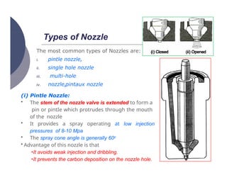
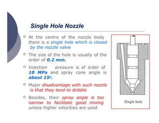
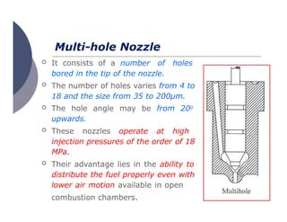
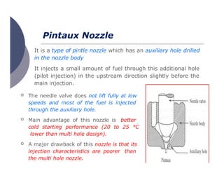
Fuel Injection System
Introduction
 The Functions of Fuel Injection
System
 To enhance the engine
 performance
 Fuel economy
 initiating and controlling the combustion
process
 preparation of the combustible charge (Just
like carburetor)
The main difference between Carburetor and Fuel injection
system
 Carburetor
 Fuel is atomized by processes relying on the air speed
greater than fuel speed at the fuel nozzle,
 The amount of fuel drawn into the engine depends upon
the air velocity in the venturi
 Fuel Injection System
 The fuel speed at the point of delivery is greater than the
air speed to atomize the fuel.
 the amount of fuel delivered into the air stream going to
the engine is controlled by a pump which forces the
fuel under pressure
Functional Requirements of An Injection System
i. Accurate metering of the fuel injected per cycle: The
quantity of the fuel metered should vary to met changing
speed and load requirements of the engine
ii. Timing the injection of the fuel correctly in the
cycle:
iii.
to obtain maximum power ensuring fuel economy and
clean burning
Proper control of rate of injection: The desired
heat-
release pattern is achieved during combustion
iv. Proper atomization of fuel into very fine droplets.
v. Proper spray pattern to ensure rapid mixing of fuel
and air
vi. Uniform distribution of fuel droplets throughout the
combustion chamber
vii. To supply equal quantities of
metered fuel to all cylinders case of
multi cylinder engines
viii.No lag during beginning and end of
injection i.e., to eliminate dribbling of fuel
droplets into the cylinder
Classification of Injection Systems
 A fuel-injection system is required to inject and
atomize fuel in to the cylinder of CI engines.
 For producing the required pressure for atomizing
the fuel either air or a mechanical means is used.
 Thus the injection systems can be classified as:
 Air injection system
 Solid injection systems
Air Injection System
cylinder by means of
 Fuel is forced into
the
compressed air
 It has good mixing of fuel with the
air with resultant higher mean effective
pressure
 It has the ability to utilize high
viscosity (less expensive) fuels
 The system is obsolete due to the requirement
of multistage air compressors.
Solid Injection System
 In this system the liquid fuel is injected directly
into the combustion chamber without the aid of
compressed air.
 Solid injection systems can be classified into four
types.
 Individual pump and nozzle system
 Unit injector system
 Common rail system
 Distributor system
INJECTION PUMP
 The main objectives of fuel-injection pump is to
deliver accurately metered quantity of fuel under
high pressure (in the range from 120 to 200 bar)
at the correct instant to the injector fitted on each
cylinder.
 Injection pumps are generally of two types,
 Jerk type pumps
 Distributor type pumps
Fig: Single Cylinder Jerk Pump Type Fuel-Injection System
Jerk Type Pumps
Jerk Type Pumps
 the axial movement of the plunger is through cam
shaft, its rotational movement about its axis by
means of rack D.
 the fuel gets filled in the barrel, When the plunger is
below port A
 the port A is closed, As the plunger rises
 the fuel will flow out through port C
 Port C is closed, when rack rotates the plunger
 the fuel is past the check valve through orifice B to the
injector due to the high pressure developed
 The injection continues till the helical indentation on
the plunger uncovers port C
Pump filling & Pumping Cycle
 Open-Barrel
Filling
Cut-off-
of
 Port
beginning
injection
 Port spills end
of injection
Fuel Delivery Output Control
 the axial distance traversed by the plunger is same for
every stroke
 The point on the upward travel of the plunger at
which the spill occurs can be altered by twisting the
plunger relative to the barrel
 This enables the position of the plunger helical spill
groove to be varied relative to the fixed barrel spill
port, it there by increase or decreases the effective
pumping stroke the plunger.
Fuel Delivery Output Control
 To reduce delivery (b): The
helical groove must be made to
align with the spill port earlier in
the plunger up stroke by
rotating the plunger θh degree
 To increase Delivery (c): The
helix groove must be aligned
with the spill port later in the
plunger stroke by rotating the
plunger θf degrees so that the
effective plunger stroke will be
lengthened before spill occur
oNo delivery (shut-off Position) (a): by rotating it until the
helical groove uncovers the spill Port in the barrel for entire
strike
Distributor Type Pump (DPA Type)
 This pump has only a single pumping element and the
fuel is distributed to each cylinder by means of a rotor
A central longitudinal passage in the
rotor and also two sets of radial
holes (each equal to the number of
engine cylinders) located at
different heights.
One set is connected to pump inlet
via central passage whereas the
second set is connected to delivery
lines leading to injectors of the
various cylinders.
 The fuel is drawn into the central
rotor passage from the inlet port
when the pump plunger move
away from each other.
 Wherever, the
passage in
the
radial
rotor
delivery
coincides
with the delivery port for any
cylinder the fuel is delivered to
each cylinder in turn.
 Main advantages of this type of
pump lies in its small size and
its light weight
Governor
 In a CI Engine the fuel delivered is independent of the
injection pump characteristic and the air intake
 Fuel delivered by a pump increases with speed whereas
the opposite is true about the air intake
 This results in
 over fueling at higher speeds.
 the engine tends to stall at idling speeds (low speeds)
due to insufficiency of fuel.
 Quantity of fuel delivered increases with load
causing
excessive carbon deposits and high exhaust temperature
 Drastic reduction in load will cause over speeding
to dangerous values
Mechanical Governor
 Governors are generally of two types,
 Mechanical governor
 Pneumatic governor
When the engine speed tends
to exceed the limit the weights
fly apart. This causes the bell
crank levers to raise the sleeve
and operate the control
lever in downward direction.
This actuates the control
rack
Pneumatic Governor
 The amount of
vacuum applied to the
diaphragm is
controlled
accelerator
by the
pedal through
the position of the butterfly
valve in the venturi unit
 A diaphragm is connected
to the fuel pump control
rack
 position of the accelerator
pedal also determines the
position of the pump
control rack and hence the
amount of fuel injected.
Fuel Injector
 Fuel injectors atomize the fuel into very fine droplets,
and increases the surface area of the fuel droplets
resulting in better mixing and
subsequent combustion
 Atomization is done by forcing the fuel
through a small orifice under high pressure.
 The injector assembly consists of
 a needle valve
 a compression spring
 a nozzle
 an injector body
by the injection
 Fuel supplied
pump exerts sufficient
force
against the spring to lift
the nozzle valve
 After
injection
pressure
pushes
the spring
the
nozzle
valve back on its seat
 small quantity of fuel is allowed
to leak through the clearance
between nozzle valve and its
guide for proper lubrication
 valve
opening
controlled by
pressure
is
adjusting
the
screw (spring tension)
NOZZLE
 Nozzle is that part of an injector through which the liquid fuel
is sprayed into the combustion chamber.
 The nozzle should fulfill the following functions.
i. Atomization: This is a very important function since it is the
first phase in obtaining proper mixing of the fuel and air in the
combustion chamber.
ii. Distribution of fuel: Distribution of fuel to the required
areas within the combustion chamber. Factors affecting this
are:
 Injection pressure:
 Density of air in the cylinder:
 Physical properties of fuel: The properties like self-
ignition temperature, vapor pressure, viscosity, etc.
iii.Prevention of impingement on walls:
Prevention of the fuel from impinging directly on
the walls of combustion chamber or piston. This is
necessary because fuel striking the walls,
decomposes and produces carbon deposits.
This causes smoky exhaust as well as increase in
fuel consumption.
iv.Mixing: Mixing the fuel and air in case of non-
turbulent type of combustion chamber should
be taken care of by the nozzle.
Types of Nozzle
The most common types of Nozzles are:
iii.
i. pintle nozzle,
ii. single hole nozzle
multi-hole
nozzle,
iv. pintaux nozzle
(i) Pintle Nozzle:
• The stem of the nozzle valve is extended to form a
pin or pintIe which protrudes through the mouth
of the nozzle
• It provides a spray operating at low injection
pressures of 8-10 Mpa
• The spray cone angle is generally 600
• Advantage of this nozzle is that
•It avoids weak injection and dribbling.
•It prevents the carbon deposition on the nozzle hole.
 At the centre of the nozzle body
there is a single hole which is closed
by the nozzle valve
Single Hole Nozzle
 The size of the hole is usually of the
order of 0.2 mm.
 Injection pressure is of order of
8-
10 MPa and spray cone angle is
about 150.
 Major disadvantage with such nozzle
is that they tend to dribble
 Besides, their spray angle is too
narrow to facilitate good mixing
unless higher velocities are used
Multi-hole Nozzle
 It consists of a number of holes
bored in the tip of the nozzle.
 The number of holes varies from 4 to
18 and the size from 35 to 200μm.
 The hole angle may be from 200
upwards.
 These nozzles operate at high
injection pressures of the order of 18
MPa.
 Their advantage lies in the ability to
distribute the fuel properly even with
lower air motion available in open
combustion chambers.
Pintaux Nozzle
It is a type of pintle nozzle which has an auxiliary hole drilled
in the nozzle body
It injects a small amount of fuel through this additional hole
(pilot injection) in the upstream direction slightly before the
main injection.
 The needle valve does not lift fully at low
speeds and most of the fuel is injected
through the auxiliary hole.
 Main advantage of this nozzle is better
cold starting performance (20 to 25 °C
lower than multi hole design).
 A major drawback of this nozzle is that its
injection characteristics are poorer than
the multi hole nozzle.

Fuel Injection System and Injector & Its Types.pptx

  • 1.
  • 2.
    Introduction  The Functionsof Fuel Injection System  To enhance the engine  performance  Fuel economy  initiating and controlling the combustion process  preparation of the combustible charge (Just like carburetor)
  • 3.
    The main differencebetween Carburetor and Fuel injection system  Carburetor  Fuel is atomized by processes relying on the air speed greater than fuel speed at the fuel nozzle,  The amount of fuel drawn into the engine depends upon the air velocity in the venturi  Fuel Injection System  The fuel speed at the point of delivery is greater than the air speed to atomize the fuel.  the amount of fuel delivered into the air stream going to the engine is controlled by a pump which forces the fuel under pressure
  • 4.
    Functional Requirements ofAn Injection System i. Accurate metering of the fuel injected per cycle: The quantity of the fuel metered should vary to met changing speed and load requirements of the engine ii. Timing the injection of the fuel correctly in the cycle: iii. to obtain maximum power ensuring fuel economy and clean burning Proper control of rate of injection: The desired heat- release pattern is achieved during combustion iv. Proper atomization of fuel into very fine droplets. v. Proper spray pattern to ensure rapid mixing of fuel and air vi. Uniform distribution of fuel droplets throughout the combustion chamber
  • 5.
    vii. To supplyequal quantities of metered fuel to all cylinders case of multi cylinder engines viii.No lag during beginning and end of injection i.e., to eliminate dribbling of fuel droplets into the cylinder
  • 6.
    Classification of InjectionSystems  A fuel-injection system is required to inject and atomize fuel in to the cylinder of CI engines.  For producing the required pressure for atomizing the fuel either air or a mechanical means is used.  Thus the injection systems can be classified as:  Air injection system  Solid injection systems
  • 7.
    Air Injection System cylinderby means of  Fuel is forced into the compressed air  It has good mixing of fuel with the air with resultant higher mean effective pressure  It has the ability to utilize high viscosity (less expensive) fuels  The system is obsolete due to the requirement of multistage air compressors.
  • 8.
    Solid Injection System In this system the liquid fuel is injected directly into the combustion chamber without the aid of compressed air.  Solid injection systems can be classified into four types.  Individual pump and nozzle system  Unit injector system  Common rail system  Distributor system
  • 9.
    INJECTION PUMP  Themain objectives of fuel-injection pump is to deliver accurately metered quantity of fuel under high pressure (in the range from 120 to 200 bar) at the correct instant to the injector fitted on each cylinder.  Injection pumps are generally of two types,  Jerk type pumps  Distributor type pumps
  • 10.
    Fig: Single CylinderJerk Pump Type Fuel-Injection System
  • 11.
  • 12.
    Jerk Type Pumps the axial movement of the plunger is through cam shaft, its rotational movement about its axis by means of rack D.  the fuel gets filled in the barrel, When the plunger is below port A  the port A is closed, As the plunger rises  the fuel will flow out through port C  Port C is closed, when rack rotates the plunger  the fuel is past the check valve through orifice B to the injector due to the high pressure developed  The injection continues till the helical indentation on the plunger uncovers port C
  • 13.
    Pump filling &Pumping Cycle  Open-Barrel Filling Cut-off- of  Port beginning injection  Port spills end of injection
  • 14.
    Fuel Delivery OutputControl  the axial distance traversed by the plunger is same for every stroke  The point on the upward travel of the plunger at which the spill occurs can be altered by twisting the plunger relative to the barrel  This enables the position of the plunger helical spill groove to be varied relative to the fixed barrel spill port, it there by increase or decreases the effective pumping stroke the plunger.
  • 15.
    Fuel Delivery OutputControl  To reduce delivery (b): The helical groove must be made to align with the spill port earlier in the plunger up stroke by rotating the plunger θh degree  To increase Delivery (c): The helix groove must be aligned with the spill port later in the plunger stroke by rotating the plunger θf degrees so that the effective plunger stroke will be lengthened before spill occur oNo delivery (shut-off Position) (a): by rotating it until the helical groove uncovers the spill Port in the barrel for entire strike
  • 16.
    Distributor Type Pump(DPA Type)  This pump has only a single pumping element and the fuel is distributed to each cylinder by means of a rotor A central longitudinal passage in the rotor and also two sets of radial holes (each equal to the number of engine cylinders) located at different heights. One set is connected to pump inlet via central passage whereas the second set is connected to delivery lines leading to injectors of the various cylinders.
  • 17.
     The fuelis drawn into the central rotor passage from the inlet port when the pump plunger move away from each other.  Wherever, the passage in the radial rotor delivery coincides with the delivery port for any cylinder the fuel is delivered to each cylinder in turn.  Main advantages of this type of pump lies in its small size and its light weight
  • 18.
    Governor  In aCI Engine the fuel delivered is independent of the injection pump characteristic and the air intake  Fuel delivered by a pump increases with speed whereas the opposite is true about the air intake  This results in  over fueling at higher speeds.  the engine tends to stall at idling speeds (low speeds) due to insufficiency of fuel.  Quantity of fuel delivered increases with load causing excessive carbon deposits and high exhaust temperature  Drastic reduction in load will cause over speeding to dangerous values
  • 19.
    Mechanical Governor  Governorsare generally of two types,  Mechanical governor  Pneumatic governor When the engine speed tends to exceed the limit the weights fly apart. This causes the bell crank levers to raise the sleeve and operate the control lever in downward direction. This actuates the control rack
  • 20.
    Pneumatic Governor  Theamount of vacuum applied to the diaphragm is controlled accelerator by the pedal through the position of the butterfly valve in the venturi unit  A diaphragm is connected to the fuel pump control rack  position of the accelerator pedal also determines the position of the pump control rack and hence the amount of fuel injected.
  • 21.
    Fuel Injector  Fuelinjectors atomize the fuel into very fine droplets, and increases the surface area of the fuel droplets resulting in better mixing and subsequent combustion  Atomization is done by forcing the fuel through a small orifice under high pressure.  The injector assembly consists of  a needle valve  a compression spring  a nozzle  an injector body
  • 22.
    by the injection Fuel supplied pump exerts sufficient force against the spring to lift the nozzle valve  After injection pressure pushes the spring the nozzle valve back on its seat  small quantity of fuel is allowed to leak through the clearance between nozzle valve and its guide for proper lubrication  valve opening controlled by pressure is adjusting the screw (spring tension)
  • 23.
    NOZZLE  Nozzle isthat part of an injector through which the liquid fuel is sprayed into the combustion chamber.  The nozzle should fulfill the following functions. i. Atomization: This is a very important function since it is the first phase in obtaining proper mixing of the fuel and air in the combustion chamber. ii. Distribution of fuel: Distribution of fuel to the required areas within the combustion chamber. Factors affecting this are:  Injection pressure:  Density of air in the cylinder:  Physical properties of fuel: The properties like self- ignition temperature, vapor pressure, viscosity, etc.
  • 24.
    iii.Prevention of impingementon walls: Prevention of the fuel from impinging directly on the walls of combustion chamber or piston. This is necessary because fuel striking the walls, decomposes and produces carbon deposits. This causes smoky exhaust as well as increase in fuel consumption. iv.Mixing: Mixing the fuel and air in case of non- turbulent type of combustion chamber should be taken care of by the nozzle.
  • 25.
    Types of Nozzle Themost common types of Nozzles are: iii. i. pintle nozzle, ii. single hole nozzle multi-hole nozzle, iv. pintaux nozzle (i) Pintle Nozzle: • The stem of the nozzle valve is extended to form a pin or pintIe which protrudes through the mouth of the nozzle • It provides a spray operating at low injection pressures of 8-10 Mpa • The spray cone angle is generally 600 • Advantage of this nozzle is that •It avoids weak injection and dribbling. •It prevents the carbon deposition on the nozzle hole.
  • 26.
     At thecentre of the nozzle body there is a single hole which is closed by the nozzle valve Single Hole Nozzle  The size of the hole is usually of the order of 0.2 mm.  Injection pressure is of order of 8- 10 MPa and spray cone angle is about 150.  Major disadvantage with such nozzle is that they tend to dribble  Besides, their spray angle is too narrow to facilitate good mixing unless higher velocities are used
  • 27.
    Multi-hole Nozzle  Itconsists of a number of holes bored in the tip of the nozzle.  The number of holes varies from 4 to 18 and the size from 35 to 200μm.  The hole angle may be from 200 upwards.  These nozzles operate at high injection pressures of the order of 18 MPa.  Their advantage lies in the ability to distribute the fuel properly even with lower air motion available in open combustion chambers.
  • 28.
    Pintaux Nozzle It isa type of pintle nozzle which has an auxiliary hole drilled in the nozzle body It injects a small amount of fuel through this additional hole (pilot injection) in the upstream direction slightly before the main injection.  The needle valve does not lift fully at low speeds and most of the fuel is injected through the auxiliary hole.  Main advantage of this nozzle is better cold starting performance (20 to 25 °C lower than multi hole design).  A major drawback of this nozzle is that its injection characteristics are poorer than the multi hole nozzle.