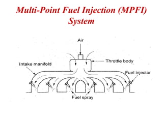
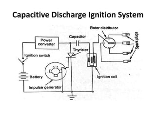
SlideShare a Scribd company logo
1 of 81
KONGUNADU COLLEGE OF ENGINEERING AND TECHNOLOGY
(AUTONOMOUS)
NAMAKKAL- TRICHY MAIN ROAD, THOTTIAM, TRICHY
DEPARTMENT OF MECHANICAL ENGINEERING
20ME603PE - AUTOMOBILE ENGINEERING
SIXTH SEMESTER
PRESENTED BY
M.DINESHKUMAR,
ASSISTANT PROFESSOR,
DEPARTMENT OF MECHANICAL ENGINEERING,
KONGUNADU COLLEGE OF ENGINEERING AND TECHNOLOGY.
ENGINE AUXILIARY SYSTEMS
UNIT-II
CARBURETORS:
• Carburetor is a device used for atomoizing and vapourizing the
fuel and mixing it with the air in varying proportions to suit for
changing the operating conditions of engines.
Functions of carburetor:
 It prepares a mixture of petrol and air in correct proportions.
 It maintains a small reserve of petrol in the float chamber at
constant head
 It atomizes and vaporizes the fuel.
 It supplies a fine spray of petrol
 It produces a homogeneous mixture
 It measures and supplies the proper quantity and proportions of
air and fuel under all conditions of engine operation such as
temperature, speed and load
INJECTIONSYSTEM
In SI engines, fuel-injection pumps are often used
instead of conventional carburetors.
The primary difference between carburetors and
fuel injection is that fuel injection atomizes the
fuel through a small nozzle under high pressure,
while a carburetor relies on suction created by
intake air accelerated through a venturi tube to
draw the fuel into the airstream.
Fuel injection into the cylinders distributes the
fuel more evenly to the individual cylinders than
the carburetor system.
Therefore, more power can be developed and
undesirable emissions are reduced.
Requirements of fuel injection system
The beginning as well as end of injection
should sharply take place
The fuel is injected at correct time in the cycle
throughout the speed range of the engine
The injection of fuel should occur at the
correct rate and in the correct quantity a
required by varying the engine food.
The fuel is atomized to the required degree.
The fuel is distributed throughout the
combustion chamber for better mixing
INJECTION SYSTEM FOR SI ENGINE
In a petrol injection system, the fuel is injected
into the intake manifold through fuel injection
valves. There are two basic gasoline injection
arrangements.
(i) Multi-point injection system
(ii) Monopoint injection system.
Multi-Point Fuel Injection (MPFI)
System
Multi-Point Fuel Injection (MPFI)
System
• It is also called port injection system.
• In this system, there is an injection valve for
each engine cylinder to supply or spray fuel in
the cylinders intake manifold space as shown
in Figure
• Each injection valve is placed in the intake
port near the intake valve.
• The main advantage of this system is that it
allows more time for mixing of air and petrol.
Monopoint or Single-Point Fuel
Injection System
Monopoint or Single-Point Fuel
Injection System
 This system is also called Throttle Body Injection (TBI).
 In this system, an injection valve is positioned slightly
above each throat of the throttle body as shown in Figure
 The injection valve sprays fuel into the air just before it
passes through the throttle valve and enters the intake
manifold.
 This method simplifies the construction of the engine block.
Also, it does not obstruct hot spots near the valves affecting
cooling water jacket size at the place.
 Moreover, it requires only one circuit on the computer to
control injection which simplifies the construction of
electronic control unit. Thus, it reduces the cost of the
system.
FUEL SUPPLY SYSTEM IN CI
(DIESEL) ENGINE
FUEL SUPPLY SYSTEM IN CI
(DIESEL) ENGINE
• It consists of a fuel tank, fuel feed pump, fuel
filter, fuel injection pump and injector.
• Fuel is pumped to the fuel injection pump from
fuel tank through the fuel filter.
• From the fuel injection pump, the fuel
delivered to fuel nozzles or injectors.
• These injectors spray the fuel into the cylinder
in the form of fine atomized spray.
INJECTION SYSTEMS FOR CI
ENGINES
(a) Air injection system:
 In this method, air is initially compressed to a
very high pressure by means of a compressor.
 The fuel is metered and pumped to the nozzle
which is also connected to a source of high-
pressure air.
 When the nozzle is opened, the air would sweep
the fuel into the engine and deliver a well
atomized spray.
 This method is not used nowadays because of the
complication and expensive system.
(b) Airless or Solid injection:
• This method greatly replaces the air injection
method. The fuel under pressure is directly
injected into the combustion chamber in
atomized state.
• It requires a pump to deliver the fuel at high
pressure (as high as 300 bar absolute).
• It may further be classified into the following
two commonly used systems.
(i) Unit injector system or individual pump
system.
(ii) Common rail direct injection system.
Unit injector system
• This system is also called individual pump
injection system.
• The Unit Injector System (UIS) combines the
injection nozzle and the high-pressure pump in
a single assembly.
• One such unit injector is fitted in the head of each
engine cylinder as shown in Figure.
• The high pressure is built-up by the activation of
the pump plunger of the unit injector by the
engine camshaft via a tappet or rocker arm.
• The basic operation can be described as a sequence
of four separate phases such as filling phase, spill
phase, injection phase and pressure reduction
phase.
Advantages:
(i) High performance for clean and powerful
engines
(ii) High engine power balanced against low
consumption and low engine emissions
(iii) High degree of efficiency due to compact
design
(iv) Low noise level due to direct assembly in the
engine block
(v) Injection pressures up to 2,200 bar for the
ideal combination of air-fuel mixture.
Disadvantages:
(i) Separate unit is required for each cylinder with
actuation
Common Rail Direct Injection System(CRDI)
This system injects diesel five times more
accurately than the normal injection system
by high response injectors with electronic
control.
So, they lead to reduce engine noise and
vibration.
Various components of CRDI System are
(i) High pressure fuel pump
(ii) Common fuel rail
(iii) Injectors
(iv) Engine control unit
A common rail system consists of
pressure accumulator called common rail
(or in simple words, a fuel distribution
pipe) which is mounted on the engine
block.
The rail is fed by a high-pressure multi-
cylinder fuel pump. The injectors are
activated by solenoid valves.
Both solenoid valves and fuel pump are
electronically controlled
• In the CRDI system, the injection pressure does
not depend on engine speed and load. So, the
control of injection parameters is easy.
• Usually, a pilot injection is introduced in order to
reduce engine noise and NOx emissions.
• The injectors use a needle-and-seat-type valve to
control the fuel flow.
• The fuel pressure is fed to both top and bottom
of the needle valve.
• The pressure at the bottom will push the needle
off its seat by bleeding some of the pressure off
the top.
• Thus, the fuel will flow through nozzle holes.
Advantages:
(i) It delivers 25% more power and torque than the
normal direct injection engine.
(ii) Initial cost is low.
(iii) Superior pick up is possible.
(iv) It maintains lower levels of noise and vibration.
(v) Higher mileage is obtained.
(vi) Emissions are low
(vii) Fuel consumption is less
(viii) Improved performance is obtained.
Disadvantages:
(i) Many parts involve the complicated design.
(ii) Production cost is high
(iii) High degree of engine maintenance is required.
Rotary Distributor System
In distributor systems, the fuel is metered at a
central point.
A pump which pressurizes the fuel also meters
the fuel and times the injection.
The fuel pump supplies the required amount of
fuel after metering it to a rotating distributor at
the correct time for supply to each cylinder.
The fuel is distributed to cylinders in a correct
firing order operated by poppet valves which are
opened to admit the fuel to nozzles.
Distributor pumps use control sleeves for
metering the injected quantity.
Thus, they can be easily made to work with an
electronically controlled solenoid actuator.
Advantages:
(i) Simple in construction and low initial cost
(ii) Easy maintenance
(iii) Balanced cylinder fueling
Disadvantages:
(i) Overall reduced durability
(ii) Practically suitable for small bore engines.
Distributor Type or CAV Fuel Injection
Pump
• The function of fuel injection pump is to
measure and deliver the correct quantity of
fuel at high pressure to the injector.
• CAV fuel injection pump is most commonly
used in diesel engines.
The plunger is moved up by a cam and return
back to its initial position by a tension spring.
The plunger can also be rotated by the rack
and pinion arrangement.
Fuel delivery valve is seated in its seat by the
force of the spring.
Two ports are provided in the barrel.
One is known as supply port and the other is
known as spill port.
This port is opened and closed by the moving
plunger. The fuel passage or outlet is
connected to fuel injector.
 When the supply port is opened, the fuel fills
the barrel.
 When the cam rotates, it will lift the plunger
up.
 The moving plunger first closes the supply and
spill ports.
 Then the fuel above the plunger is
compressed and high pressure is developed.
 Due to this high pressure, the delivery valve is
lifted off and the fuel flows through the fuel
passage to the atomizer.
When the plunger moves further, the top
portion of the plunger is connected to the spill
port by a helical groove.
The remaining fuel in the barrel comes out
through the helical groove when the plunger
moves up.
So, the fuel pressure falls in the barrel. Due to
this, the delivery valve is brought back to its
seat by the spring force.
This cycle is repeated again and again and
thus, it flows fuel to the atomizer.
The quantity of fuel delivered is controlled by
the rack and pinion arrangement.
When the rack moves, the pinion is rotated.
The plunger is rotated inside the barrel.
It alters the effective stroke of the plunger.
Thus, the amount of fuel supplied is varied.
Fuel Injector
Working
• High-pressure fuel from the pump comes to
the nozzle end through the passage.
• Due to fuel pressure, the valve is lifted up
against the spring force.
• Therefore, the hole in the nozzle is opened.
The fuel is injected into the combustion
chamber through the hole and gets atomized.
ELECTRONICALLY CONTROLLED
INJECTION SYSTEM FOR SI ENGINES
• In electronically controlled gasoline injection
system for SI engines, fuel supply and timings are
controlled by electronic means.
• Electronic fuel injection has developed with the
development of solid-state electronic devices such
as diodes and transistors.
• Recent days, these systems are commonly used as
they function quickly and respond automatically
to the change in manifold air pressure, engine
speed, crankshaft angle and many other secondary
factors.
• (i) Air intake or induction system
• (ii) Fuel delivery system
• (iii) Sensors and air flow control system
• (iv) Electronic control unit (ECU)
• Air sensor: How much of air being draw into the intake
manifold for adjusting the quantity of fuel
• Intake air temp sensor:measure the temp of the intake air
for fine tuning the mixture strength
• Exhaust gas oxygen: located in the exhaust system
provides ECU the amount of oxygen in exhaust gases. ECU
determine if the air/fuel ratio is correct.
• Manifold absolute pressure: It senses the vacuum
pressure in the engines inlet manifold & gives an
indication of the load to the engine.
• Speed/crankshaft:It provided the information to ECU
about engine rotating speed and the position of the
crankshaft.
• Engine temp: sense the temp of the coolant in the engine.
• Knock sensor: is a microphone type sensor that detects
the sounds of knocking so that ignition timing can be
retarded.
• Advantages:
• Very high quality fuel distribution is obtained
• Increase the volumetric efficiency
• No problem of air and fuel separation & design of manifold
becomes simple.
• Reduces the specific fuel consumption
• It is free from blowbacks
• Exhaust emission are less
• Better starting
• Disadvantages
• Initial cost high
• More completed mechanism
• Increased service problem
• More noise is generated
• Weight and space requirement are more than conventional
carburettor.
ELECTRONIC DIESEL INJECTION
SYSTEM
1. Unit injector system
2. Rotary Distributor system
3. Common rail direct injection system
4. (In this injection system such as timing, rate
of injection, end of injection, quantity of fuel
injected etc., is difficult if the engine is
operated at high speed). It may result the
reduced efficiency and higher emission
levels.
• Control of the parameters:
• Quantity of fuel injection, Injection timing, Rate of
injection during various stages of injection, Injection
pressure, speed of nozzle opening, pilot injection
timing and its quantity.
• Components of diesel injection system:
• Electronic sensors for registering operating
conditions and changes. A wide array of physical
inputs is converted into electrical outputs.
• Acuators or solenoids which convert the control units
electrical output signal into mechanical control
movement.
• ECU with microprocessors which process information
from various sensors in accordance with
programmed software and out put required
electrical signals into actuators and solenoids.
• Various sensors used in diesel injection system:
• Injection pump speed sensor
• Fuel rack position sensor
• Charge air pressure sensor
• Fuel pressure sensor
• Engine position sensor
• Temperature sensor
• Vehicle speed sensor
• Brake pedal sensor
• Clutch pedal sensor
• Accelerator pedal sensor
• Injector needle movement sensor
IGNITION SYSTEM
1. Battery ignition system or Coil ignition system,
2. Magneto ignition system,
3. Electronic ignition system, and
4. Transistorized ignition system.
• This system is a part of the electrical system which carries the
electric current to the spark plug where the spark necessary
to ignite the fuel-air mixture in the combustion chamber is
produced.
• This system supplies high-voltage of current (as much as
20000) to produce spark at the spark plug.
• The spark is provided at the exact time in various cylinders
according to the firing order of the engine.
• There are different types of ignition systems used in petrol
engines.
Transistorised ignition system
Transistorized Ignition System
• A transistor interrupts a relatively high current
carrying circuit i.e., it controls high current in
the collector circuit with less current in the
base circuit.
• Therefore, a transistor is used to assist the
work of a contact breaker.
• Hence, this system is known as Transistor
assisted ignition system or transistorized
ignition system.
Construction
• It consists of battery, ignition switch,
transistor, collector, emitter, ballast
resistor, contact breaker, ignition coil,
distributor and spark plugs.
• The emitter of the transistor is connected
to the ignition coil through a ballast
resistor.
• A collector is connected to the battery.
Working
• The cam in the distributor is rotated by the engine. It
opens and closes the contact breaker points.
When the contact breaker points are closed:
• 1. A small current flows in the base circuit of the
transistor.
• 2. A large current flows in the emitter or collector
circuit of the transistor and the primary winding of the
ignition coil due to the normal transistor action.
• 3. A magnetic field is set up in the primary winding of
the coil
When the contact breaker points are open
1. The current flow in the base circuit is stopped.
2. The primary current and the magnetic field in
the coil collapse suddenly due to immediate
reverting of the transistor to the non-conductive
state.
3. It produces a high voltage in the secondary
circuit.
4. This high voltage is directed to the respective
spark plugs through the rotor of the distributor.
Advantages
• 1. It increases the life of contact breaker
points.
• 2. It gives higher ignition voltage.
• 3. It gives longer duration of spark.
• 4. It has very accurate control of timing.
• 5. It needs less maintenance.
Disadvantages
• 1. More mechanical points are needed as in
the case of a conventional system.
• 2. It has a tendency to side tracking.
Capacitive Discharge Ignition System
CAPACITIVE DISCHARGE IGNITION
SYSTEM
• Capacitive Discharge Ignition (CDI) system is
similar to transistorized ignition system,
except that certain components have been
added to the primary circuit.
• These are the power converter, capacitor, and
thyristor or silicon-controlled rectifier (SCR).
• This ignition system is most widely used today
on automotive and marine engines
• The power converter has an output voltage of 250 to 300
volts. This voltage is used to charge the capacitor with the
thyristor in its off condition. When the thyristor rate
(1) Receives a signal from the pulse generator, the circuit
from the anode
(2) To the cathode
(3) Is closed and the capacitor immediately discharges at
a high rate through the primary.
• A high secondary voltage can be reached about 100 times
faster with the capacitive-discharge system than with the
inductive systems
The huge advantage of CDI is the higher coil
output and hotter spark. The spark duration is
much shorter (about 10-12 microseconds) and
accurate.
It decreases spark plug fouling, materially
increasing potential spark plug life.
Another advantage is that it uses less current
than either the conventional system or the other
solid-state systems.
It means less demand on the battery during start
and a potentially longer battery life.
CDI systems can and do use low resistance coils.
CDI system also generates huge electromagnetic
noise.
Distributorless ignition system
• An ignition system that does not use a distributor
to route high voltage to the spark plugs is called
Distributor Less Ignition System (DIS).
• The high voltage plug wire runs directly from the
ignition coil to the spark plug.
• The spark timing is controlled by an Ignition
Control Unit (ICU) and Engine Control Unit
(ECU).
• Some DIS systems have one coil for every two
spark plugs (a shared system) while others has a
separate coil for each spark plug.
• Eliminating the distributor makes the system
more reliable and it eliminates maintenance.
• Direct Ignition System (DIS) uses either a magnetic
crankshaft sensor, camshaft position sensor or both to
determine crankshaft position and engine speed.
• This signal is sent to the ignition control module or
engine control module which then energizes the
appropriate coil.
The advantages of DIS are as follows.
1. No timing adjustments are required.
2. No distributor cap and rotor are required.
3. There are no moving parts to wear out.
4. It does not need a distributor to accumulate moisture
and cause starting problems.
5. It does not require a distributor to drive thus providing
less engine drag
Battery Coil Ignition system
TURBO CHARGERS
A turbocharger is a device used to boost the pressure
of air and send it to the let of the engine cylinder.
This is useful when the pressure of the air around the
automobile is lesser than required, for example at high
altitudes.
Turbocharger reuses exhaust gas to rotate the turbine
and compressor wheels.
The turbocharger compresses the air and supplies it
back to the engine which ensures all fuel is burned
before being vented.
The turbocharger provides more power to the engine
and maintains a high level of fuel efficiency and
decreases pollution.
PURPOSE OF TURBOCHARGER
1. To reduce weight per horse power of the engine
as required in aero engines.
2. To reduce the space occupied by the engine as
required in marine engines.
3. To have better turbulence and it ensures more
complete combustion giving greater power and low
specific fuel consumption.
4. To improve volumetric efficiency of the engine
at high altitudes, as in aero engines, and at high
speeds as in racing cars.
5. To maintain the power of a reciprocating IC
engines even at high altitudes where less oxygen is
available for combustion.
TURBO CHARGERS
Principle of working of a turbocharger
• The turbocharger is fixed to the exhaust
manifold of the engine and works like a gas
turbine engine.
• Turbocharger is a kind of air pump which takes
air at atmospheric pressure, compressing to a
higher pressure and passing the compressed
air into the engine via the inlet valves.
The waste exhaust gases of the engine are
utilized to drive a turbine wheel, which is
connected to a compressor wheel by a shaft.
The compressor wheel sucks atmospheric air
through the air filters and passes this into the
engine.
A turbocharger driven by a gas turbine is
operated as follows, Exhaust gas from the
engine flows to the exhaust manifold and
through nozzle box assembly and it enters into
the blades of the gas turbine where the
mechanical work is done by the gas turbine.
• The wheel of the gas turbine and the impeller
of the supercharger are mounted on one
common shaft.
• Thus, the supercharger compresses the
atmospheric airs in case of diesel engines or
air fuel mixture in case of petrol engines and it
enters the engine cylinder.
Types of Turbochargers
(i) Wastegate turbocharger (WGT)
(ii) Variable geometry turbocharger (VGT)
Waste gate Turbochargers (WGT)
 The pressure of the exhaust gas dramatically increases at
high speed and it may cause damage to the turbocharger.
 Wastegate Turbocharger (WGT) by-passes the overloaded
exhaust gas to prevent this potential problem
 In WGT, a bypass valve is added in the exhaust gas passage.
This arrangement allows some of the exhaust gas to bypass
the turbine.
 It is the most common means of achieving better boost
pressure control with fixed geometry turbines.
 WGT limits the exhaust gas inflow less than its maximum
capacity to prevent overload in advance.
 In most applications, it allows a smaller size or smaller
aspect ratio (sometimes called A/R ratio) in fixed geometry
turbine which is able to provide more power to the
compressor at lower exhaust flows to be used.
• Engine pollutants:
• Carbon monoxide(CO): air fuel mixture due to lack of
sufficient oxygen for the combustion of the fuel.
• CO has more affinity than oxygen for hemoglobin in our
blood. Affect the nervous system , finally affects heart.
• Carbon dioxide (CO2): During complete combustion the
hydrocarbons in the fuel are converted into carbon dioxide is
13.7% of exhaust gas.
• Nitrogen oxides(NOx):All combustion processes where air
containing nitrogen is burned. In high temp, nitrogen reacts
with oxygen produces nitric oxide (NO) and nitrogen
dioxide(NO2). Affect living organisms & blood purification
system.
• Hydrocarbons(HC): emissions are also the result of
inadequate amount of oxygen being present to support the
complete combustion of the air fuel mixture. This is
produces smog, affects vision of human being.
• Smoke: produced because of insufficient mixing
of fuel and air. It contains Co andCO2. When
cold starting, blue white smoke is produced
when more carbon particles are mixed with
exhaust. Irritation of eyes, coughing, headache
and vomiting.
• Sulphur oxide: is produced if the fuel has
sulphur. It may damage the plants. It causes
irritation to eye and throat and it gives
respiratory troubles to children.
• Lead: It is a toxic air pollutant. It affects liver and
kidneys. It causes mental effects to children.
• Pollution control:
• They formation of pollutants is prevented as far as
possible
• The pollutants are destroyed after thery are formed.
• Hydrocarbon:
• Reducing the compression ratio
• Changing the design of combustion chamber
• Changing the design of piston
• By supplying lean mixture
• By maintaining of piston and piston ring.
• Methods of destroying of Hydrocarbon:
• By suppyling air to the inle manifold
• By using after burner
• By using catalytic converter
• Control of CO:
• By using closed loop control
• By supplying lean mixture
• By providing suitable overlap of valves
• Methods of destroying Co:
• By using reactor in the exhaust manifold
• By using after burner
• By using catalyst converter
• Control of oxides of nitrogen”
• BY supplying the exhaust again to the inlet manifold
• By spraying water in the inlet manifold to add moisture
to the mixture
• By using catalyst converter in the exhaust the oxides of
nitrogen can be destroyed
• Control of smoke and smog:
• Running the engine with a limited load
• Maintaining the engine well
• By adding barium salt in the fuel
• By using a catalyst muffler
• Methods of control:
• BY using catalyst muffler
• By changing the injection system in diesel engine
• Evaporative emission control for SI engine.
• Petrol vapour from fuel tank escapes into atmosphere by
evaporation
• When the engine is not running, petrol will evaporate in the
carburettor float chamber.
• Is consists of a device to store fuel vapour produced in the fuel
system due to evaporation
• Vapour liquid separater provided at the top of a fuel tank.
Vapour goes to the top of the separater where the liquid petrol
is separated and it is returned to the tank.
• A vent valve is provided for venteing the fuel vapour to the
canister.
• A canister containing activated charcoal is used to store the
fuel vapour. The canister adsorbs the vapour and store it.
• When engine running, the vacuum created in the intake
manifold is used to draw fuel vapour from the canister into the
engine.
• Purging air is sucked through the canister which leads the fuel
vapour from canister to the engine.
• Purging is the process by which the petrol vapour
is removed from the charcoal particles inside the
canister.
• Electronically controlled purge valve is used.
• During engine acceleration additional mixture
enrichment can be tolerated and under these
operating conditions the stored fuel vapour are
usually purged into the intake manifold.
• This system is a fully closed system.
• Flow of vapour from the fuel tank may be
controlled by a mechanically operated vent valve
or an electrically operated solenoid valve.
EXHAUST GAS RECIRCULATION SYSTEM
• Excessive nitrogen oxides(NO2) form when the peak combustion temp
exceeds 1950 C. to Lower the combustion temp, may engines have
EGR system
• Cooler exhaust gas absorbs heat from combustion process.
• It reduces the peak combustion temp and lowers the formation of
NO2.
• EGR system provides a passage between exhaust manifold and
inlet manifold.
• EGR control valve is used to regulate flow of EGR depending upon
engine operating conditions.
• The intake manifold pressure and exhaust manifold back pressure
may be used to control the EGR rate with vary with engine load.
• It consists of a spring loaded vacuum diaphragm linked to a tapered
valve.
• A vacuum chamber is provided at the top of the valve.
• This valve controls the passage of exhaust gas
• The chamber is connected by tube to a vacuum port in the throttle
body.
• When there is no vacuum at this port, the spring pushed
the diaphragm down and keeps the passage closed.
• No exhaust gas recirculated. It happens during idle when
NO2 formation is at a minimum.
• When the throttle is opened from the idle position,
vacuum applied will gradually open throttle valve.
• It causes the exhaust gas to flow into the intake
manifold. Open throttle, the intake manifold vacuum is
low and EGR valve is closed by the spring.
• EGR valve system do not affect full power operation.
• The exhaust gas is recirculated only in this system when
the engine operating conditions are supposed to form
NO2.
• EMISSION NORMS (EURO AND BS):
• Reduction in emission:
• Vehicular technology
• Fuel quality
• Inspection & maintenance of in use vehicles
• Road and traffic management

More Related Content

Similar to UNIT-II-ENGINE AUXILIARY SYSTEMS &TURBOCHARGER

types of fuel injection system and nozzles
types of fuel injection system and nozzlestypes of fuel injection system and nozzles
types of fuel injection system and nozzlesJanardhanReddyBommiR
 
Qip ice-12-fuel injection systems
Qip ice-12-fuel injection systemsQip ice-12-fuel injection systems
Qip ice-12-fuel injection systemsJaydip Yadav
 
ppt of fuel injection system
ppt of fuel injection systemppt of fuel injection system
ppt of fuel injection systemAyush Upadhyay
 
2161902150123119053-170323180029.pdf
2161902150123119053-170323180029.pdf2161902150123119053-170323180029.pdf
2161902150123119053-170323180029.pdfWondererBack
 
Fuel Injection Systems
Fuel Injection SystemsFuel Injection Systems
Fuel Injection SystemsRajat Seth
 
Types of Fuel Injection systems in Spark Ignition and Compression Ignition En...
Types of Fuel Injection systems in Spark Ignition and Compression Ignition En...Types of Fuel Injection systems in Spark Ignition and Compression Ignition En...
Types of Fuel Injection systems in Spark Ignition and Compression Ignition En...Hassan Raza
 
MULTI-POINT FUEL INJECTION SYSTEM
MULTI-POINT FUEL INJECTION SYSTEMMULTI-POINT FUEL INJECTION SYSTEM
MULTI-POINT FUEL INJECTION SYSTEMMihir Patel
 
presentation on fuel supply system of SI and CI engines
presentation on fuel supply system of SI and CI enginespresentation on fuel supply system of SI and CI engines
presentation on fuel supply system of SI and CI enginesRakshit vadi
 
SYSTEMS OF IC ENGINE- Fuel System.pptx
SYSTEMS OF IC ENGINE- Fuel System.pptxSYSTEMS OF IC ENGINE- Fuel System.pptx
SYSTEMS OF IC ENGINE- Fuel System.pptxAjay Singh Lodhi
 
Electronic fuel injection vs carburettors
Electronic fuel injection vs carburettorsElectronic fuel injection vs carburettors
Electronic fuel injection vs carburettorsSalman Ahmed
 
Electronic fuel injection
Electronic fuel injectionElectronic fuel injection
Electronic fuel injectiongurprits2
 
Agriculture Engineering-chptr 5
Agriculture Engineering-chptr 5Agriculture Engineering-chptr 5
Agriculture Engineering-chptr 5watak manga pilu
 
L -7 -Fuel Supply system.pptx
L -7 -Fuel Supply system.pptxL -7 -Fuel Supply system.pptx
L -7 -Fuel Supply system.pptxNiharRanjanNiku
 
MODERN DEVELOPMENT IN SUCTION PROCESS OF IC ENGINES
 MODERN DEVELOPMENT IN SUCTION PROCESS OF IC ENGINES MODERN DEVELOPMENT IN SUCTION PROCESS OF IC ENGINES
MODERN DEVELOPMENT IN SUCTION PROCESS OF IC ENGINESgautam472
 
Multipointfuelinjectionsystem 150310112043-conversion-gate012-160424070702 (1)
Multipointfuelinjectionsystem 150310112043-conversion-gate012-160424070702 (1)Multipointfuelinjectionsystem 150310112043-conversion-gate012-160424070702 (1)
Multipointfuelinjectionsystem 150310112043-conversion-gate012-160424070702 (1)udit19968
 
AUTOMOBILE ENGINEERING
AUTOMOBILE ENGINEERINGAUTOMOBILE ENGINEERING
AUTOMOBILE ENGINEERINGDr.S.SURESH
 
Petrol injection system
Petrol injection systemPetrol injection system
Petrol injection systemDarshan1313
 

Similar to UNIT-II-ENGINE AUXILIARY SYSTEMS &TURBOCHARGER (20)

types of fuel injection system and nozzles
types of fuel injection system and nozzlestypes of fuel injection system and nozzles
types of fuel injection system and nozzles
 
Qip ice-12-fuel injection systems
Qip ice-12-fuel injection systemsQip ice-12-fuel injection systems
Qip ice-12-fuel injection systems
 
ppt of fuel injection system
ppt of fuel injection systemppt of fuel injection system
ppt of fuel injection system
 
2161902150123119053-170323180029.pdf
2161902150123119053-170323180029.pdf2161902150123119053-170323180029.pdf
2161902150123119053-170323180029.pdf
 
Fuel Injection Systems
Fuel Injection SystemsFuel Injection Systems
Fuel Injection Systems
 
Types of Fuel Injection systems in Spark Ignition and Compression Ignition En...
Types of Fuel Injection systems in Spark Ignition and Compression Ignition En...Types of Fuel Injection systems in Spark Ignition and Compression Ignition En...
Types of Fuel Injection systems in Spark Ignition and Compression Ignition En...
 
MULTI-POINT FUEL INJECTION SYSTEM
MULTI-POINT FUEL INJECTION SYSTEMMULTI-POINT FUEL INJECTION SYSTEM
MULTI-POINT FUEL INJECTION SYSTEM
 
Fuel injectors ppt
Fuel injectors pptFuel injectors ppt
Fuel injectors ppt
 
presentation on fuel supply system of SI and CI engines
presentation on fuel supply system of SI and CI enginespresentation on fuel supply system of SI and CI engines
presentation on fuel supply system of SI and CI engines
 
Carburettor
CarburettorCarburettor
Carburettor
 
Unit 2.pdf
Unit 2.pdfUnit 2.pdf
Unit 2.pdf
 
SYSTEMS OF IC ENGINE- Fuel System.pptx
SYSTEMS OF IC ENGINE- Fuel System.pptxSYSTEMS OF IC ENGINE- Fuel System.pptx
SYSTEMS OF IC ENGINE- Fuel System.pptx
 
Electronic fuel injection vs carburettors
Electronic fuel injection vs carburettorsElectronic fuel injection vs carburettors
Electronic fuel injection vs carburettors
 
Electronic fuel injection
Electronic fuel injectionElectronic fuel injection
Electronic fuel injection
 
Agriculture Engineering-chptr 5
Agriculture Engineering-chptr 5Agriculture Engineering-chptr 5
Agriculture Engineering-chptr 5
 
L -7 -Fuel Supply system.pptx
L -7 -Fuel Supply system.pptxL -7 -Fuel Supply system.pptx
L -7 -Fuel Supply system.pptx
 
MODERN DEVELOPMENT IN SUCTION PROCESS OF IC ENGINES
 MODERN DEVELOPMENT IN SUCTION PROCESS OF IC ENGINES MODERN DEVELOPMENT IN SUCTION PROCESS OF IC ENGINES
MODERN DEVELOPMENT IN SUCTION PROCESS OF IC ENGINES
 
Multipointfuelinjectionsystem 150310112043-conversion-gate012-160424070702 (1)
Multipointfuelinjectionsystem 150310112043-conversion-gate012-160424070702 (1)Multipointfuelinjectionsystem 150310112043-conversion-gate012-160424070702 (1)
Multipointfuelinjectionsystem 150310112043-conversion-gate012-160424070702 (1)
 
AUTOMOBILE ENGINEERING
AUTOMOBILE ENGINEERINGAUTOMOBILE ENGINEERING
AUTOMOBILE ENGINEERING
 
Petrol injection system
Petrol injection systemPetrol injection system
Petrol injection system
 

More from DineshKumar4165

UNIT-V-ELECTRIC AND HYBRID VEHICLES.pptx
UNIT-V-ELECTRIC AND HYBRID VEHICLES.pptxUNIT-V-ELECTRIC AND HYBRID VEHICLES.pptx
UNIT-V-ELECTRIC AND HYBRID VEHICLES.pptxDineshKumar4165
 
UNIT-IV-STEERING, BRAKES AND SUSPENSION SYSTEMS.pptx
UNIT-IV-STEERING, BRAKES AND SUSPENSION SYSTEMS.pptxUNIT-IV-STEERING, BRAKES AND SUSPENSION SYSTEMS.pptx
UNIT-IV-STEERING, BRAKES AND SUSPENSION SYSTEMS.pptxDineshKumar4165
 
UNIT-III-TRANSMISSION SYSTEMS REAR AXLES
UNIT-III-TRANSMISSION SYSTEMS REAR AXLESUNIT-III-TRANSMISSION SYSTEMS REAR AXLES
UNIT-III-TRANSMISSION SYSTEMS REAR AXLESDineshKumar4165
 
UNIT-1-VEHICLE STRUCTURE AND ENGINES.ppt
UNIT-1-VEHICLE STRUCTURE AND ENGINES.pptUNIT-1-VEHICLE STRUCTURE AND ENGINES.ppt
UNIT-1-VEHICLE STRUCTURE AND ENGINES.pptDineshKumar4165
 
UNIT 5 RECENT TRENDS IN NON-TRADITIONAL MACHINING PROCESSES.pptx
UNIT 5 RECENT TRENDS IN NON-TRADITIONAL MACHINING PROCESSES.pptxUNIT 5 RECENT TRENDS IN NON-TRADITIONAL MACHINING PROCESSES.pptx
UNIT 5 RECENT TRENDS IN NON-TRADITIONAL MACHINING PROCESSES.pptxDineshKumar4165
 
UNIT 4 ADVANCED NANO FINISHING PROCESSES.pptx
UNIT 4 ADVANCED NANO FINISHING PROCESSES.pptxUNIT 4 ADVANCED NANO FINISHING PROCESSES.pptx
UNIT 4 ADVANCED NANO FINISHING PROCESSES.pptxDineshKumar4165
 
UNIT 3 CHEMICAL AND ELECTRO-CHEMICAL ENERGY BASED PROCESSES.pptx
UNIT 3 CHEMICAL AND ELECTRO-CHEMICAL ENERGY BASED PROCESSES.pptxUNIT 3 CHEMICAL AND ELECTRO-CHEMICAL ENERGY BASED PROCESSES.pptx
UNIT 3 CHEMICAL AND ELECTRO-CHEMICAL ENERGY BASED PROCESSES.pptxDineshKumar4165
 
UNIT 2 THERMAL AND ELECTRICAL ENERGY BASED PROCESSES.pptx
UNIT 2 THERMAL AND ELECTRICAL  ENERGY  BASED  PROCESSES.pptxUNIT 2 THERMAL AND ELECTRICAL  ENERGY  BASED  PROCESSES.pptx
UNIT 2 THERMAL AND ELECTRICAL ENERGY BASED PROCESSES.pptxDineshKumar4165
 
UNIT- 1 INTRODUCTION AND MECHANICAL ENERGY BASED PROCESSES.pptx
UNIT- 1 INTRODUCTION AND MECHANICAL ENERGY BASED PROCESSES.pptxUNIT- 1 INTRODUCTION AND MECHANICAL ENERGY BASED PROCESSES.pptx
UNIT- 1 INTRODUCTION AND MECHANICAL ENERGY BASED PROCESSES.pptxDineshKumar4165
 
SHAPER, MILLING AND BROACHING MACHINES.ppt
SHAPER, MILLING AND BROACHING MACHINES.pptSHAPER, MILLING AND BROACHING MACHINES.ppt
SHAPER, MILLING AND BROACHING MACHINES.pptDineshKumar4165
 
CENTRE LATHE AND SPECIAL PURPOSE LATHES.ppt
CENTRE LATHE AND SPECIAL PURPOSE LATHES.pptCENTRE LATHE AND SPECIAL PURPOSE LATHES.ppt
CENTRE LATHE AND SPECIAL PURPOSE LATHES.pptDineshKumar4165
 
THEORY OF METAL CUTTING.ppt
THEORY OF METAL CUTTING.pptTHEORY OF METAL CUTTING.ppt
THEORY OF METAL CUTTING.pptDineshKumar4165
 
Unit IIITHERMOGRAPHY AND EDDY CURRENT TESTING (ET)
Unit IIITHERMOGRAPHY AND EDDY CURRENT TESTING (ET) 	Unit IIITHERMOGRAPHY AND EDDY CURRENT TESTING (ET)
Unit IIITHERMOGRAPHY AND EDDY CURRENT TESTING (ET) DineshKumar4165
 
Unit II SURFACE NDE METHODS
Unit II SURFACE NDE METHODS Unit II SURFACE NDE METHODS
Unit II SURFACE NDE METHODS DineshKumar4165
 
Unit I Non-destructive Testing and Evaluation
Unit I  Non-destructive Testing and Evaluation Unit I  Non-destructive Testing and Evaluation
Unit I Non-destructive Testing and Evaluation DineshKumar4165
 

More from DineshKumar4165 (20)

UNIT-V-ELECTRIC AND HYBRID VEHICLES.pptx
UNIT-V-ELECTRIC AND HYBRID VEHICLES.pptxUNIT-V-ELECTRIC AND HYBRID VEHICLES.pptx
UNIT-V-ELECTRIC AND HYBRID VEHICLES.pptx
 
UNIT-IV-STEERING, BRAKES AND SUSPENSION SYSTEMS.pptx
UNIT-IV-STEERING, BRAKES AND SUSPENSION SYSTEMS.pptxUNIT-IV-STEERING, BRAKES AND SUSPENSION SYSTEMS.pptx
UNIT-IV-STEERING, BRAKES AND SUSPENSION SYSTEMS.pptx
 
UNIT-III-TRANSMISSION SYSTEMS REAR AXLES
UNIT-III-TRANSMISSION SYSTEMS REAR AXLESUNIT-III-TRANSMISSION SYSTEMS REAR AXLES
UNIT-III-TRANSMISSION SYSTEMS REAR AXLES
 
UNIT-1-VEHICLE STRUCTURE AND ENGINES.ppt
UNIT-1-VEHICLE STRUCTURE AND ENGINES.pptUNIT-1-VEHICLE STRUCTURE AND ENGINES.ppt
UNIT-1-VEHICLE STRUCTURE AND ENGINES.ppt
 
UNIT 5 RECENT TRENDS IN NON-TRADITIONAL MACHINING PROCESSES.pptx
UNIT 5 RECENT TRENDS IN NON-TRADITIONAL MACHINING PROCESSES.pptxUNIT 5 RECENT TRENDS IN NON-TRADITIONAL MACHINING PROCESSES.pptx
UNIT 5 RECENT TRENDS IN NON-TRADITIONAL MACHINING PROCESSES.pptx
 
UNIT 4 ADVANCED NANO FINISHING PROCESSES.pptx
UNIT 4 ADVANCED NANO FINISHING PROCESSES.pptxUNIT 4 ADVANCED NANO FINISHING PROCESSES.pptx
UNIT 4 ADVANCED NANO FINISHING PROCESSES.pptx
 
UNIT 3 CHEMICAL AND ELECTRO-CHEMICAL ENERGY BASED PROCESSES.pptx
UNIT 3 CHEMICAL AND ELECTRO-CHEMICAL ENERGY BASED PROCESSES.pptxUNIT 3 CHEMICAL AND ELECTRO-CHEMICAL ENERGY BASED PROCESSES.pptx
UNIT 3 CHEMICAL AND ELECTRO-CHEMICAL ENERGY BASED PROCESSES.pptx
 
UNIT 2 THERMAL AND ELECTRICAL ENERGY BASED PROCESSES.pptx
UNIT 2 THERMAL AND ELECTRICAL  ENERGY  BASED  PROCESSES.pptxUNIT 2 THERMAL AND ELECTRICAL  ENERGY  BASED  PROCESSES.pptx
UNIT 2 THERMAL AND ELECTRICAL ENERGY BASED PROCESSES.pptx
 
UNIT- 1 INTRODUCTION AND MECHANICAL ENERGY BASED PROCESSES.pptx
UNIT- 1 INTRODUCTION AND MECHANICAL ENERGY BASED PROCESSES.pptxUNIT- 1 INTRODUCTION AND MECHANICAL ENERGY BASED PROCESSES.pptx
UNIT- 1 INTRODUCTION AND MECHANICAL ENERGY BASED PROCESSES.pptx
 
CNC MACHINE TOOLS.ppt
CNC MACHINE TOOLS.pptCNC MACHINE TOOLS.ppt
CNC MACHINE TOOLS.ppt
 
ABRASIVE PROCESSES.pptx
ABRASIVE PROCESSES.pptxABRASIVE PROCESSES.pptx
ABRASIVE PROCESSES.pptx
 
SHAPER, MILLING AND BROACHING MACHINES.ppt
SHAPER, MILLING AND BROACHING MACHINES.pptSHAPER, MILLING AND BROACHING MACHINES.ppt
SHAPER, MILLING AND BROACHING MACHINES.ppt
 
CENTRE LATHE AND SPECIAL PURPOSE LATHES.ppt
CENTRE LATHE AND SPECIAL PURPOSE LATHES.pptCENTRE LATHE AND SPECIAL PURPOSE LATHES.ppt
CENTRE LATHE AND SPECIAL PURPOSE LATHES.ppt
 
THEORY OF METAL CUTTING.ppt
THEORY OF METAL CUTTING.pptTHEORY OF METAL CUTTING.ppt
THEORY OF METAL CUTTING.ppt
 
Unit IIITHERMOGRAPHY AND EDDY CURRENT TESTING (ET)
Unit IIITHERMOGRAPHY AND EDDY CURRENT TESTING (ET) 	Unit IIITHERMOGRAPHY AND EDDY CURRENT TESTING (ET)
Unit IIITHERMOGRAPHY AND EDDY CURRENT TESTING (ET)
 
Unit II SURFACE NDE METHODS
Unit II SURFACE NDE METHODS Unit II SURFACE NDE METHODS
Unit II SURFACE NDE METHODS
 
Unit I Non-destructive Testing and Evaluation
Unit I  Non-destructive Testing and Evaluation Unit I  Non-destructive Testing and Evaluation
Unit I Non-destructive Testing and Evaluation
 
Unit 5 controlling
Unit 5 controllingUnit 5 controlling
Unit 5 controlling
 
Unit 4 communication
Unit 4 communicationUnit 4 communication
Unit 4 communication
 
Unit 4 leadership
Unit 4 leadershipUnit 4 leadership
Unit 4 leadership
 

Recently uploaded

(COD) ̄Young Call Girls In Dwarka , New Delhi꧁❤ 7042364481❤꧂ Escorts Service i...
(COD) ̄Young Call Girls In Dwarka , New Delhi꧁❤ 7042364481❤꧂ Escorts Service i...(COD) ̄Young Call Girls In Dwarka , New Delhi꧁❤ 7042364481❤꧂ Escorts Service i...
(COD) ̄Young Call Girls In Dwarka , New Delhi꧁❤ 7042364481❤꧂ Escorts Service i...Hot Call Girls In Sector 58 (Noida)
 
定制多伦多大学毕业证(UofT毕业证)成绩单(学位证)原版一比一
定制多伦多大学毕业证(UofT毕业证)成绩单(学位证)原版一比一定制多伦多大学毕业证(UofT毕业证)成绩单(学位证)原版一比一
定制多伦多大学毕业证(UofT毕业证)成绩单(学位证)原版一比一meq5nzfnk
 
Russian Call Girls Delhi Indirapuram {9711199171} Aarvi Gupta ✌️Independent ...
Russian  Call Girls Delhi Indirapuram {9711199171} Aarvi Gupta ✌️Independent ...Russian  Call Girls Delhi Indirapuram {9711199171} Aarvi Gupta ✌️Independent ...
Russian Call Girls Delhi Indirapuram {9711199171} Aarvi Gupta ✌️Independent ...shivangimorya083
 
John Deere Tractors 6130M 6140M Diagnostic Manual
John Deere Tractors  6130M 6140M Diagnostic ManualJohn Deere Tractors  6130M 6140M Diagnostic Manual
John Deere Tractors 6130M 6140M Diagnostic ManualExcavator
 
Delhi Call Girls East Of Kailash 9711199171 ☎✔👌✔ Whatsapp Hard And Sexy Vip Call
Delhi Call Girls East Of Kailash 9711199171 ☎✔👌✔ Whatsapp Hard And Sexy Vip CallDelhi Call Girls East Of Kailash 9711199171 ☎✔👌✔ Whatsapp Hard And Sexy Vip Call
Delhi Call Girls East Of Kailash 9711199171 ☎✔👌✔ Whatsapp Hard And Sexy Vip Callshivangimorya083
 
Vip Mumbai Call Girls Mumbai Call On 9920725232 With Body to body massage wit...
Vip Mumbai Call Girls Mumbai Call On 9920725232 With Body to body massage wit...Vip Mumbai Call Girls Mumbai Call On 9920725232 With Body to body massage wit...
Vip Mumbai Call Girls Mumbai Call On 9920725232 With Body to body massage wit...amitlee9823
 
Delhi Call Girls Saket 9711199171 ☎✔👌✔ Full night Service for more than 1 person
Delhi Call Girls Saket 9711199171 ☎✔👌✔ Full night Service for more than 1 personDelhi Call Girls Saket 9711199171 ☎✔👌✔ Full night Service for more than 1 person
Delhi Call Girls Saket 9711199171 ☎✔👌✔ Full night Service for more than 1 personshivangimorya083
 
John deere 425 445 455 Maitenance Manual
John deere 425 445 455 Maitenance ManualJohn deere 425 445 455 Maitenance Manual
John deere 425 445 455 Maitenance ManualExcavator
 
ENJOY Call Girls In Okhla Vihar Delhi Call 9654467111
ENJOY Call Girls In Okhla Vihar Delhi Call 9654467111ENJOY Call Girls In Okhla Vihar Delhi Call 9654467111
ENJOY Call Girls In Okhla Vihar Delhi Call 9654467111Sapana Sha
 
꧁ ୨ Call Girls In Radisson Blu Plaza Delhi Airport, New Delhi ❀7042364481❀ Es...
꧁ ୨ Call Girls In Radisson Blu Plaza Delhi Airport, New Delhi ❀7042364481❀ Es...꧁ ୨ Call Girls In Radisson Blu Plaza Delhi Airport, New Delhi ❀7042364481❀ Es...
꧁ ୨ Call Girls In Radisson Blu Plaza Delhi Airport, New Delhi ❀7042364481❀ Es...Hot Call Girls In Sector 58 (Noida)
 
如何办理美国西雅图大学毕业证(Seattle毕业证书)成绩单(学位证)原版一比一
如何办理美国西雅图大学毕业证(Seattle毕业证书)成绩单(学位证)原版一比一如何办理美国西雅图大学毕业证(Seattle毕业证书)成绩单(学位证)原版一比一
如何办理美国西雅图大学毕业证(Seattle毕业证书)成绩单(学位证)原版一比一meq5nzfnk
 
Lucknow 💋 (Genuine) Escort Service Lucknow | Service-oriented sexy call girls...
Lucknow 💋 (Genuine) Escort Service Lucknow | Service-oriented sexy call girls...Lucknow 💋 (Genuine) Escort Service Lucknow | Service-oriented sexy call girls...
Lucknow 💋 (Genuine) Escort Service Lucknow | Service-oriented sexy call girls...anilsa9823
 
Delhi Call Girls Mayur Vihar 9711199171 ☎✔👌✔ Whatsapp Hard And Sexy Vip Call
Delhi Call Girls Mayur Vihar 9711199171 ☎✔👌✔ Whatsapp Hard And Sexy Vip CallDelhi Call Girls Mayur Vihar 9711199171 ☎✔👌✔ Whatsapp Hard And Sexy Vip Call
Delhi Call Girls Mayur Vihar 9711199171 ☎✔👌✔ Whatsapp Hard And Sexy Vip Callshivangimorya083
 
Call Girls in Malviya Nagar Delhi 💯 Call Us 🔝9205541914 🔝( Delhi) Escorts Ser...
Call Girls in Malviya Nagar Delhi 💯 Call Us 🔝9205541914 🔝( Delhi) Escorts Ser...Call Girls in Malviya Nagar Delhi 💯 Call Us 🔝9205541914 🔝( Delhi) Escorts Ser...
Call Girls in Malviya Nagar Delhi 💯 Call Us 🔝9205541914 🔝( Delhi) Escorts Ser...Delhi Call girls
 
audience feedback draft 3.pptxxxxxxxxxxx
audience feedback draft 3.pptxxxxxxxxxxxaudience feedback draft 3.pptxxxxxxxxxxx
audience feedback draft 3.pptxxxxxxxxxxxMollyBrown86
 
Delhi Call Girls Vikaspuri 9711199171 ☎✔👌✔ Whatsapp Hard And Sexy Vip Call
Delhi Call Girls Vikaspuri 9711199171 ☎✔👌✔ Whatsapp Hard And Sexy Vip CallDelhi Call Girls Vikaspuri 9711199171 ☎✔👌✔ Whatsapp Hard And Sexy Vip Call
Delhi Call Girls Vikaspuri 9711199171 ☎✔👌✔ Whatsapp Hard And Sexy Vip Callshivangimorya083
 
83778-77756 ( HER.SELF ) Brings Call Girls In Laxmi Nagar
83778-77756 ( HER.SELF ) Brings Call Girls In Laxmi Nagar83778-77756 ( HER.SELF ) Brings Call Girls In Laxmi Nagar
83778-77756 ( HER.SELF ) Brings Call Girls In Laxmi Nagardollysharma2066
 
John Deere 7430 7530 Tractors Diagnostic Service Manual W.pdf
John Deere 7430 7530 Tractors Diagnostic Service Manual W.pdfJohn Deere 7430 7530 Tractors Diagnostic Service Manual W.pdf
John Deere 7430 7530 Tractors Diagnostic Service Manual W.pdfExcavator
 
Hyundai World Rally Team in action at 2024 WRC
Hyundai World Rally Team in action at 2024 WRCHyundai World Rally Team in action at 2024 WRC
Hyundai World Rally Team in action at 2024 WRCHyundai Motor Group
 

Recently uploaded (20)

(COD) ̄Young Call Girls In Dwarka , New Delhi꧁❤ 7042364481❤꧂ Escorts Service i...
(COD) ̄Young Call Girls In Dwarka , New Delhi꧁❤ 7042364481❤꧂ Escorts Service i...(COD) ̄Young Call Girls In Dwarka , New Delhi꧁❤ 7042364481❤꧂ Escorts Service i...
(COD) ̄Young Call Girls In Dwarka , New Delhi꧁❤ 7042364481❤꧂ Escorts Service i...
 
Stay Cool and Compliant: Know Your Window Tint Laws Before You Tint
Stay Cool and Compliant: Know Your Window Tint Laws Before You TintStay Cool and Compliant: Know Your Window Tint Laws Before You Tint
Stay Cool and Compliant: Know Your Window Tint Laws Before You Tint
 
定制多伦多大学毕业证(UofT毕业证)成绩单(学位证)原版一比一
定制多伦多大学毕业证(UofT毕业证)成绩单(学位证)原版一比一定制多伦多大学毕业证(UofT毕业证)成绩单(学位证)原版一比一
定制多伦多大学毕业证(UofT毕业证)成绩单(学位证)原版一比一
 
Russian Call Girls Delhi Indirapuram {9711199171} Aarvi Gupta ✌️Independent ...
Russian  Call Girls Delhi Indirapuram {9711199171} Aarvi Gupta ✌️Independent ...Russian  Call Girls Delhi Indirapuram {9711199171} Aarvi Gupta ✌️Independent ...
Russian Call Girls Delhi Indirapuram {9711199171} Aarvi Gupta ✌️Independent ...
 
John Deere Tractors 6130M 6140M Diagnostic Manual
John Deere Tractors  6130M 6140M Diagnostic ManualJohn Deere Tractors  6130M 6140M Diagnostic Manual
John Deere Tractors 6130M 6140M Diagnostic Manual
 
Delhi Call Girls East Of Kailash 9711199171 ☎✔👌✔ Whatsapp Hard And Sexy Vip Call
Delhi Call Girls East Of Kailash 9711199171 ☎✔👌✔ Whatsapp Hard And Sexy Vip CallDelhi Call Girls East Of Kailash 9711199171 ☎✔👌✔ Whatsapp Hard And Sexy Vip Call
Delhi Call Girls East Of Kailash 9711199171 ☎✔👌✔ Whatsapp Hard And Sexy Vip Call
 
Vip Mumbai Call Girls Mumbai Call On 9920725232 With Body to body massage wit...
Vip Mumbai Call Girls Mumbai Call On 9920725232 With Body to body massage wit...Vip Mumbai Call Girls Mumbai Call On 9920725232 With Body to body massage wit...
Vip Mumbai Call Girls Mumbai Call On 9920725232 With Body to body massage wit...
 
Delhi Call Girls Saket 9711199171 ☎✔👌✔ Full night Service for more than 1 person
Delhi Call Girls Saket 9711199171 ☎✔👌✔ Full night Service for more than 1 personDelhi Call Girls Saket 9711199171 ☎✔👌✔ Full night Service for more than 1 person
Delhi Call Girls Saket 9711199171 ☎✔👌✔ Full night Service for more than 1 person
 
John deere 425 445 455 Maitenance Manual
John deere 425 445 455 Maitenance ManualJohn deere 425 445 455 Maitenance Manual
John deere 425 445 455 Maitenance Manual
 
ENJOY Call Girls In Okhla Vihar Delhi Call 9654467111
ENJOY Call Girls In Okhla Vihar Delhi Call 9654467111ENJOY Call Girls In Okhla Vihar Delhi Call 9654467111
ENJOY Call Girls In Okhla Vihar Delhi Call 9654467111
 
꧁ ୨ Call Girls In Radisson Blu Plaza Delhi Airport, New Delhi ❀7042364481❀ Es...
꧁ ୨ Call Girls In Radisson Blu Plaza Delhi Airport, New Delhi ❀7042364481❀ Es...꧁ ୨ Call Girls In Radisson Blu Plaza Delhi Airport, New Delhi ❀7042364481❀ Es...
꧁ ୨ Call Girls In Radisson Blu Plaza Delhi Airport, New Delhi ❀7042364481❀ Es...
 
如何办理美国西雅图大学毕业证(Seattle毕业证书)成绩单(学位证)原版一比一
如何办理美国西雅图大学毕业证(Seattle毕业证书)成绩单(学位证)原版一比一如何办理美国西雅图大学毕业证(Seattle毕业证书)成绩单(学位证)原版一比一
如何办理美国西雅图大学毕业证(Seattle毕业证书)成绩单(学位证)原版一比一
 
Lucknow 💋 (Genuine) Escort Service Lucknow | Service-oriented sexy call girls...
Lucknow 💋 (Genuine) Escort Service Lucknow | Service-oriented sexy call girls...Lucknow 💋 (Genuine) Escort Service Lucknow | Service-oriented sexy call girls...
Lucknow 💋 (Genuine) Escort Service Lucknow | Service-oriented sexy call girls...
 
Delhi Call Girls Mayur Vihar 9711199171 ☎✔👌✔ Whatsapp Hard And Sexy Vip Call
Delhi Call Girls Mayur Vihar 9711199171 ☎✔👌✔ Whatsapp Hard And Sexy Vip CallDelhi Call Girls Mayur Vihar 9711199171 ☎✔👌✔ Whatsapp Hard And Sexy Vip Call
Delhi Call Girls Mayur Vihar 9711199171 ☎✔👌✔ Whatsapp Hard And Sexy Vip Call
 
Call Girls in Malviya Nagar Delhi 💯 Call Us 🔝9205541914 🔝( Delhi) Escorts Ser...
Call Girls in Malviya Nagar Delhi 💯 Call Us 🔝9205541914 🔝( Delhi) Escorts Ser...Call Girls in Malviya Nagar Delhi 💯 Call Us 🔝9205541914 🔝( Delhi) Escorts Ser...
Call Girls in Malviya Nagar Delhi 💯 Call Us 🔝9205541914 🔝( Delhi) Escorts Ser...
 
audience feedback draft 3.pptxxxxxxxxxxx
audience feedback draft 3.pptxxxxxxxxxxxaudience feedback draft 3.pptxxxxxxxxxxx
audience feedback draft 3.pptxxxxxxxxxxx
 
Delhi Call Girls Vikaspuri 9711199171 ☎✔👌✔ Whatsapp Hard And Sexy Vip Call
Delhi Call Girls Vikaspuri 9711199171 ☎✔👌✔ Whatsapp Hard And Sexy Vip CallDelhi Call Girls Vikaspuri 9711199171 ☎✔👌✔ Whatsapp Hard And Sexy Vip Call
Delhi Call Girls Vikaspuri 9711199171 ☎✔👌✔ Whatsapp Hard And Sexy Vip Call
 
83778-77756 ( HER.SELF ) Brings Call Girls In Laxmi Nagar
83778-77756 ( HER.SELF ) Brings Call Girls In Laxmi Nagar83778-77756 ( HER.SELF ) Brings Call Girls In Laxmi Nagar
83778-77756 ( HER.SELF ) Brings Call Girls In Laxmi Nagar
 
John Deere 7430 7530 Tractors Diagnostic Service Manual W.pdf
John Deere 7430 7530 Tractors Diagnostic Service Manual W.pdfJohn Deere 7430 7530 Tractors Diagnostic Service Manual W.pdf
John Deere 7430 7530 Tractors Diagnostic Service Manual W.pdf
 
Hyundai World Rally Team in action at 2024 WRC
Hyundai World Rally Team in action at 2024 WRCHyundai World Rally Team in action at 2024 WRC
Hyundai World Rally Team in action at 2024 WRC
 

UNIT-II-ENGINE AUXILIARY SYSTEMS &TURBOCHARGER

  • 1. KONGUNADU COLLEGE OF ENGINEERING AND TECHNOLOGY (AUTONOMOUS) NAMAKKAL- TRICHY MAIN ROAD, THOTTIAM, TRICHY DEPARTMENT OF MECHANICAL ENGINEERING 20ME603PE - AUTOMOBILE ENGINEERING SIXTH SEMESTER PRESENTED BY M.DINESHKUMAR, ASSISTANT PROFESSOR, DEPARTMENT OF MECHANICAL ENGINEERING, KONGUNADU COLLEGE OF ENGINEERING AND TECHNOLOGY.
  • 3.
  • 4. CARBURETORS: • Carburetor is a device used for atomoizing and vapourizing the fuel and mixing it with the air in varying proportions to suit for changing the operating conditions of engines. Functions of carburetor:  It prepares a mixture of petrol and air in correct proportions.  It maintains a small reserve of petrol in the float chamber at constant head  It atomizes and vaporizes the fuel.  It supplies a fine spray of petrol  It produces a homogeneous mixture  It measures and supplies the proper quantity and proportions of air and fuel under all conditions of engine operation such as temperature, speed and load
  • 5. INJECTIONSYSTEM In SI engines, fuel-injection pumps are often used instead of conventional carburetors. The primary difference between carburetors and fuel injection is that fuel injection atomizes the fuel through a small nozzle under high pressure, while a carburetor relies on suction created by intake air accelerated through a venturi tube to draw the fuel into the airstream. Fuel injection into the cylinders distributes the fuel more evenly to the individual cylinders than the carburetor system. Therefore, more power can be developed and undesirable emissions are reduced.
  • 6. Requirements of fuel injection system The beginning as well as end of injection should sharply take place The fuel is injected at correct time in the cycle throughout the speed range of the engine The injection of fuel should occur at the correct rate and in the correct quantity a required by varying the engine food. The fuel is atomized to the required degree. The fuel is distributed throughout the combustion chamber for better mixing
  • 7. INJECTION SYSTEM FOR SI ENGINE In a petrol injection system, the fuel is injected into the intake manifold through fuel injection valves. There are two basic gasoline injection arrangements. (i) Multi-point injection system (ii) Monopoint injection system.
  • 9. Multi-Point Fuel Injection (MPFI) System • It is also called port injection system. • In this system, there is an injection valve for each engine cylinder to supply or spray fuel in the cylinders intake manifold space as shown in Figure • Each injection valve is placed in the intake port near the intake valve. • The main advantage of this system is that it allows more time for mixing of air and petrol.
  • 10. Monopoint or Single-Point Fuel Injection System
  • 11. Monopoint or Single-Point Fuel Injection System  This system is also called Throttle Body Injection (TBI).  In this system, an injection valve is positioned slightly above each throat of the throttle body as shown in Figure  The injection valve sprays fuel into the air just before it passes through the throttle valve and enters the intake manifold.  This method simplifies the construction of the engine block. Also, it does not obstruct hot spots near the valves affecting cooling water jacket size at the place.  Moreover, it requires only one circuit on the computer to control injection which simplifies the construction of electronic control unit. Thus, it reduces the cost of the system.
  • 12. FUEL SUPPLY SYSTEM IN CI (DIESEL) ENGINE
  • 13. FUEL SUPPLY SYSTEM IN CI (DIESEL) ENGINE • It consists of a fuel tank, fuel feed pump, fuel filter, fuel injection pump and injector. • Fuel is pumped to the fuel injection pump from fuel tank through the fuel filter. • From the fuel injection pump, the fuel delivered to fuel nozzles or injectors. • These injectors spray the fuel into the cylinder in the form of fine atomized spray.
  • 14. INJECTION SYSTEMS FOR CI ENGINES (a) Air injection system:  In this method, air is initially compressed to a very high pressure by means of a compressor.  The fuel is metered and pumped to the nozzle which is also connected to a source of high- pressure air.  When the nozzle is opened, the air would sweep the fuel into the engine and deliver a well atomized spray.  This method is not used nowadays because of the complication and expensive system.
  • 15. (b) Airless or Solid injection: • This method greatly replaces the air injection method. The fuel under pressure is directly injected into the combustion chamber in atomized state. • It requires a pump to deliver the fuel at high pressure (as high as 300 bar absolute). • It may further be classified into the following two commonly used systems. (i) Unit injector system or individual pump system. (ii) Common rail direct injection system.
  • 17. • This system is also called individual pump injection system. • The Unit Injector System (UIS) combines the injection nozzle and the high-pressure pump in a single assembly. • One such unit injector is fitted in the head of each engine cylinder as shown in Figure. • The high pressure is built-up by the activation of the pump plunger of the unit injector by the engine camshaft via a tappet or rocker arm. • The basic operation can be described as a sequence of four separate phases such as filling phase, spill phase, injection phase and pressure reduction phase.
  • 18. Advantages: (i) High performance for clean and powerful engines (ii) High engine power balanced against low consumption and low engine emissions (iii) High degree of efficiency due to compact design (iv) Low noise level due to direct assembly in the engine block (v) Injection pressures up to 2,200 bar for the ideal combination of air-fuel mixture. Disadvantages: (i) Separate unit is required for each cylinder with actuation
  • 19. Common Rail Direct Injection System(CRDI)
  • 20. This system injects diesel five times more accurately than the normal injection system by high response injectors with electronic control. So, they lead to reduce engine noise and vibration.
  • 21. Various components of CRDI System are (i) High pressure fuel pump (ii) Common fuel rail (iii) Injectors (iv) Engine control unit
  • 22. A common rail system consists of pressure accumulator called common rail (or in simple words, a fuel distribution pipe) which is mounted on the engine block. The rail is fed by a high-pressure multi- cylinder fuel pump. The injectors are activated by solenoid valves. Both solenoid valves and fuel pump are electronically controlled
  • 23. • In the CRDI system, the injection pressure does not depend on engine speed and load. So, the control of injection parameters is easy. • Usually, a pilot injection is introduced in order to reduce engine noise and NOx emissions. • The injectors use a needle-and-seat-type valve to control the fuel flow. • The fuel pressure is fed to both top and bottom of the needle valve. • The pressure at the bottom will push the needle off its seat by bleeding some of the pressure off the top. • Thus, the fuel will flow through nozzle holes.
  • 24. Advantages: (i) It delivers 25% more power and torque than the normal direct injection engine. (ii) Initial cost is low. (iii) Superior pick up is possible. (iv) It maintains lower levels of noise and vibration. (v) Higher mileage is obtained. (vi) Emissions are low (vii) Fuel consumption is less (viii) Improved performance is obtained. Disadvantages: (i) Many parts involve the complicated design. (ii) Production cost is high (iii) High degree of engine maintenance is required.
  • 26. In distributor systems, the fuel is metered at a central point. A pump which pressurizes the fuel also meters the fuel and times the injection. The fuel pump supplies the required amount of fuel after metering it to a rotating distributor at the correct time for supply to each cylinder. The fuel is distributed to cylinders in a correct firing order operated by poppet valves which are opened to admit the fuel to nozzles. Distributor pumps use control sleeves for metering the injected quantity. Thus, they can be easily made to work with an electronically controlled solenoid actuator.
  • 27. Advantages: (i) Simple in construction and low initial cost (ii) Easy maintenance (iii) Balanced cylinder fueling Disadvantages: (i) Overall reduced durability (ii) Practically suitable for small bore engines.
  • 28. Distributor Type or CAV Fuel Injection Pump • The function of fuel injection pump is to measure and deliver the correct quantity of fuel at high pressure to the injector. • CAV fuel injection pump is most commonly used in diesel engines.
  • 29.
  • 30. The plunger is moved up by a cam and return back to its initial position by a tension spring. The plunger can also be rotated by the rack and pinion arrangement. Fuel delivery valve is seated in its seat by the force of the spring. Two ports are provided in the barrel. One is known as supply port and the other is known as spill port. This port is opened and closed by the moving plunger. The fuel passage or outlet is connected to fuel injector.
  • 31.  When the supply port is opened, the fuel fills the barrel.  When the cam rotates, it will lift the plunger up.  The moving plunger first closes the supply and spill ports.  Then the fuel above the plunger is compressed and high pressure is developed.  Due to this high pressure, the delivery valve is lifted off and the fuel flows through the fuel passage to the atomizer.
  • 32. When the plunger moves further, the top portion of the plunger is connected to the spill port by a helical groove. The remaining fuel in the barrel comes out through the helical groove when the plunger moves up. So, the fuel pressure falls in the barrel. Due to this, the delivery valve is brought back to its seat by the spring force. This cycle is repeated again and again and thus, it flows fuel to the atomizer.
  • 33. The quantity of fuel delivered is controlled by the rack and pinion arrangement. When the rack moves, the pinion is rotated. The plunger is rotated inside the barrel. It alters the effective stroke of the plunger. Thus, the amount of fuel supplied is varied.
  • 35. Working • High-pressure fuel from the pump comes to the nozzle end through the passage. • Due to fuel pressure, the valve is lifted up against the spring force. • Therefore, the hole in the nozzle is opened. The fuel is injected into the combustion chamber through the hole and gets atomized.
  • 36.
  • 37. ELECTRONICALLY CONTROLLED INJECTION SYSTEM FOR SI ENGINES • In electronically controlled gasoline injection system for SI engines, fuel supply and timings are controlled by electronic means. • Electronic fuel injection has developed with the development of solid-state electronic devices such as diodes and transistors. • Recent days, these systems are commonly used as they function quickly and respond automatically to the change in manifold air pressure, engine speed, crankshaft angle and many other secondary factors.
  • 38. • (i) Air intake or induction system • (ii) Fuel delivery system • (iii) Sensors and air flow control system • (iv) Electronic control unit (ECU)
  • 39. • Air sensor: How much of air being draw into the intake manifold for adjusting the quantity of fuel • Intake air temp sensor:measure the temp of the intake air for fine tuning the mixture strength • Exhaust gas oxygen: located in the exhaust system provides ECU the amount of oxygen in exhaust gases. ECU determine if the air/fuel ratio is correct. • Manifold absolute pressure: It senses the vacuum pressure in the engines inlet manifold & gives an indication of the load to the engine. • Speed/crankshaft:It provided the information to ECU about engine rotating speed and the position of the crankshaft. • Engine temp: sense the temp of the coolant in the engine. • Knock sensor: is a microphone type sensor that detects the sounds of knocking so that ignition timing can be retarded.
  • 40. • Advantages: • Very high quality fuel distribution is obtained • Increase the volumetric efficiency • No problem of air and fuel separation & design of manifold becomes simple. • Reduces the specific fuel consumption • It is free from blowbacks • Exhaust emission are less • Better starting • Disadvantages • Initial cost high • More completed mechanism • Increased service problem • More noise is generated • Weight and space requirement are more than conventional carburettor.
  • 41. ELECTRONIC DIESEL INJECTION SYSTEM 1. Unit injector system 2. Rotary Distributor system 3. Common rail direct injection system 4. (In this injection system such as timing, rate of injection, end of injection, quantity of fuel injected etc., is difficult if the engine is operated at high speed). It may result the reduced efficiency and higher emission levels.
  • 42. • Control of the parameters: • Quantity of fuel injection, Injection timing, Rate of injection during various stages of injection, Injection pressure, speed of nozzle opening, pilot injection timing and its quantity. • Components of diesel injection system: • Electronic sensors for registering operating conditions and changes. A wide array of physical inputs is converted into electrical outputs. • Acuators or solenoids which convert the control units electrical output signal into mechanical control movement. • ECU with microprocessors which process information from various sensors in accordance with programmed software and out put required electrical signals into actuators and solenoids.
  • 43. • Various sensors used in diesel injection system: • Injection pump speed sensor • Fuel rack position sensor • Charge air pressure sensor • Fuel pressure sensor • Engine position sensor • Temperature sensor • Vehicle speed sensor • Brake pedal sensor • Clutch pedal sensor • Accelerator pedal sensor • Injector needle movement sensor
  • 44. IGNITION SYSTEM 1. Battery ignition system or Coil ignition system, 2. Magneto ignition system, 3. Electronic ignition system, and 4. Transistorized ignition system. • This system is a part of the electrical system which carries the electric current to the spark plug where the spark necessary to ignite the fuel-air mixture in the combustion chamber is produced. • This system supplies high-voltage of current (as much as 20000) to produce spark at the spark plug. • The spark is provided at the exact time in various cylinders according to the firing order of the engine. • There are different types of ignition systems used in petrol engines.
  • 46. Transistorized Ignition System • A transistor interrupts a relatively high current carrying circuit i.e., it controls high current in the collector circuit with less current in the base circuit. • Therefore, a transistor is used to assist the work of a contact breaker. • Hence, this system is known as Transistor assisted ignition system or transistorized ignition system.
  • 47. Construction • It consists of battery, ignition switch, transistor, collector, emitter, ballast resistor, contact breaker, ignition coil, distributor and spark plugs. • The emitter of the transistor is connected to the ignition coil through a ballast resistor. • A collector is connected to the battery.
  • 48. Working • The cam in the distributor is rotated by the engine. It opens and closes the contact breaker points. When the contact breaker points are closed: • 1. A small current flows in the base circuit of the transistor. • 2. A large current flows in the emitter or collector circuit of the transistor and the primary winding of the ignition coil due to the normal transistor action. • 3. A magnetic field is set up in the primary winding of the coil
  • 49. When the contact breaker points are open 1. The current flow in the base circuit is stopped. 2. The primary current and the magnetic field in the coil collapse suddenly due to immediate reverting of the transistor to the non-conductive state. 3. It produces a high voltage in the secondary circuit. 4. This high voltage is directed to the respective spark plugs through the rotor of the distributor.
  • 50. Advantages • 1. It increases the life of contact breaker points. • 2. It gives higher ignition voltage. • 3. It gives longer duration of spark. • 4. It has very accurate control of timing. • 5. It needs less maintenance.
  • 51. Disadvantages • 1. More mechanical points are needed as in the case of a conventional system. • 2. It has a tendency to side tracking.
  • 53. CAPACITIVE DISCHARGE IGNITION SYSTEM • Capacitive Discharge Ignition (CDI) system is similar to transistorized ignition system, except that certain components have been added to the primary circuit. • These are the power converter, capacitor, and thyristor or silicon-controlled rectifier (SCR). • This ignition system is most widely used today on automotive and marine engines
  • 54. • The power converter has an output voltage of 250 to 300 volts. This voltage is used to charge the capacitor with the thyristor in its off condition. When the thyristor rate (1) Receives a signal from the pulse generator, the circuit from the anode (2) To the cathode (3) Is closed and the capacitor immediately discharges at a high rate through the primary. • A high secondary voltage can be reached about 100 times faster with the capacitive-discharge system than with the inductive systems
  • 55. The huge advantage of CDI is the higher coil output and hotter spark. The spark duration is much shorter (about 10-12 microseconds) and accurate. It decreases spark plug fouling, materially increasing potential spark plug life. Another advantage is that it uses less current than either the conventional system or the other solid-state systems. It means less demand on the battery during start and a potentially longer battery life. CDI systems can and do use low resistance coils. CDI system also generates huge electromagnetic noise.
  • 57. • An ignition system that does not use a distributor to route high voltage to the spark plugs is called Distributor Less Ignition System (DIS). • The high voltage plug wire runs directly from the ignition coil to the spark plug. • The spark timing is controlled by an Ignition Control Unit (ICU) and Engine Control Unit (ECU). • Some DIS systems have one coil for every two spark plugs (a shared system) while others has a separate coil for each spark plug. • Eliminating the distributor makes the system more reliable and it eliminates maintenance.
  • 58. • Direct Ignition System (DIS) uses either a magnetic crankshaft sensor, camshaft position sensor or both to determine crankshaft position and engine speed. • This signal is sent to the ignition control module or engine control module which then energizes the appropriate coil. The advantages of DIS are as follows. 1. No timing adjustments are required. 2. No distributor cap and rotor are required. 3. There are no moving parts to wear out. 4. It does not need a distributor to accumulate moisture and cause starting problems. 5. It does not require a distributor to drive thus providing less engine drag
  • 60.
  • 61. TURBO CHARGERS A turbocharger is a device used to boost the pressure of air and send it to the let of the engine cylinder. This is useful when the pressure of the air around the automobile is lesser than required, for example at high altitudes. Turbocharger reuses exhaust gas to rotate the turbine and compressor wheels. The turbocharger compresses the air and supplies it back to the engine which ensures all fuel is burned before being vented. The turbocharger provides more power to the engine and maintains a high level of fuel efficiency and decreases pollution.
  • 62. PURPOSE OF TURBOCHARGER 1. To reduce weight per horse power of the engine as required in aero engines. 2. To reduce the space occupied by the engine as required in marine engines. 3. To have better turbulence and it ensures more complete combustion giving greater power and low specific fuel consumption. 4. To improve volumetric efficiency of the engine at high altitudes, as in aero engines, and at high speeds as in racing cars. 5. To maintain the power of a reciprocating IC engines even at high altitudes where less oxygen is available for combustion.
  • 64. Principle of working of a turbocharger • The turbocharger is fixed to the exhaust manifold of the engine and works like a gas turbine engine. • Turbocharger is a kind of air pump which takes air at atmospheric pressure, compressing to a higher pressure and passing the compressed air into the engine via the inlet valves.
  • 65. The waste exhaust gases of the engine are utilized to drive a turbine wheel, which is connected to a compressor wheel by a shaft. The compressor wheel sucks atmospheric air through the air filters and passes this into the engine. A turbocharger driven by a gas turbine is operated as follows, Exhaust gas from the engine flows to the exhaust manifold and through nozzle box assembly and it enters into the blades of the gas turbine where the mechanical work is done by the gas turbine.
  • 66. • The wheel of the gas turbine and the impeller of the supercharger are mounted on one common shaft. • Thus, the supercharger compresses the atmospheric airs in case of diesel engines or air fuel mixture in case of petrol engines and it enters the engine cylinder.
  • 67. Types of Turbochargers (i) Wastegate turbocharger (WGT) (ii) Variable geometry turbocharger (VGT)
  • 69. Waste gate Turbochargers (WGT)  The pressure of the exhaust gas dramatically increases at high speed and it may cause damage to the turbocharger.  Wastegate Turbocharger (WGT) by-passes the overloaded exhaust gas to prevent this potential problem  In WGT, a bypass valve is added in the exhaust gas passage. This arrangement allows some of the exhaust gas to bypass the turbine.  It is the most common means of achieving better boost pressure control with fixed geometry turbines.  WGT limits the exhaust gas inflow less than its maximum capacity to prevent overload in advance.  In most applications, it allows a smaller size or smaller aspect ratio (sometimes called A/R ratio) in fixed geometry turbine which is able to provide more power to the compressor at lower exhaust flows to be used.
  • 70. • Engine pollutants: • Carbon monoxide(CO): air fuel mixture due to lack of sufficient oxygen for the combustion of the fuel. • CO has more affinity than oxygen for hemoglobin in our blood. Affect the nervous system , finally affects heart. • Carbon dioxide (CO2): During complete combustion the hydrocarbons in the fuel are converted into carbon dioxide is 13.7% of exhaust gas. • Nitrogen oxides(NOx):All combustion processes where air containing nitrogen is burned. In high temp, nitrogen reacts with oxygen produces nitric oxide (NO) and nitrogen dioxide(NO2). Affect living organisms & blood purification system. • Hydrocarbons(HC): emissions are also the result of inadequate amount of oxygen being present to support the complete combustion of the air fuel mixture. This is produces smog, affects vision of human being.
  • 71. • Smoke: produced because of insufficient mixing of fuel and air. It contains Co andCO2. When cold starting, blue white smoke is produced when more carbon particles are mixed with exhaust. Irritation of eyes, coughing, headache and vomiting. • Sulphur oxide: is produced if the fuel has sulphur. It may damage the plants. It causes irritation to eye and throat and it gives respiratory troubles to children. • Lead: It is a toxic air pollutant. It affects liver and kidneys. It causes mental effects to children.
  • 72. • Pollution control: • They formation of pollutants is prevented as far as possible • The pollutants are destroyed after thery are formed. • Hydrocarbon: • Reducing the compression ratio • Changing the design of combustion chamber • Changing the design of piston • By supplying lean mixture • By maintaining of piston and piston ring. • Methods of destroying of Hydrocarbon: • By suppyling air to the inle manifold • By using after burner • By using catalytic converter
  • 73. • Control of CO: • By using closed loop control • By supplying lean mixture • By providing suitable overlap of valves • Methods of destroying Co: • By using reactor in the exhaust manifold • By using after burner • By using catalyst converter • Control of oxides of nitrogen” • BY supplying the exhaust again to the inlet manifold • By spraying water in the inlet manifold to add moisture to the mixture • By using catalyst converter in the exhaust the oxides of nitrogen can be destroyed
  • 74. • Control of smoke and smog: • Running the engine with a limited load • Maintaining the engine well • By adding barium salt in the fuel • By using a catalyst muffler • Methods of control: • BY using catalyst muffler • By changing the injection system in diesel engine
  • 75. • Evaporative emission control for SI engine. • Petrol vapour from fuel tank escapes into atmosphere by evaporation • When the engine is not running, petrol will evaporate in the carburettor float chamber. • Is consists of a device to store fuel vapour produced in the fuel system due to evaporation • Vapour liquid separater provided at the top of a fuel tank. Vapour goes to the top of the separater where the liquid petrol is separated and it is returned to the tank. • A vent valve is provided for venteing the fuel vapour to the canister. • A canister containing activated charcoal is used to store the fuel vapour. The canister adsorbs the vapour and store it. • When engine running, the vacuum created in the intake manifold is used to draw fuel vapour from the canister into the engine. • Purging air is sucked through the canister which leads the fuel vapour from canister to the engine.
  • 76. • Purging is the process by which the petrol vapour is removed from the charcoal particles inside the canister. • Electronically controlled purge valve is used. • During engine acceleration additional mixture enrichment can be tolerated and under these operating conditions the stored fuel vapour are usually purged into the intake manifold. • This system is a fully closed system. • Flow of vapour from the fuel tank may be controlled by a mechanically operated vent valve or an electrically operated solenoid valve.
  • 78. • Excessive nitrogen oxides(NO2) form when the peak combustion temp exceeds 1950 C. to Lower the combustion temp, may engines have EGR system • Cooler exhaust gas absorbs heat from combustion process. • It reduces the peak combustion temp and lowers the formation of NO2. • EGR system provides a passage between exhaust manifold and inlet manifold. • EGR control valve is used to regulate flow of EGR depending upon engine operating conditions. • The intake manifold pressure and exhaust manifold back pressure may be used to control the EGR rate with vary with engine load. • It consists of a spring loaded vacuum diaphragm linked to a tapered valve. • A vacuum chamber is provided at the top of the valve. • This valve controls the passage of exhaust gas • The chamber is connected by tube to a vacuum port in the throttle body.
  • 79. • When there is no vacuum at this port, the spring pushed the diaphragm down and keeps the passage closed. • No exhaust gas recirculated. It happens during idle when NO2 formation is at a minimum. • When the throttle is opened from the idle position, vacuum applied will gradually open throttle valve. • It causes the exhaust gas to flow into the intake manifold. Open throttle, the intake manifold vacuum is low and EGR valve is closed by the spring. • EGR valve system do not affect full power operation. • The exhaust gas is recirculated only in this system when the engine operating conditions are supposed to form NO2.
  • 80.
  • 81. • EMISSION NORMS (EURO AND BS): • Reduction in emission: • Vehicular technology • Fuel quality • Inspection & maintenance of in use vehicles • Road and traffic management