Download to read offline
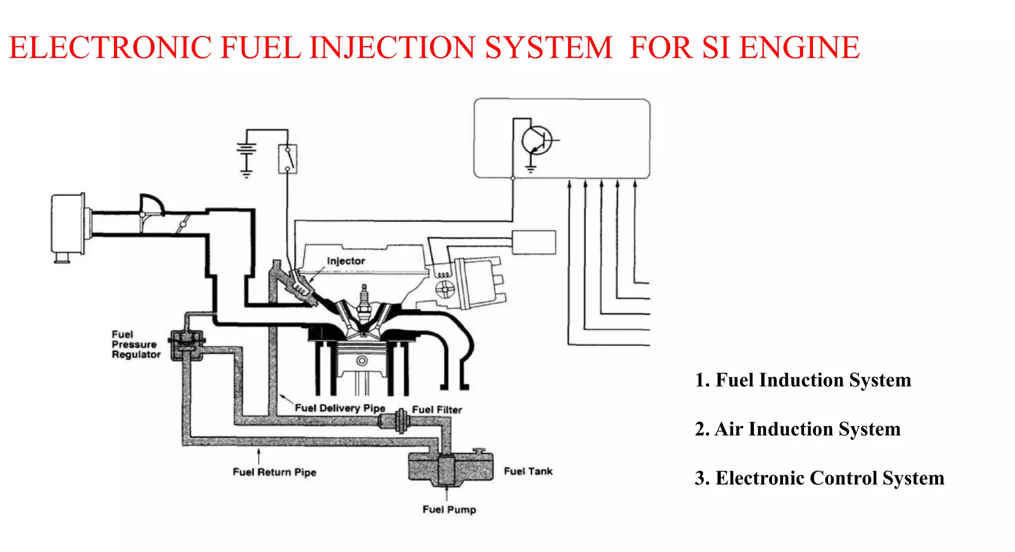
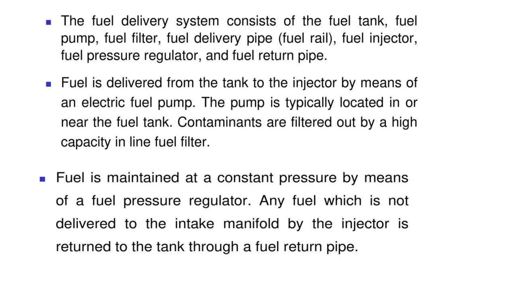
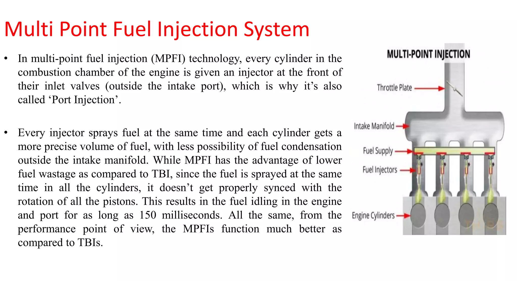
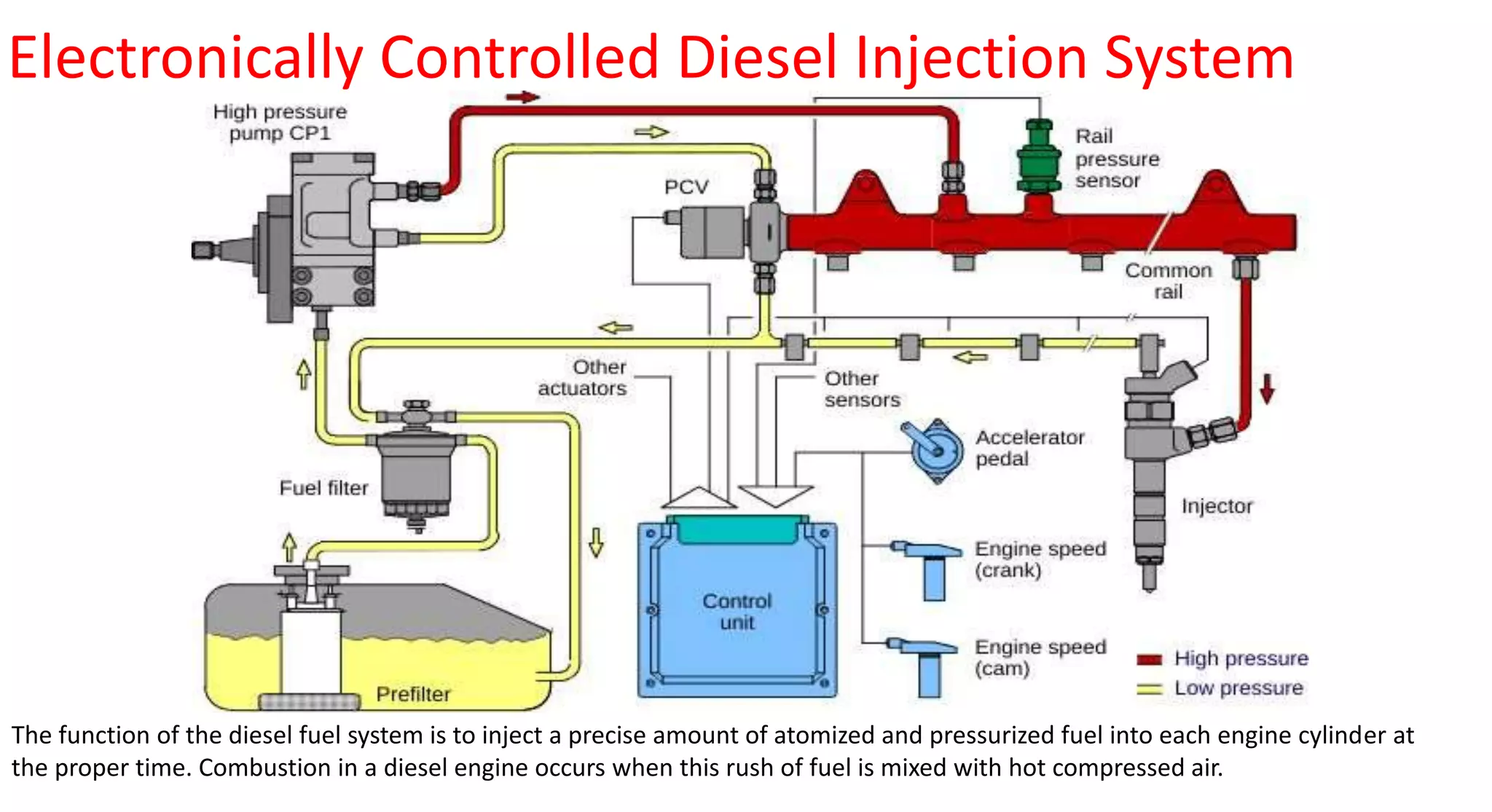
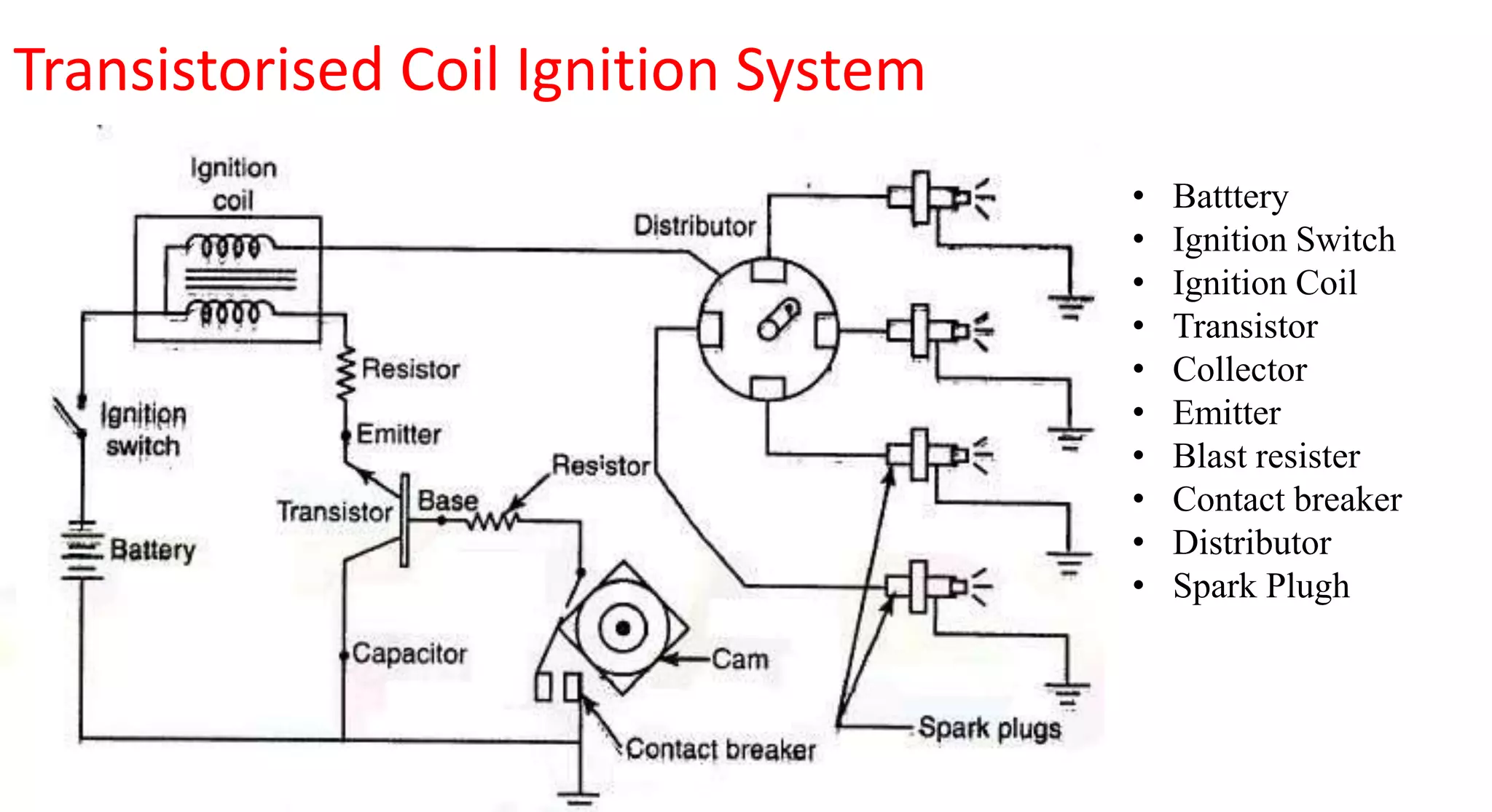
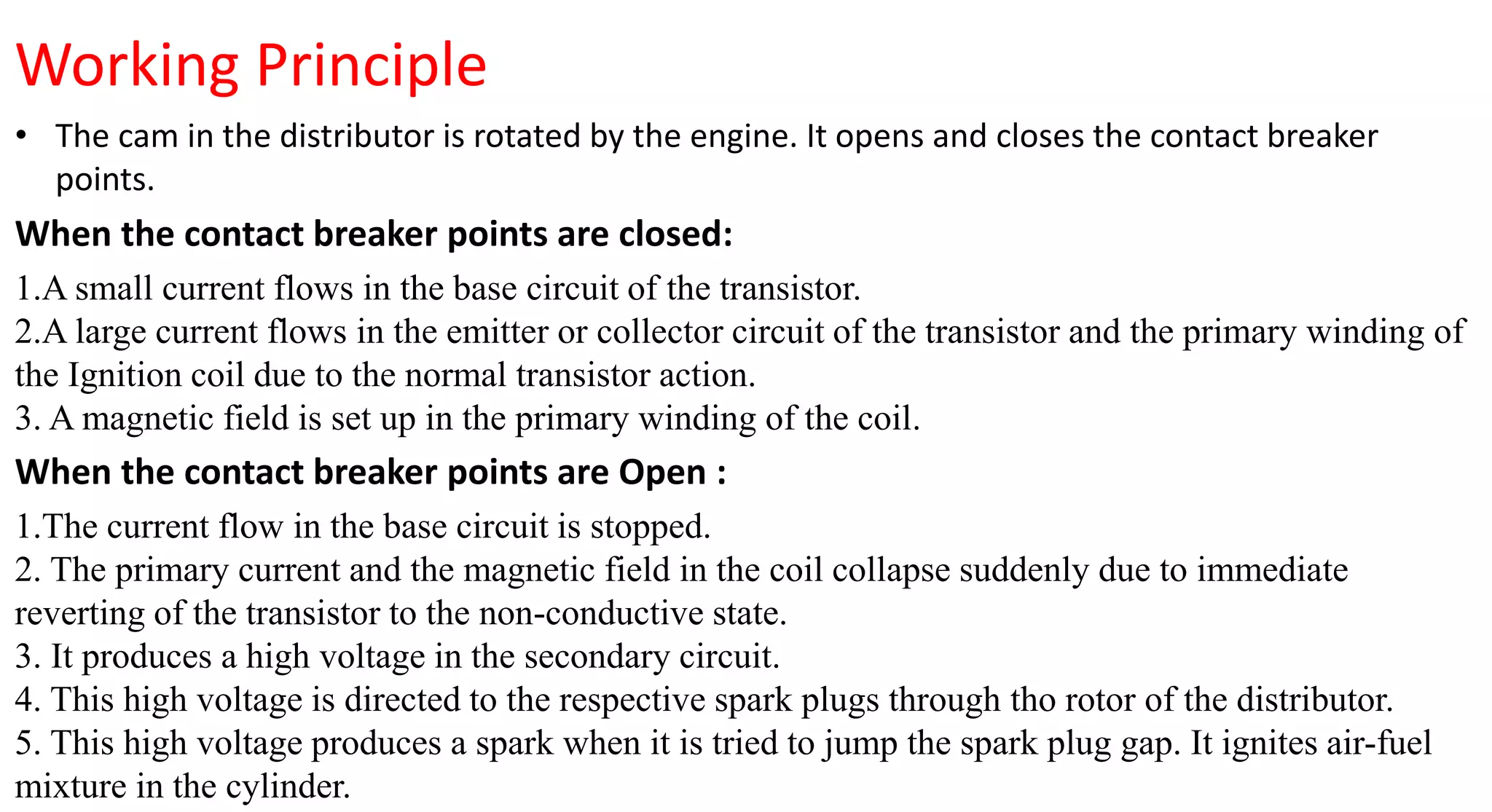
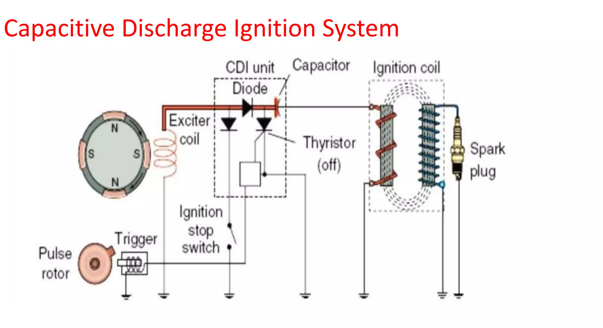
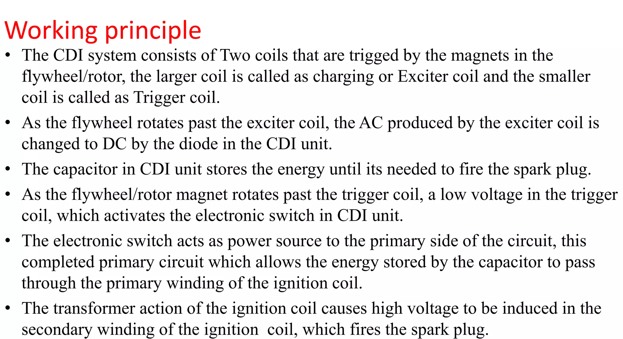
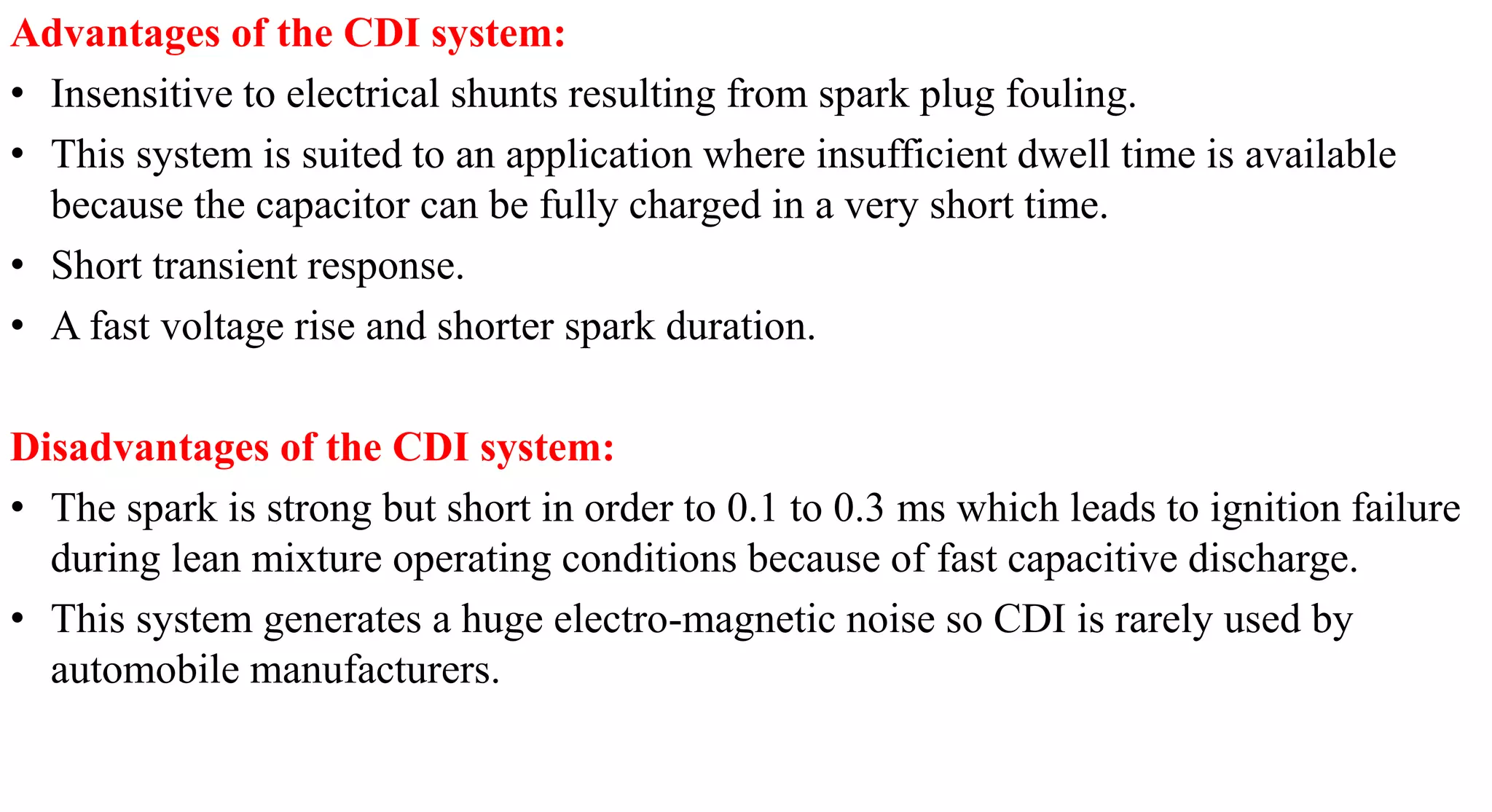
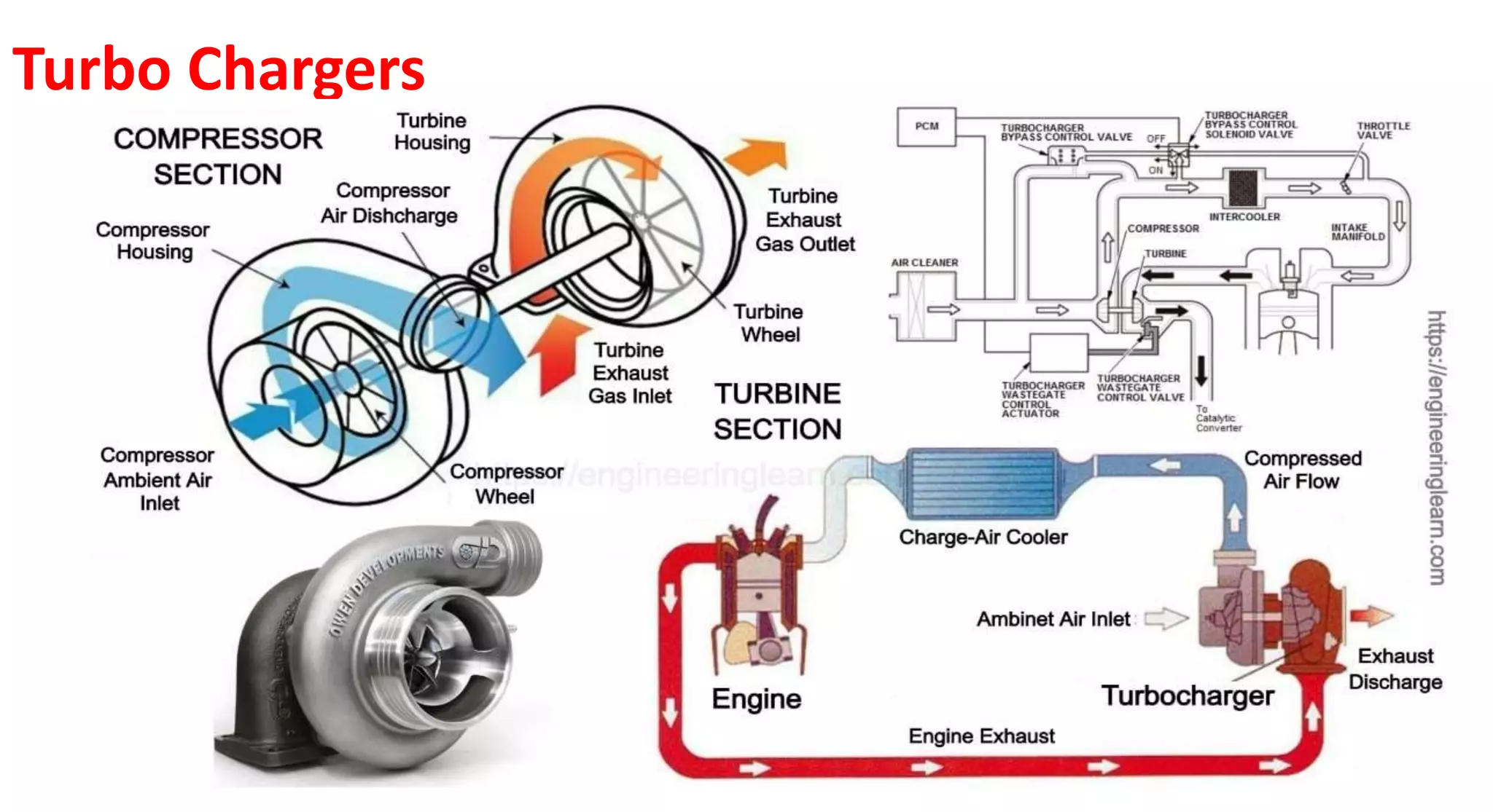
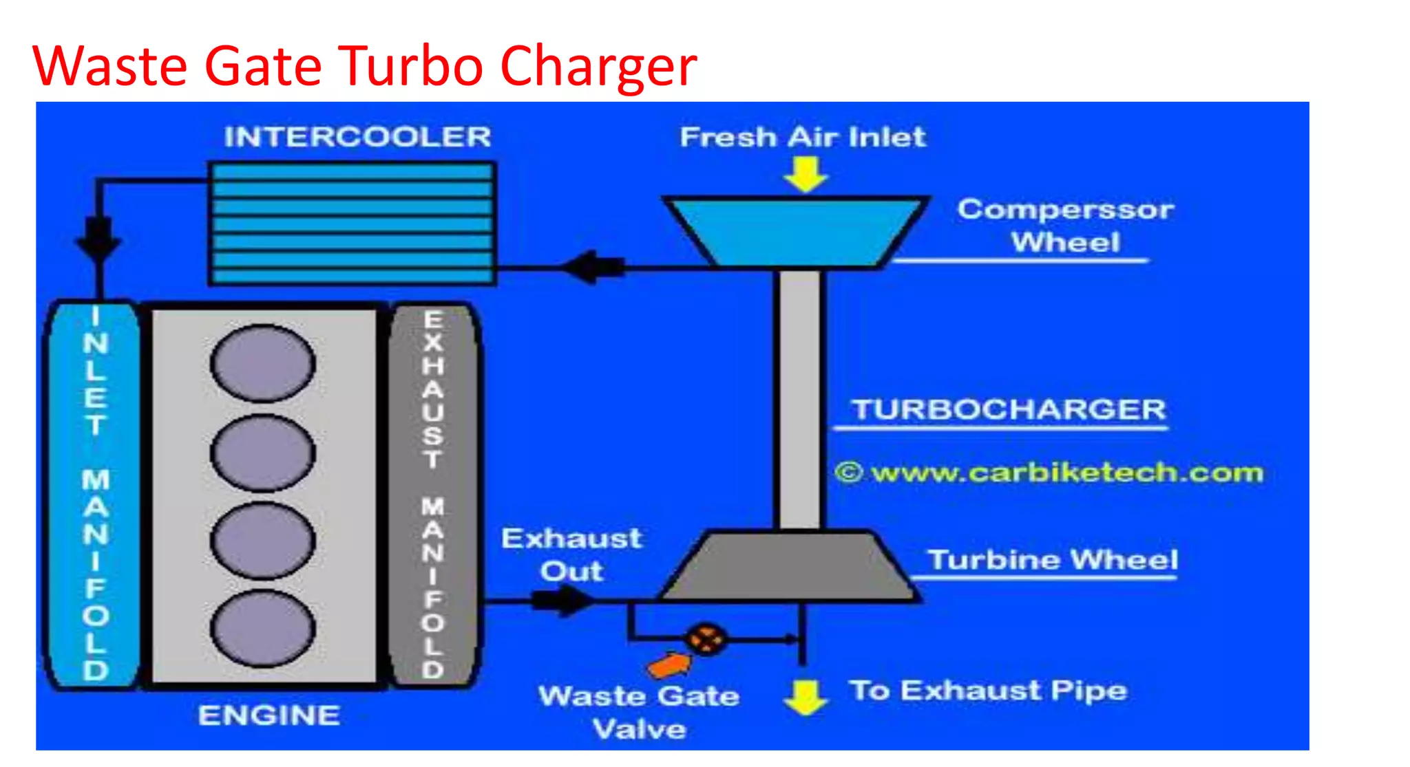
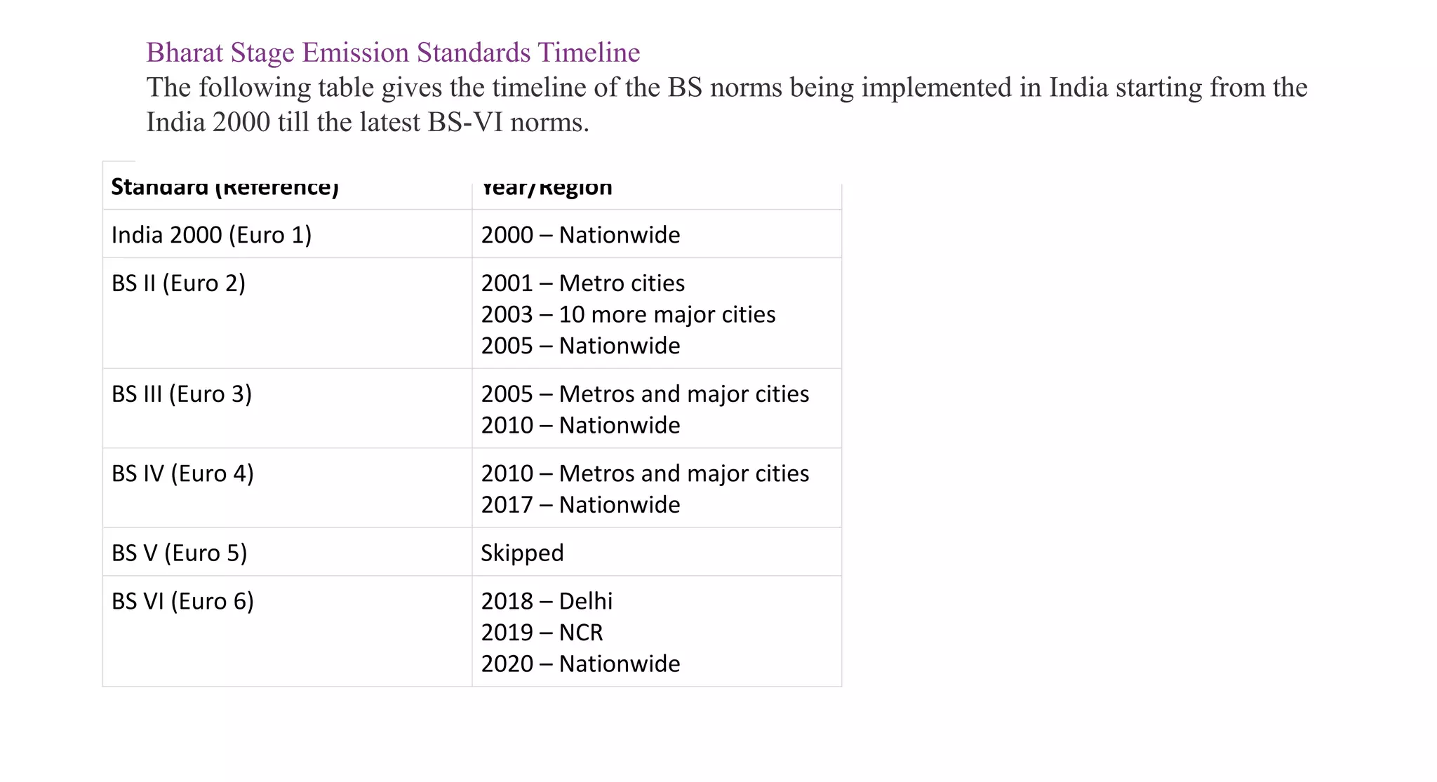

This document provides information on various auxiliary engine systems including electronically controlled fuel injection systems, electronic ignition systems, turbochargers, and emission control systems. It discusses the components, working principles, advantages, and disadvantages of single point and multi-point fuel injection systems, unit injector diesel injection systems, distributor and common rail diesel injection systems, transistorized coil ignition systems, and capacitive discharge ignition systems. It also provides details on wastegate and variable geometry turbochargers and how they regulate boost pressure. Finally, it mentions emission norms and three-way catalytic converter systems for controlling engine emissions.


