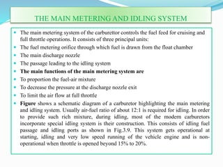
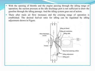
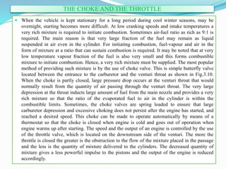
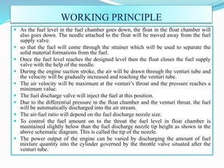
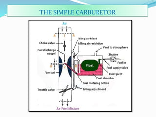
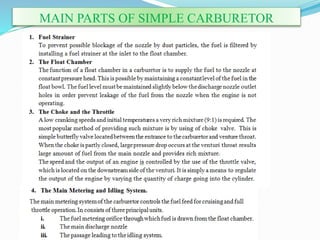
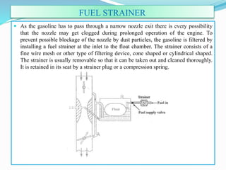
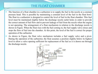
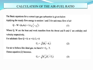
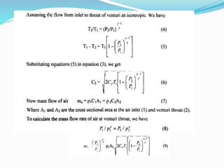
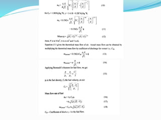
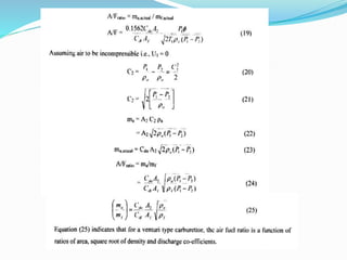
BY
INDRANIL MANDAL
ASSISTANT PROFESSOR
DEPARTMENT-MECHANICAL ENGINEERING
IDEAL INSTITUTE OF ENGINEERING
CARBURETION
ď‚— Spark-ignition engines normally use volatile liquid fuels. Preparation
of fuel-air mixture is done outside the engine cylinder and formation
of a homogeneous mixture is normally not completed in the inlet
manifold. Fuel droplets which remain in suspension continue to
evaporate and mix with air even during suction and compression
processes. The process of mixture preparation is extremely important
for spark-ignition engines. The purpose of carburetion is to
provide a combustible mixture of fuel and air in the required quantity
and quality for efficient operation of the engine under all conditions.
ď‚— The process of mixture preparation in an SI engine is called
carburetion. This air-fuel mixture is prepared outside the cylinder in
a device called CARBURETOR.
ď‚— The carburetor atomizes the fuel and mixes with air in different
proportions for various LOAD conditions.
FUNCTIONS
ď‚— It must atomize, vaporize and mix the fuel homogeneously
with air.
ď‚— It must supply correct amount of air-fuel mixture in
correct proportion under all load conditions and speed of
the engine.
ď‚— It must run the engine smoothly by supplying correct
mixture strength.
ADVANTAGES OF CARBURETOR
ď‚— Carburetor parts are not expensive as that of fuel injectors,
especially EFI, which would give you large savings.
ď‚— With the use of carburetor you get more air and fuel mixture.
ď‚— In terms of road test, carburetors have more power and
precision.
ď‚— Carburetors are not restricted by the amount of gas pumped
from the fuel tank which means that cylinders may pull more
fuel through the carburetor that would lead to denser mixture in
the chamber and greater power as well.
ď‚— At a very low speed, the mixture supplied by a carburetor is so
weak that it will not ignite properly and for its enrichment, at
such conditions some arrangement in the carburetor is required.
ď‚— The working of carburetor is affected by changes of
atmospheric pressure.
ď‚— It gives the proper mixture at only one engine speed and load,
therefore, suitable only for engines running at constant speed
increase or decrease.
ď‚— More fuels are consumed since carburetors are heavier than
fuel injectors.
ď‚— More air emissions than fuel injectors.
ď‚— Maintenance costs of carburetor is higher than with fuel
injection system
DISADVANTAGES OF CARBURETOR
FACTORS AFFECTING CARBURETION
Of the various factors, the process of carburetion is
influenced by
a) The engine speed
b) The vaporization characteristics of the fuel
c) The temperature of the incoming air, and
d) The design of the carburetor
AIR-FUEL MIXTURES
An engine is generally operated at different loads and speeds.
For this, proper air-fuel mixture should be supplied to the
engine cylinder. Fuel and air are mixed to form three different
types of mixtures:
1. Chemically correct or stoichiometric mixture (A/F ratio-
15:1)
2. Rich mixture (A/F ratio- 12:1, 10:1 etc.)
3. Lean mixture (A/F ratio- 17:1, 20:1 etc.)
USEFULA/F MIXTURE RANGE OF GASOLINE
MIXTURE REQUIREMENTS OF SI ENGINE
ď‚— The mixture corresponding to maximum output on the
curve is called best power A/F mixture, which is richer
than the stoichiometric mixture.
ď‚— The mixture corresponding to maximum BSFC on the
curve is called best economy mixture, which is leaner than
the stoichiometric mixture.
 • The actual A/F ratio requirement for an automative
carburetor falls in 3 ranges:
ď‚— Idling (rich)
ď‚— Cruising (lean)
ď‚— High Power (rich)
MIXTURE REQUIREMENTS AT DIFFERENT ENGINE CONDITIONS
ď‚— Idling Range (1-2)
ď‚— During idling, engine operates at no load and closed throttle.
ď‚— The engine requires rich mixture for starting at idling.
ď‚— Rich mixture is required to compensate for the charge dilution due to
exhaust gases from the combustion chamber.
ď‚— Also, the amount of fresh charge admitted is less due to smaller
throttle opening.
ď‚— Exhaust gas dilution prevents efficient combustion by reducing the
contact between the fuel and air particles.
ď‚— Rich mixture improves the contact of fuel and air by providing
efficient combustion at idling conditions.
ď‚— As the throttle is opened further, the exhaust gas dilution reduces and
the mixture requirement shifts to the leaner side.
ď‚— Cruising Range (2-3)
ď‚— Focus is on fuel economy.
ď‚— No exhaust gas dilution.
ď‚— Carburetor has to give best economy mixture i.e.. Lean
mixture.
ď‚— High Power Range (3-4)
ď‚— As high power is required, additional fuel has to be
supplied to achieve rich mixture in this range.
 • Rich mixture also prevents overheating by reducing the
flame temperature and cylinder temperature.
PRINCIPLE OF CARBURETION
ď‚— Both air and gasoline are drawn through the carburetor and into the engine
cylinders by the suction created by the downward movement of the piston.
This suction is due to an increase in the volume of the cylinder and a
consequent decrease in the gas pressure in this chamber. It is the difference
in pressure between the atmosphere and cylinder that causes the air to flow
into the chamber. In the carburetor, air passing into the combustion cham-
ber picks up fuel discharged from a tube. This tube has a fine orifice called
carburetor jet which is exposed to the air path. The rate at which fuel is
discharged into the air depends on the pressure difference or pressure head
between the float chamber and the throat of the venturi and on the area of
the outlet of the tube. In order that the fuel drawn from the nozzle may be
thoroughly atomized, the suction effect must be strong and the nozzle outlet
comparatively small. In order to produce a strong suction, the pipe in the
carburetor carrying air to the engine is made to have a restriction. At this
restriction called throat due to increase in velocity of flow, a suction effect is
created. The restriction is made in the form of a venturi as shown in Figure
to minimize throttling losses. The end of the fuel jet is located at the venturi
or throat of the carburetor.
OPERATION OF THE VENTURI TUBE
The geometry of venturi tube is as shown in Figure. It has a narrower path at the
centre so that the flow area through which the air must pass is considerably reduced.
As the same amount of air must pass through every point in the tube, its velocity will
be greatest at the narrowest point. The smaller the area, the greater will be the
velocity of the air, and thereby the suction is proportionately increased
ď‚— As mentioned earlier, the opening of the fuel discharge jet is usually located
where the suction is maximum. Normally, this is just below the narrowest
section of the venturi tube. The spray of gasoline from the nozzle and the air
entering through the venturi tube are mixed together in this region and a
combustible mixture is formed which passes through the intake manifold
into the cylinders. Most of the fuel gets atomized and simultaneously a
small part will be vapourized. Increased air velocity at the throat of the
venturi helps the rate of evaporation of fuel. The difficulty of obtaining a
mixture of sufficiently high fuel vapour-air ratio for efficient starting of the
engine and for uniform fuel-air ratio in different cylinders (in case of multi-
cylinder engine) cannot be fully met by the increased air velocity alone at
the venturi throat.
THE SIMPLE CARBURETOR
MAIN PARTS OF SIMPLE CARBURETOR
FUEL STRAINER
ď‚— As the gasoline has to pass through a narrow nozzle exit there is every possibility
that the nozzle may get clogged during prolonged operation of the engine. To
prevent possible blockage of the nozzle by dust particles, the gasoline is filtered by
installing a fuel strainer at the inlet to the float chamber. The strainer consists of a
fine wire mesh or other type of filtering device, cone shaped or cylindrical shaped.
The strainer is usually removable so that it can be taken out and cleaned thoroughly.
It is retained in its seat by a strainer plug or a compression spring.
THE FLOAT CHAMBER
ď‚— The function of a float chamber in a carburetor is to supply the fuel to the nozzle at a constant
pressure head. This is possible by maintaining a constant level of the fuel in the float bowl.
The float in a carburetor is designed to control the level of fuel in the float chamber. This fuel
level must be maintained slightly below the discharge nozzle outlet holes in order to provide
the correct amount of fuel flow and to prevent leakage of fuel from the nozzle when the engine
is not operating. The arrangement of a float mechanism in relation to the discharge nozzle is
shown in Figure. When the float rises with the fuel coming in, the fuel supply valve closes and
stops the flow of fuel into the chamber. At this point, the level of the fuel is correct for proper
operation of the carburetor.
ď‚— As shown in Figure, the float valve mechanism includes a fuel supply valve and a pivot.
During the operation of the carburetor, the float assumes a position slightly below its highest
level to allow a valve opening sufficient for replacement of the fuel as it is drawn out through
the discharge nozzle.
THE MAIN METERING AND IDLING SYSTEM
ď‚— The main metering system of the carburettor controls the fuel feed for cruising and
full throttle operations. It consists of three principal units:
ď‚— The fuel metering orifice through which fuel is drawn from the float chamber
ď‚— The main discharge nozzle
ď‚— The passage leading to the idling system
ď‚— The main functions of the main metering system are
ď‚— To proportion the fuel-air mixture
ď‚— To decrease the pressure at the discharge nozzle exit
ď‚— To limit the air flow at full throttle
ď‚— Figure shows a schematic diagram of a carburetor highlighting the main metering
and idling system. Usually air-fuel ratio of about 12:1 is required for idling. In order
to provide such rich mixture, during idling, most of the modern carburetors
incorporate special idling system is their construction. This consists of idling fuel
passage and idling ports as shown in Fig.3.9. This system gets operational at
starting, idling and very low speed running of the vehicle engine and is non-
operational when throttle is opened beyond 15% to 20%.
ď‚— With the opening of throttle and the engine passing through the idling range of
operation, the suction pressure at the idle discharge port is not sufficient to draw the
gasoline through the idling passage. And the idling system goes out of action.
ď‚— There after main air flow increases and the cruising range of operation is
established. The desired fuel-air ratio for idling can be regulated by idling
adjustment shown in Figure.
THE CHOKE AND THE THROTTLE
ď‚— When the vehicle is kept stationary for a long period during cool winter seasons, may be
overnight, starting becomes more difficult. At low cranking speeds and intake temperatures a
very rich mixture is required to initiate combustion. Sometimes air-fuel ratio as rich as 9:1 is
required. The main reason is that very large fraction of the fuel may remain as liquid
suspended in air even in the cylinder. For initiating combustion, fuel-vapour and air in the
form of mixture at a ratio that can sustain combustion is required. It may be noted that at very
low temperature vapour fraction of the fuel is also very small and this forms combustible
mixture to initiate combustion. Hence, a very rich mixture must be supplied. The most popular
method of providing such mixture is by the use of choke valve. This is simple butterfly valve
located between the entrance to the carburetor and the venturi throat as shown in Fig.3.10.
When the choke is partly closed, large pressure drop occurs at the venturi throat that would
normally result from the quantity of air passing through the venturi throat. The very large
depression at the throat inducts large amount of fuel from the main nozzle and provides a very
rich mixture so that the ratio of the evaporated fuel to air in the cylinder is within the
combustible limits. Sometimes, the choke valves are spring loaded to ensure that large
carburetor depression and excessive choking does not persist after the engine has started, and
reached a desired speed. This choke can be made to operate automatically by means of a
thermostat so that the choke is closed when engine is cold and goes out of operation when
engine warms up after starting. The speed and the output of an engine is controlled by the use
of the throttle valve, which is located on the downstream side of the venturi. The more the
throttle is closed the greater is the obstruction to the flow of the mixture placed in the passage
and the less is the quantity of mixture delivered to the cylinders. The decreased quantity of
mixture gives a less powerful impulse to the pistons and the output of the engine is reduced
accordingly.
WORKING PRINCIPLE
ď‚— As the fuel level in the fuel chamber goes down, the float in the float chamber will
also goes down. The needle attached to the float will be moved away from the fuel
supply valve.
ď‚— so that the fuel will come through the strainer which will be used to separate the
solid material formations from the fuel.
ď‚— Once the fuel level reaches the designed level then the float closes the fuel supply
valve with the help of the needle.
ď‚— During the engine suction stroke, the air will be drawn through the venturi tube and
the velocity will be gradually increased and reaching the venturi tube.
 The air velocity will be maximum at the venturi’s throat and the pressure reaches a
minimum value.
ď‚— The fuel discharge valve will inject the fuel at this position.
ď‚— Due to the differential pressure in the float chamber and the venturi throat, the fuel
will be automatically discharged into the air stream.
ď‚— The air-fuel ratio will depend on the fuel discharge nozzle size.
ď‚— To control the fuel amount on to the throat the fuel level in float chamber is
maintained slightly below than the fuel discharge nozzle tip height as shown in the
above schematic diagram. This is called the tip of the nozzle.
ď‚— The power output of the engine can be varied by discharging the amount of fuel
mixture quantity into the cylinder governed by the throttle valve situated after the
venturi tube.
CALCULATION OF THE AIR-FUEL RATIO
THANK YOU

Carburetion

  • 1.
    BY INDRANIL MANDAL ASSISTANT PROFESSOR DEPARTMENT-MECHANICALENGINEERING IDEAL INSTITUTE OF ENGINEERING
  • 2.
    CARBURETION ď‚— Spark-ignition enginesnormally use volatile liquid fuels. Preparation of fuel-air mixture is done outside the engine cylinder and formation of a homogeneous mixture is normally not completed in the inlet manifold. Fuel droplets which remain in suspension continue to evaporate and mix with air even during suction and compression processes. The process of mixture preparation is extremely important for spark-ignition engines. The purpose of carburetion is to provide a combustible mixture of fuel and air in the required quantity and quality for efficient operation of the engine under all conditions. ď‚— The process of mixture preparation in an SI engine is called carburetion. This air-fuel mixture is prepared outside the cylinder in a device called CARBURETOR. ď‚— The carburetor atomizes the fuel and mixes with air in different proportions for various LOAD conditions.
  • 3.
    FUNCTIONS ď‚— It mustatomize, vaporize and mix the fuel homogeneously with air. ď‚— It must supply correct amount of air-fuel mixture in correct proportion under all load conditions and speed of the engine. ď‚— It must run the engine smoothly by supplying correct mixture strength.
  • 4.
    ADVANTAGES OF CARBURETOR ď‚—Carburetor parts are not expensive as that of fuel injectors, especially EFI, which would give you large savings. ď‚— With the use of carburetor you get more air and fuel mixture. ď‚— In terms of road test, carburetors have more power and precision. ď‚— Carburetors are not restricted by the amount of gas pumped from the fuel tank which means that cylinders may pull more fuel through the carburetor that would lead to denser mixture in the chamber and greater power as well.
  • 5.
    ď‚— At avery low speed, the mixture supplied by a carburetor is so weak that it will not ignite properly and for its enrichment, at such conditions some arrangement in the carburetor is required. ď‚— The working of carburetor is affected by changes of atmospheric pressure. ď‚— It gives the proper mixture at only one engine speed and load, therefore, suitable only for engines running at constant speed increase or decrease. ď‚— More fuels are consumed since carburetors are heavier than fuel injectors. ď‚— More air emissions than fuel injectors. ď‚— Maintenance costs of carburetor is higher than with fuel injection system DISADVANTAGES OF CARBURETOR
  • 6.
    FACTORS AFFECTING CARBURETION Ofthe various factors, the process of carburetion is influenced by a) The engine speed b) The vaporization characteristics of the fuel c) The temperature of the incoming air, and d) The design of the carburetor
  • 7.
    AIR-FUEL MIXTURES An engineis generally operated at different loads and speeds. For this, proper air-fuel mixture should be supplied to the engine cylinder. Fuel and air are mixed to form three different types of mixtures: 1. Chemically correct or stoichiometric mixture (A/F ratio- 15:1) 2. Rich mixture (A/F ratio- 12:1, 10:1 etc.) 3. Lean mixture (A/F ratio- 17:1, 20:1 etc.)
  • 8.
  • 9.
    MIXTURE REQUIREMENTS OFSI ENGINE  The mixture corresponding to maximum output on the curve is called best power A/F mixture, which is richer than the stoichiometric mixture.  The mixture corresponding to maximum BSFC on the curve is called best economy mixture, which is leaner than the stoichiometric mixture.  • The actual A/F ratio requirement for an automative carburetor falls in 3 ranges:  Idling (rich)  Cruising (lean)  High Power (rich)
  • 11.
    MIXTURE REQUIREMENTS ATDIFFERENT ENGINE CONDITIONS
  • 12.
    ď‚— Idling Range(1-2) ď‚— During idling, engine operates at no load and closed throttle. ď‚— The engine requires rich mixture for starting at idling. ď‚— Rich mixture is required to compensate for the charge dilution due to exhaust gases from the combustion chamber. ď‚— Also, the amount of fresh charge admitted is less due to smaller throttle opening. ď‚— Exhaust gas dilution prevents efficient combustion by reducing the contact between the fuel and air particles. ď‚— Rich mixture improves the contact of fuel and air by providing efficient combustion at idling conditions. ď‚— As the throttle is opened further, the exhaust gas dilution reduces and the mixture requirement shifts to the leaner side.
  • 13.
     Cruising Range(2-3)  Focus is on fuel economy.  No exhaust gas dilution.  Carburetor has to give best economy mixture i.e.. Lean mixture.  High Power Range (3-4)  As high power is required, additional fuel has to be supplied to achieve rich mixture in this range.  • Rich mixture also prevents overheating by reducing the flame temperature and cylinder temperature.
  • 14.
    PRINCIPLE OF CARBURETION ď‚—Both air and gasoline are drawn through the carburetor and into the engine cylinders by the suction created by the downward movement of the piston. This suction is due to an increase in the volume of the cylinder and a consequent decrease in the gas pressure in this chamber. It is the difference in pressure between the atmosphere and cylinder that causes the air to flow into the chamber. In the carburetor, air passing into the combustion cham- ber picks up fuel discharged from a tube. This tube has a fine orifice called carburetor jet which is exposed to the air path. The rate at which fuel is discharged into the air depends on the pressure difference or pressure head between the float chamber and the throat of the venturi and on the area of the outlet of the tube. In order that the fuel drawn from the nozzle may be thoroughly atomized, the suction effect must be strong and the nozzle outlet comparatively small. In order to produce a strong suction, the pipe in the carburetor carrying air to the engine is made to have a restriction. At this restriction called throat due to increase in velocity of flow, a suction effect is created. The restriction is made in the form of a venturi as shown in Figure to minimize throttling losses. The end of the fuel jet is located at the venturi or throat of the carburetor.
  • 15.
    OPERATION OF THEVENTURI TUBE The geometry of venturi tube is as shown in Figure. It has a narrower path at the centre so that the flow area through which the air must pass is considerably reduced. As the same amount of air must pass through every point in the tube, its velocity will be greatest at the narrowest point. The smaller the area, the greater will be the velocity of the air, and thereby the suction is proportionately increased
  • 16.
    ď‚— As mentionedearlier, the opening of the fuel discharge jet is usually located where the suction is maximum. Normally, this is just below the narrowest section of the venturi tube. The spray of gasoline from the nozzle and the air entering through the venturi tube are mixed together in this region and a combustible mixture is formed which passes through the intake manifold into the cylinders. Most of the fuel gets atomized and simultaneously a small part will be vapourized. Increased air velocity at the throat of the venturi helps the rate of evaporation of fuel. The difficulty of obtaining a mixture of sufficiently high fuel vapour-air ratio for efficient starting of the engine and for uniform fuel-air ratio in different cylinders (in case of multi- cylinder engine) cannot be fully met by the increased air velocity alone at the venturi throat.
  • 17.
  • 18.
    MAIN PARTS OFSIMPLE CARBURETOR
  • 19.
    FUEL STRAINER ď‚— Asthe gasoline has to pass through a narrow nozzle exit there is every possibility that the nozzle may get clogged during prolonged operation of the engine. To prevent possible blockage of the nozzle by dust particles, the gasoline is filtered by installing a fuel strainer at the inlet to the float chamber. The strainer consists of a fine wire mesh or other type of filtering device, cone shaped or cylindrical shaped. The strainer is usually removable so that it can be taken out and cleaned thoroughly. It is retained in its seat by a strainer plug or a compression spring.
  • 20.
    THE FLOAT CHAMBER ď‚—The function of a float chamber in a carburetor is to supply the fuel to the nozzle at a constant pressure head. This is possible by maintaining a constant level of the fuel in the float bowl. The float in a carburetor is designed to control the level of fuel in the float chamber. This fuel level must be maintained slightly below the discharge nozzle outlet holes in order to provide the correct amount of fuel flow and to prevent leakage of fuel from the nozzle when the engine is not operating. The arrangement of a float mechanism in relation to the discharge nozzle is shown in Figure. When the float rises with the fuel coming in, the fuel supply valve closes and stops the flow of fuel into the chamber. At this point, the level of the fuel is correct for proper operation of the carburetor. ď‚— As shown in Figure, the float valve mechanism includes a fuel supply valve and a pivot. During the operation of the carburetor, the float assumes a position slightly below its highest level to allow a valve opening sufficient for replacement of the fuel as it is drawn out through the discharge nozzle.
  • 21.
    THE MAIN METERINGAND IDLING SYSTEM ď‚— The main metering system of the carburettor controls the fuel feed for cruising and full throttle operations. It consists of three principal units: ď‚— The fuel metering orifice through which fuel is drawn from the float chamber ď‚— The main discharge nozzle ď‚— The passage leading to the idling system ď‚— The main functions of the main metering system are ď‚— To proportion the fuel-air mixture ď‚— To decrease the pressure at the discharge nozzle exit ď‚— To limit the air flow at full throttle ď‚— Figure shows a schematic diagram of a carburetor highlighting the main metering and idling system. Usually air-fuel ratio of about 12:1 is required for idling. In order to provide such rich mixture, during idling, most of the modern carburetors incorporate special idling system is their construction. This consists of idling fuel passage and idling ports as shown in Fig.3.9. This system gets operational at starting, idling and very low speed running of the vehicle engine and is non- operational when throttle is opened beyond 15% to 20%.
  • 22.
    ď‚— With theopening of throttle and the engine passing through the idling range of operation, the suction pressure at the idle discharge port is not sufficient to draw the gasoline through the idling passage. And the idling system goes out of action. ď‚— There after main air flow increases and the cruising range of operation is established. The desired fuel-air ratio for idling can be regulated by idling adjustment shown in Figure.
  • 23.
    THE CHOKE ANDTHE THROTTLE ď‚— When the vehicle is kept stationary for a long period during cool winter seasons, may be overnight, starting becomes more difficult. At low cranking speeds and intake temperatures a very rich mixture is required to initiate combustion. Sometimes air-fuel ratio as rich as 9:1 is required. The main reason is that very large fraction of the fuel may remain as liquid suspended in air even in the cylinder. For initiating combustion, fuel-vapour and air in the form of mixture at a ratio that can sustain combustion is required. It may be noted that at very low temperature vapour fraction of the fuel is also very small and this forms combustible mixture to initiate combustion. Hence, a very rich mixture must be supplied. The most popular method of providing such mixture is by the use of choke valve. This is simple butterfly valve located between the entrance to the carburetor and the venturi throat as shown in Fig.3.10. When the choke is partly closed, large pressure drop occurs at the venturi throat that would normally result from the quantity of air passing through the venturi throat. The very large depression at the throat inducts large amount of fuel from the main nozzle and provides a very rich mixture so that the ratio of the evaporated fuel to air in the cylinder is within the combustible limits. Sometimes, the choke valves are spring loaded to ensure that large carburetor depression and excessive choking does not persist after the engine has started, and reached a desired speed. This choke can be made to operate automatically by means of a thermostat so that the choke is closed when engine is cold and goes out of operation when engine warms up after starting. The speed and the output of an engine is controlled by the use of the throttle valve, which is located on the downstream side of the venturi. The more the throttle is closed the greater is the obstruction to the flow of the mixture placed in the passage and the less is the quantity of mixture delivered to the cylinders. The decreased quantity of mixture gives a less powerful impulse to the pistons and the output of the engine is reduced accordingly.
  • 24.
    WORKING PRINCIPLE  Asthe fuel level in the fuel chamber goes down, the float in the float chamber will also goes down. The needle attached to the float will be moved away from the fuel supply valve.  so that the fuel will come through the strainer which will be used to separate the solid material formations from the fuel.  Once the fuel level reaches the designed level then the float closes the fuel supply valve with the help of the needle.  During the engine suction stroke, the air will be drawn through the venturi tube and the velocity will be gradually increased and reaching the venturi tube.  The air velocity will be maximum at the venturi’s throat and the pressure reaches a minimum value.  The fuel discharge valve will inject the fuel at this position.  Due to the differential pressure in the float chamber and the venturi throat, the fuel will be automatically discharged into the air stream.  The air-fuel ratio will depend on the fuel discharge nozzle size.  To control the fuel amount on to the throat the fuel level in float chamber is maintained slightly below than the fuel discharge nozzle tip height as shown in the above schematic diagram. This is called the tip of the nozzle.  The power output of the engine can be varied by discharging the amount of fuel mixture quantity into the cylinder governed by the throttle valve situated after the venturi tube.
  • 25.
    CALCULATION OF THEAIR-FUEL RATIO
  • 29.