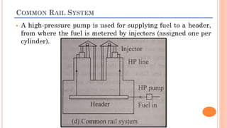
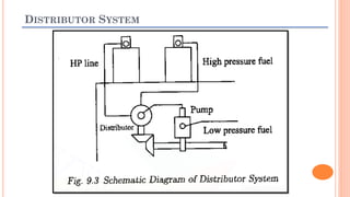
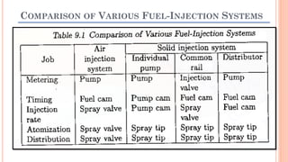
2. INTRODUCTION
The fuel injection system is the most vital component
in the working of CI engines.
The engine performance is greatly dependent on the
effectiveness of fuel injection system.
The injection system has to perform the important
duty of initiating and controlling the combustion
process.
3. COMPARISON BETWEEN CARBURETOR & MECHANICAL
INJECTION SYSTEMS
Purpose of Carburetion and Fuel Injection = Preparation of combustible
charge but there is some difference:
Carburetion Fuel injection
Air Speed is greater than fuel
speed at fuel nozzle to atomize
the fuel
Fuel Speed is greater than Air
speed at the delivery point to
atomize the fuel
The amount of fuel drawn into
the engine depends upon
the air velocity in the venturi
The amount of fuel delivered
into the air stream going to
the engine is controlled by a
pump which forces the fuel
under pressure
4. FUNCTIONAL REQUIREMENTS OF INJECTION SYSTEM
1) Accurate metering of the fuel injected per cycle. This is
very critical due to the fact that very small quantities of
fuel being handled. Metering errors may cause drastic
variation from the desired output. The quantity of the fuel
metered should vary to meet speed and load requirements
of the engine.
2) Timing the injection of the fuel correctly in the cycle to
obtain maximum power; ensuring fuel economy and clean
burning.
3) Proper control of rate of injection so that the desired heat
release pattern is achieved during combustion.
4) Proper atomization of fuel into very fine droplets.
5. FUNCTIONAL REQUIREMENTS OF INJECTION SYSTEM
5) Proper spray pattern to ensure rapid mixing of fuel and
air
6) Uniform distribution of fuel droplets throughout the
combustion chamber.
7) To supply equal quantities of metered fuel to all
cylinders in case of multi cylinder engines.
8) No lag during beginning and end of injection i.e. to
eliminate dribbling of fuel droplets into the cylinder.
6. CLASSIFICATIONS OF INJECTION SYSTEMS
A fuel-injection system is required to inject and atomize fuel into
the cylinder of CI engines.
For producing the required pressure for atomizing the fuel either
air or a mechanical means is used.
Thus the injection systems can be classified as:
Air injection system
Solid injection systems
7. AIR INJECTION SYSTEM
In this system, fuel is forced into the cylinder by means of compressed
air.
Advantages:
1- Good mixing of fuel with the air
2- Higher MEP
3- It has the ability to utilize high viscosity
(less expensive) fuels
Disadvantages:
1- The requirement of bulky multistage air
compressor making air injection system
obsolete
8. SOLID (AIRLESS MECHANICAL) INJECTION SYSTEM
In this system, the liquid fuel is injected directly into the combustion
chamber without the aid of compressed air. Hence, it is also called
airless mechanical injection (or) solid injection system.
Solid injection systems can be classified into four types:
1) Individual Pump and Nozzle Systems
2) Unit Injector Systems
3) Common Rail Systems
4) Distributor Systems
9. MAIN COMPONENTS OF MECHANICAL INJECTION SYSTEMS
All the injection systems (mentioned in slide # 08) mainly comprise of
the following components.
1) Fuel tank
2) Fuel feed pump to supply fuel from the main fuel tank to the
injection system
3) Injection pump to meter and pressurize the fuel for injection
4) Governor to ensure that the amount of fuel injected is in
accordance with the variation in load
5) Injector to take the fuel from the pump and distribute it in the
combustion chamber by atomizing it into fine droplets
6) Fuel filters to prevent dust and abrasive particles from entering the
pump and injectors thereby minimizing the wear and tear of the
components
11. WORKING OF MECHANICAL INJECTION SYSTEMS
Fuel from the fuel tank first enters the coarse filter from which it is
drawn into the plunger feed pump where the pressure is raised very
slightly.
Now the fuel enters the fine filter where all the dust & dirt particles
are removed.
From the fine filters the fuel enters the fuel feed pump where it is
pressurized to about 200 bar & injected into the engine cylinder by
means of injector.
Any spill over in the injector is returned to fine filter. A pressure
relief valve is also provided for the safety of system.
12. INDIVIDUAL PUMP AND NOZZLE SYSTEMS
In this system, each cylinder is provided with
one pump and one injector.
In this arrangement a separate metering and
compression pump is provided for each cylinder.
The pump may be placed close to the cylinder
(fig. a) or they may be arranged in a cluster (fig.
b) .
The high-pressure pump plunger is actuated by
a cam and produces the fuel pressure necessary
to open the injector valve at the correct time.
The amount of fuel injected depends on the
effective stroke of the plunger.
13. UNIT INJECTOR SYSTEM
The unit injector system is one in which the
pump and the injector nozzle are combined in
one housing.
Each cylinder is provided with one of these unit
injectors.
Fuel is brought up to the injector by a low-
pressure feed pump, where at the proper time,
a rocker arm actuates the plunger and thus
injects the fuel into the cylinder.
The amount of fuel injected is regulated by the
effective stroke of the plunger.
The pump and the injector can be integrated in
on unit as shown in figure (c).
14. COMMON RAIL SYSTEM
In the common rail system, a HP system supplies fuel, under high
pressure, to a fuel header.
High pressure in the header forces the fuel to each of the nozzles
located in the cylinders.
At the proper time, a mechanically operated (by means of a push
rod and rocker arm) valve allows the fuel to enter the proper
cylinder through nozzle.
The pressure in the fuel header must be that, for which the
injector system was designed, i.e. it must be enable to penetrate
and disperse the fuel in the combustion chamber.
The amount of fuel entering the cylinder is regulated by varying
the length of the push rod stroke
15. COMMON RAIL SYSTEM
A high-pressure pump is used for supplying fuel to a header,
from where the fuel is metered by injectors (assigned one per
cylinder).
16. DISTRIBUTOR SYSTEM
In this system the pump which pressurizes the fuel also meters
and times it.
The fuel pump after metering the required amount of fuel supplies
it to a rotating distributor at the correct time for supply to each
cylinder.
The number of injection strokes per cycle for the pump is equal to
the number of cylinders.
Since there is one metering element in each pump, a uniform
distribution is automatically ensured. Not only that, the cost of
the fuel injection system also reduces to a value less than two-
thirds of that for individual pump system.
19. FUEL FEED PUMP
It is of spring-loaded plunger type.
The plunger is actuated through a push
rod from the cam shaft.
At the minimum lift position of the cam
the spring force on the plunger creates a
suction which causes fuel flow from the
main tank into the pump.
When the cam is turned to its maximum
lift position, the plunger is lifted upwards.
At the same time the inlet valve is closed,
and the fuel is forced through the outlet
valves.
20. INJECTION PUMP
The main objectives of fuel-injection pump is to deliver accurately
metered quantity of fuel under high pressure (in the range from
120 to 200 bar) at the correct instant to the injector fitted on each
cylinder.
Injection pumps are of two types:
1) Jerk Type Pumps
2) Distributor Type Pumps
22. JERK TYPE PUMP
It consist of the reciprocating plunger
inside a barrel. The plunger is driven by
camshaft.
(a) A sketch of typical plunger is shown.
(b) Near the port A, fuel is always available
under relatively low pressure. While the
axial movement of the plunger is through
camshafts, its rotational movement
about its axis by means of rack D. Port B
is orifice through which fuel is delivered
to injector.
When the plunger is below port A, the
fuel gets filled in the barrel above it. As
the plunger rises & closes the port A the
fuel will flow out through port C.
23. JERK TYPE PUMP
(c) At this stage, the rack rotates the plunger
& as a result port C also closes. The only
escape route for the fuel is past the check
valve through this orifice B to the injector.
This is the beginning of the injection &
also effective stroke of plunger.
(d) The injection continues till the helical
indentation on the plunger uncovers port
C. Now the fuel will take the easy way out
through C and the check valve will close
the orifice B. The fuel injection stops &
the effective stroke ends. Hence the
effective stroke of the plunger is the axial
distance traversed between the time port
A is closed off & the time port A is
uncovered.
24. JERK TYPE PUMP
(e) & (f) The plunger is rotated to the
position shown. The same sequence of
events occur. But in this case C is
uncovered sooner. Hence the effective
stroke is shortened.
It is important to remember here that
though the axial distance traversed by
the plunger is same for every stroke,
the rotation of the plunger by the rack
determining the length of the effective
stroke & thus the quality of fuel
injected.
25. DISTRIBUTOR TYPE PUMPS
This pump has only a single pumping
element and the fuel is distributed to each
cylinder by means of a rotor.
A central longitudinal passage in the rotor
and also two sets of radial holes (each
equal to the number of engine cylinders)
located at different heights.
One set is connected to pump inlet via
central passage whereas the second set is
connected to delivery lines leading to
injectors of the various cylinders.
26. DISTRIBUTOR TYPE PUMPS
The fuel is drawn into the central rotor
passage from the inlet port when the pump
plunger move away from each other.
Wherever, the radial delivery passage in
the rotor coincides with the delivery port
for any cylinder the fuel is delivered to
each cylinder in turn.
Main advantages of this type of pump lies
in its small size and light weight.
27. INJECTION PUMP GOVERNOR
Fuel delivered by a pump increases with speed whereas the
opposite is true about the air intake.
This results in over fueling at higher speeds, and at idling speeds
(low speeds) the engine tends to stall due to insufficiency of fuel.
Quantity of fuel delivered increases with load causing excessive
carbon deposits and high exhaust temperature.
Drastic reduction in load will cause over speeding to dangerous
values.
It is the duty of injection pump governor to take care of the above
limitations. Governors are generally of two types:
1) Mechanical Governor
2) Pneumatic Governor
28. MECHANICAL GOVERNOR
When the engine speed tends to
exceed the limit the weights fly
apart. This causes the bell crank
levers to raise the sleeve and
operate the control lever in
downward direction.
This actuates the control rack on
the fuel injection pump in a
direction which reduces the
amount of fuel delivered. Lesser
fuel causes the engine speed to
decrease.
29. PNEUMATIC GOVERNOR
The amount of vacuum applied
to the diaphragm is controlled
by the accelerator pedal through
the position of the butterfly
valve in the venturi unit.
A diaphragm is connected to the
fuel pump control rack.
Position of the accelerator pedal
also determines the position of
the pump control rack and
hence the amount of fuel
injected.
30. FUEL INJECTOR ASSEMBLY
By atomizing the fuel into very fine
droplets, it increases the surface area of the
fuel droplets resulting in better mixing and
subsequent combustion.
Atomization is done by forcing the fuel
through a small orifice under high
pressures.
The injector assembly consists of
1) A needle valve
2) A compression spring
3) A nozzle
4) An injector body
31. WORKING OF FUEL INJECTOR
When the fuel is supplied by the injection
pump it exerts sufficient force against the
spring to lift the nozzle valve, fuel is sprayed
into the combustion chamber in a finely
atomized particles.
After, fuel from the delivery pump gets
injected, the spring pressure pushes the nozzle
valve back on its seat.
For proper lubrication between nozzle valve
and its guide a small quantity of fuel is allowed
to leak through the clearance between them
and then drained back to fuel tank through
leak off connection.
The spring tension and hence the valve
opening pressure is controlled by adjusting the
screw provided at the top.
32. NOZZLE
Nozzle is that part of an injector through which the liquid fuel is sprayed
into the combustion chamber.
The nozzle should fulfill the following functions:
1) Atomization: This is a very important function since it is the first phase
in obtaining proper mixing of the fuel and air in the combustion chamber.
2) Distribution of Fuel: Distribution of fuel to the required areas within
the combustion chamber. Factors affecting this are:
(a) Higher the injection pressure better the dispersion &
penetration of fuel
(b) If the density of compressed air in the combustion chamber is
high, the resistance to the movement of the droplets is higher and
dispersion of the fuel is better.
(c) The physical properties of fuel like self-ignition temperature,
vapor pressure, viscosity etc play an important role in the
distribution of fuel.
33. NOZZLE
3) Prevention of impingement on walls: Prevention of the fuel
from impinging directly on the walls of combustion chamber or
piston. This is necessary because fuel striking the walls,
decomposes and produces carbon deposits. This causes smoky
exhaust as well as increase in fuel consumption.
4) Mixing: Mixing the fuel and air in case of non-turbulent type of
combustion chamber should be taken care of by the nozzle.
Types of Nozzles:
1) Pintle Nozzle
2) Single Hole Nozzle
3) Multi-hole Nozzle
4) Pintaux Nozzle
34. TYPE OF NOZZLES
1) Pintle Nozzle:
The stem of the nozzle valve is extended to
form a pin or pintle which protrudes through
the mouth of the nozzle.
It provides a spray operating at low injection
pressures of 8-10 MPa.
The spray cone angle is generally 60°.
Advantage of this nozzle is that:
It avoids weak injection and dribbling.
It prevents the carbon deposition on the
nozzle hole.
35. TYPE OF NOZZLES
2) Single Hole Nozzle:
At the centre of the nozzle body there is a single
hole which is closed by the nozzle valve.
The size of the hole is usually of the order of 0.2
mm.
Injection pressure is of order of 8-10 MPa
Spray cone angle is about 15°.
Advantage:
Simple in construction & operation
Disadvantage:
Tendency to dribble
Their spray angle is too narrow to facilitate good
mixing unless higher velocities are used.
36. TYPE OF NOZZLES
3) Multi Hole Nozzle
It consists of a multiple holes bored in the tip of the
nozzle.
No. of holes varies from 4-18 & size from 35-200μm.
The hole angle may be from 20° upwards.
Injection Pressure: 18 MPa
Advantage:
Mix fuel with air properly even with lower air
motion available in open combustion chambers.
Disadvantage:
Holes are small and liable to clogging.
Close tolerances (due to small holes) and hence
costly.
37. TYPE OF NOZZLES
4) Pintaux Nozzle
It is a type of pintle nozzle with auxiliary hole
drilled in the nozzle body.
It injects a small amount of fuel through this
additional hole (pilot injection) in the upstream
direction slightly before the main injection.
The needle valve does not lift fully at low speeds
and most of the fuel is injected through the
auxiliary hole.
Advantage:
Better cold starting performance (20 to 25°C
lower than multi hole design).
Disadvantage:
Injection characteristics are poorer than the
multi hole nozzle.
38. SPRAY FORMATION
At the start of the fuel-injection the pressure difference across the
orifice is low. Therefore single droplets are formed (figure a).
As the pressure difference increases a stream of fuel emerges from the
nozzle (figure b).
The stream encounters aerodynamic resistance from the dense air in
the combustion chamber (12 to 14 times the ambient pressure) and
breaks into a spray, say at a distance of l3 (figure c).
39. SPRAY FORMATION
With further and further increase in the pressure difference, the
break-up distance decreases and the cone angle increases until the
apex of the cone practically coincides with the orifice.
Break-up Distance (l3): the length at which a fuel start forming spray.
40. SPRAY FORMATION
The fuel jet velocity at the exit of the orifice, Vf, is of the order of 400
m/s. It is given by the following equation.
Where,
Cd = Coefficient of Discharge
Pinj = Fuel Pressure at the inlet of Injector (N/m^2)
Pcyl = Pressure of charge inside the Cylinder (N/m^2)
ρf = Fuel Density (kg/m^3)
41. SPRAY FORMATION
The spray from a circular orifice has a denser and compact core,
surrounded by a cone of fuel droplets of various sizes and vaporized
liquid.
Larger droplets provide a higher penetration into the chamber but
smaller droplets are required for quick mixing and evaporation of the
fuel. The diameter of most of the droplets in a fuel spray is less than 5
microns.
The droplet sizes depends on various factors which are listed below:
1) Mean droplet size decreases with increase in injection pressure.
2) Mean droplet size decreases with increase in air density.
3) Mean droplet size increases with increase in fuel viscosity.
4) Size of droplets increases with increase in the size of the orifice.
42. QUANTITY OF FUEL & SIZE OF NOZZLE ORIFICE
The quantity of the fuel injected per cycle depends to a great extent
up on the power output of the engine. The volume of the fuel injected
per second, Q, is given by
Where,
Ni = Number of Injection per minute (N/2 for 4-stroke)
d = Diameter of Orifice in (m)
n = Number of Orifices
θ = Duration of Injection in Crank Angle (degrees)
43. INJECTION IN SI ENGINES
Fuel Injection systems are common in CI engines. Presently gasoline
injection system is coming into vogue in SI engines because of the
following drawbacks of the carburetors.
(i) non-uniform distribution of mixture in multi-cylinder engines
(ii) loss of volumetric efficiency due to restrictions for the mixture
flow & the possibility of backfiring.
A gasoline injection system eliminates all these drawbacks. The
injection of fuel into an SI engine can be done by employing any of the
following methods which are shown in figure on next slide.
45. INJECTION IN SI ENGINES
There are two types of gasoline injection systems
1) Continuous Injection: Fuel is continuously injected. It is adopted when
manifold injection is contemplated
2) Timed Injection: Fuel injected only during induction stroke over a limited
period. Injection timing is not a critical factor in SI engines.
Major advantages of fuel-injection in an SI engine are:
Increased volumetric efficiency
Better thermal efficiency
Lower exhaust emissions
High quality fuel distribution
The use of petrol injection is limited by
high initial cost,
complex design and
increased maintenance requirements