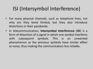
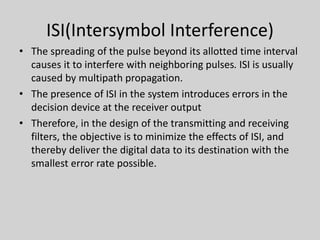
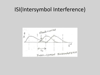
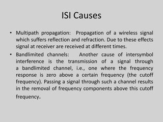
1. The document discusses intersymbol interference (ISI) and various techniques to mitigate its effects, including equalization. ISI occurs when symbols interfere with subsequent symbols due to issues like multipath propagation and bandlimited channels.
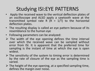
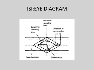
2. Eye patterns and diagrams can be used to study ISI and determine the optimal sampling time with the widest eye opening and least sensitivity to timing errors.
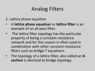
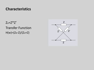
3. Equalization techniques aim to reverse channel distortions and make the frequency response flat. Analog techniques include Zobel networks and bridged-T filters, while digital techniques can use linear or decision feedback equalizers.
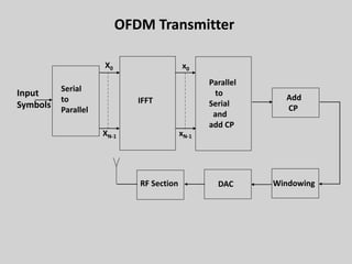
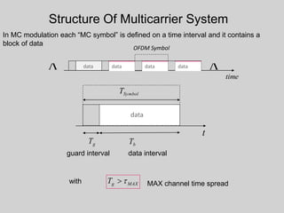
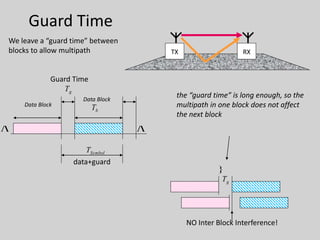
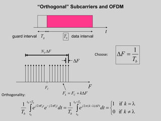
4. Orthogonal frequency-division multiplexing (OFDM) is introduced to combat ISI through dividing

![Digital Filters
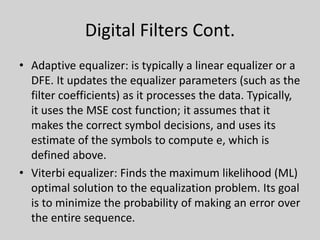
Equalizer types:
• Linear equalizer: processes the incoming signal with
a linear filter
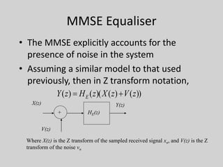
– MMSE equalizer: designs the filter to minimize
E[|e|], where e is the error signal, which is the
filter output minus the transmitted signal.
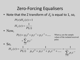
– Zero forcing equalizer: approximates the inverse of
the channel with a linear filter.
• Decision feedback equalizer: augments a linear
equalizer by adding a filtered version of previous
symbol estimates to the original filter output.](https://image.slidesharecdn.com/4095a8b4-bfef-4cfc-808f-d476d6c3a247-160707082433/85/frogcelsat-15-320.jpg)
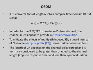
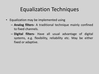
![OFDM - Cyclic Prefix (CP)
• OFDM signal with CP is x[n]L, and so y[n] = x[n] * h[n].
31](https://image.slidesharecdn.com/4095a8b4-bfef-4cfc-808f-d476d6c3a247-160707082433/85/frogcelsat-31-320.jpg)
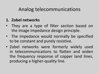
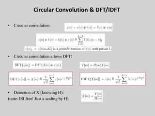
![• The received OFDM signal propagated through the channel h(n) is given by:
where w[n] is the additive white Gaussian noise and denotes the circular convolution.
CSNDSP 2008 32
][][][.][ nwnhnsnyr
](https://image.slidesharecdn.com/4095a8b4-bfef-4cfc-808f-d476d6c3a247-160707082433/85/frogcelsat-32-320.jpg)