Downloaded 355 times

![Equalization Techniques
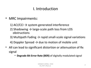
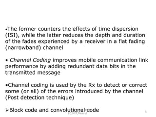
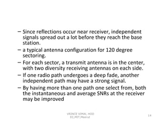
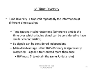
• The term equalization can be used to describe any signal
processing operation that minimizes ISI [2]
• Two operation modes for an adaptive equalizer: training
and tracking
•Three factors affect the time spanning over which an
equalizer converges: equalizer algorithm, equalizer
structure and time rate of change of the multipath radio
channel
•TDMA wireless systems are particularly well suited for
equalizers
VRINCE VIMAl, HOD
EC,MIT,Meerut
6](https://image.slidesharecdn.com/equalisationdiversitycoding-131224031432-phpapp01/85/Equalisation-diversity-coding-6-320.jpg)
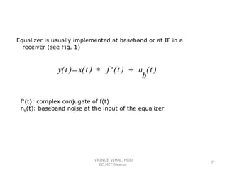
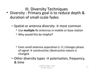
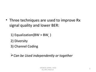
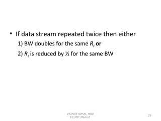
![• Spatial or Antenna Diversity → 4 basic types
M independent branches
Variable gain & phase at each branch → G∠ θ
Each branch has same average SNR:
Eb
SNR = Γ =
N0
γi
Instantaneous SNR = γ i, the pdf of
1
p (γ i ) = e
Γ
−γ i
Γ
γ i ≥ 0 (6.155)
is MSNR & the probability that any branch have I SNR less
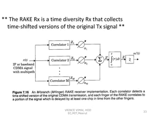
γ
γ
1
Pr [ γ i ≤ γ ] = ∫ p(γ i ) d γ i = ∫ e
Γ
0
0
−γ i
Γ
dγ i = 1 − e
−γ
Γ
15](https://image.slidesharecdn.com/equalisationdiversitycoding-131224031432-phpapp01/85/Equalisation-diversity-coding-15-320.jpg)
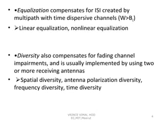
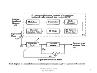
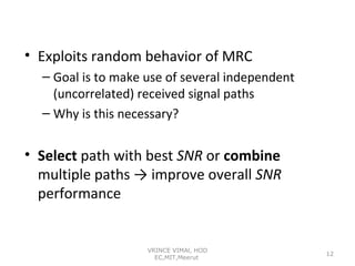
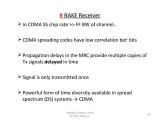
![ The probability that all M independent diversity branches Rx
signal which are simultaneously less than some specific SNR
threshold γ
Pr [ γ 1 ,...γ M ≤ γ ] = (1 − e −γ / Γ ) M = PM (γ )
Pr [ γ i > γ ] = 1 − PM (γ ) = 1 − (1 − e −γ / Γ ) M
The pdf of
γ
:
d
M
pM (γ ) =
PM (γ ) = ( 1 − e −γ
dγ
Γ
)
Γ M −1
e −γ
Γ
Average SNR improvement offered by selection diversity
∞
∞
0
0
γ = ∫ γ pM (γ )d γ = Γ ∫ Mx ( 1 − e − x )
M −1
e − x dx, x = γ Γ
M
γ
1
=∑
Γ k =1 k
16](https://image.slidesharecdn.com/equalisationdiversitycoding-131224031432-phpapp01/85/Equalisation-diversity-coding-16-320.jpg)
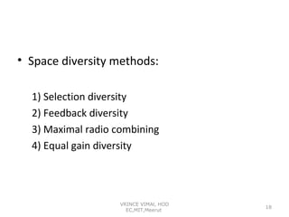
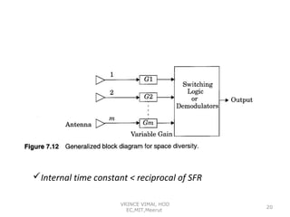
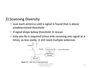

This document discusses various techniques used to improve mobile radio link performance including equalization, diversity, and channel coding. It describes equalization techniques that compensate for intersymbol interference caused by multipath. It explains different types of diversity including spatial, time, and frequency diversity that are used to mitigate fading. Specifically, it outlines four common spatial diversity techniques: selection diversity, maximal ratio combining, equal gain diversity, and scanning diversity. The document also discusses time diversity and RAKE receivers used in code division multiple access systems to exploit multipath for additional time diversity gain.


![[Year 2012-13] Mimo technology](https://cdn.slidesharecdn.com/ss_thumbnails/mimotechnology-180701101303-thumbnail.jpg?width=640&height=640&fit=bounds)


