This document provides an overview of digital communication system architecture and techniques for equalization. It discusses:
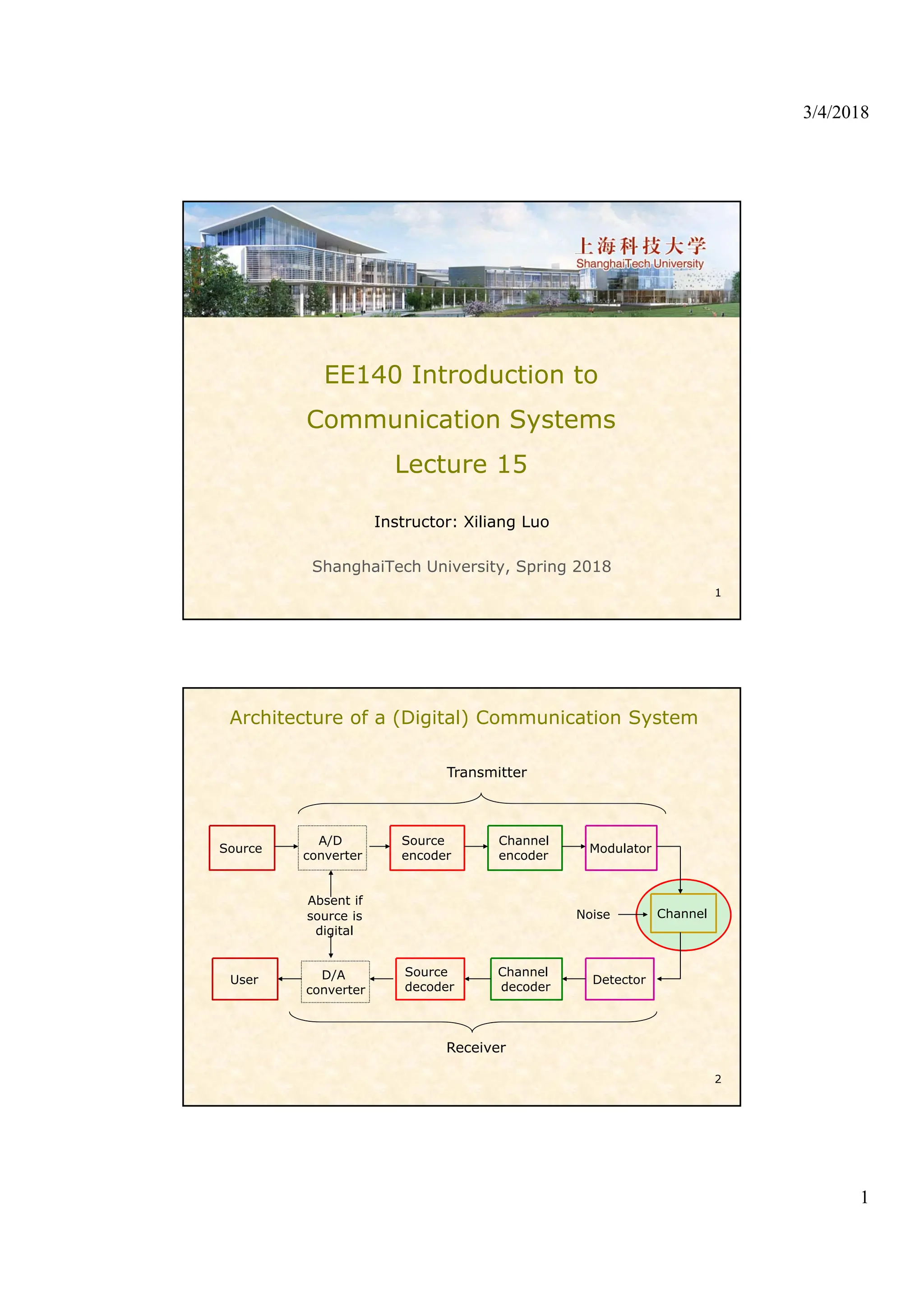
1) The basic components of a digital communication system including source encoding, channel encoding, modulation, and decoding.
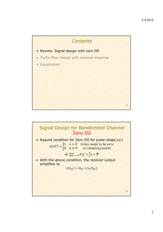
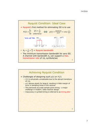
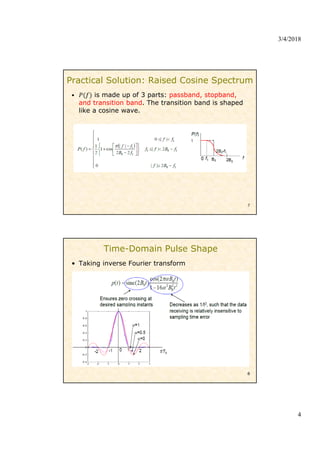
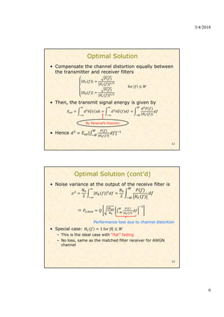
2) Methods for signal design to achieve zero inter-symbol interference (ISI) including the Nyquist criterion and raised cosine pulse shaping.
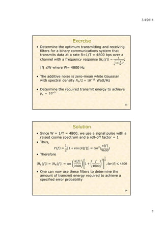
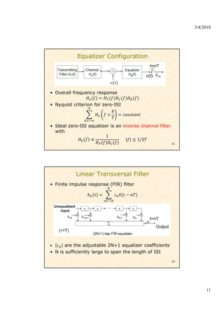
3) Transmit and receive filter design to compensate for the channel response and minimize noise and ISI.
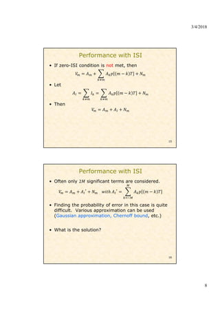
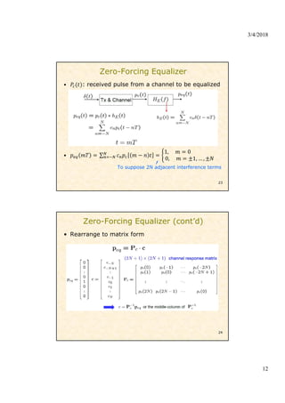
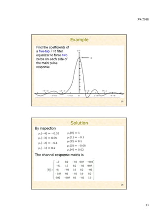
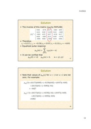
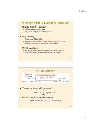
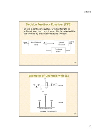
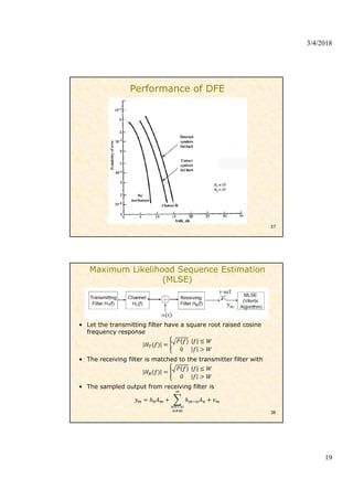
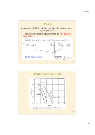
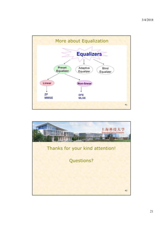
4) Equalization techniques used at the receiver including zero-forcing, minimum mean-square error (MMSE), decision feedback equalizers, and maximum likelihood sequence estimation to mitigate ISI caused by multipath channels.


![Multiband Transceivers - [Chapter 4] Design Parameters of Wireless Radios](https://cdn.slidesharecdn.com/ss_thumbnails/ch4-150613070934-lva1-app6892-thumbnail.jpg?width=640&height=640&fit=bounds)


