The document provides a detailed exploration of band-limited channels and the design of signals for effective transmission with minimal inter-symbol interference (ISI). It discusses various equalization techniques including linear, decision feedback, maximum likelihood sequence estimation (MLSE), turbo, and blind equalization methods, highlighting their principles, advantages, and challenges. Key concepts such as eye diagrams, Nyquist criteria, and the effects of channel characteristics on signal integrity are also examined.

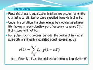
![CHARACTERISATION OF BAND LIMITED CHANNELS
Consider a band limited channel which is characterized as linear filter
with the low pass frequency response C(f) and the impulse response
as C(t).
Then a signal of the form
]
is transmitted over a bandpass telephone channel, the equivalent low
pass received signal is](https://image.slidesharecdn.com/remya-151108143357-lva1-app6892/85/pulse-shaping-and-equalization-7-320.jpg)
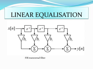
![LINEAR EQUALISATION
The linear equalizers are simple to implement and:
• Rely on the principle of inverting H (f ).
• Cancel ISI at the cost of possibly enhancing noise (ZFE), or provide
a tradeoff between noise enhancement and ISI removal (MMSE).
In non-blind mode, H (f ) is estimated by feeding an impulse.
Equalization is performed digitally, so h [n] is what usually matters.
In blind mode, the system uses known training sequences.
heq [n] is implemented as a FIR (finite impulse response) filter.](https://image.slidesharecdn.com/remya-151108143357-lva1-app6892/85/pulse-shaping-and-equalization-19-320.jpg)