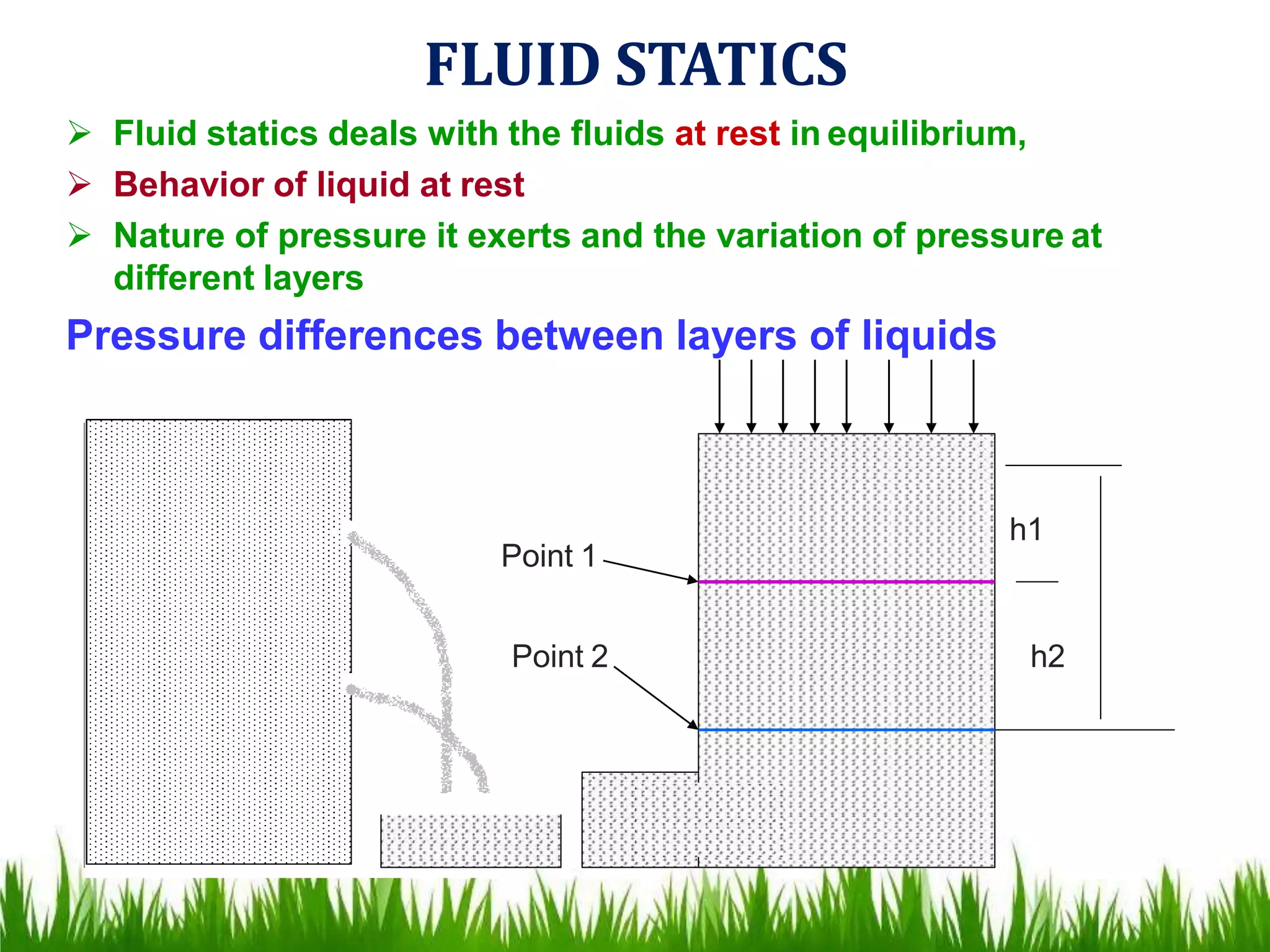
SlideShare a Scribd company logo
1 of 48
FLUID FLOW
V.JAGAN MOHAN RAO M.S.Pharm., MED.CHEM
NIPER-KOLKATA
Asst.Professor, MIPER-KURNOOL
EMAIL- jaganvana6@gmail.com
FLUID FLOW
A fluid is a substance that continually deforms (flows) under an
applied shear stress. Fluids are a subset of the phases of matter and
include liquids, gases both.
Fluid flow may be defined as the flow of substances that do not
permanently resist distortion.
The subject of fluid flow can be divided into fluid statics and fluid
dynamics.
Identification of type of flow is important in
Manufacture of dosage forms
Handling of drugs for administration
FLUID STATICS
 Fluid statics deals with the fluids at rest in equilibrium,
 Behavior of liquid at rest
 Nature of pressure it exerts and the variation of pressure at
different layers
Pressure differences between layers of liquids
h1
h2
Point 1
Point 2
Consider a column of liquid with two openings Which are
provided atthe wall of the vessel at different height
The rate of flow through these opening s are different due tothe
pressure exerted at the differentheight
Consider a stationary column the pressure ps is acting on the surface of
the fluid, column is maintained at constant pressure by applyingpressure
The force acting below and above the point 1 areevaluated
Substituting the force with pressure x area of cross section in theabove
equation
Force acting on the liquid
At point 1 =
Force on the surface
+ Force excreted by theliquid
Above point 1
Pressure at point 1 x Area =
Pressure on the surface x area
+ mass x acceleration
P1S = PsS + volume x density x acceleration
= PsS + height x area x density x acceleration
P1S = PsS + h1 S ρ g
Since surface area is same
P1 = Ps + h1 ρ g
Pressure acting on point 2 may be written as
P2 = Ps + h2 ρ g
Difference in the pressure is obtained by
P2 - P1 = g (Ps + h2 ρ ) – ( Ps + h1 ρ) g
∆P = (Ps + h2 ρ– Ps - h1 ρ ) g
= ∆ h ρ g
FLUID DYNAMICS
 Fluid dynamics deals with the study of fluids in
motion
 This knowledge is important for liquids, gels,
ointments which will change their flowbehavior
when exposed to different stress conditions
MIXING
FLOW THROUGHPIPES
FILLED IN CONTAINER
 The flow of fluid through a
closed channel can be
viscous or turbulent and it can
be observed by;
 Reynolds experiment
 Consider Glass tube which is
connected to reservoir of
water, rate of flow of water is
adjusted by a valve, a
reservoir of colored solution is
connected to one end of the
glass tube with help of nozzle
colored solution is introduced
into the nozzle as fine stream.
Laminar flow is one in which the fluid particles move in
layersor laminar with one layer sliding with other.
There is no exchange of fluid particles from one layer to
other.
When velocity of the water is increased the thread of the
colored water disappears and mass of the water gets
uniformly colored, indicates complete mixing of the solution
and the flow of the fluid is called as turbulent flow.
The velocity at which the fluid changes from laminar flow
to turbulent flow that velocity is called as critical velocity.
REYNOLDS NUMBER
 Inertial forces are due to mass and the velocity of the fluidparticles
trying to diffuse the fluid particles
 viscous force if the frictional force due to the viscosity of thefluid
which make the motion of the fluid in parallel
In Reynolds experiment the flow conditions are affectedby
Diameter ofpipe
Average velocity
Density of liquid
Viscosity of the fluid
This four factors are combined in one way as Reynolds number
Reynolds number is obtained by the following equation
D u ρ
η
INERTIALFORCES
= ------------------------------ =
VISCOUS FORCES
MASS X ACCELERATION OF LIQUIDFLOWING
---------------------------------------------------------
SHEAR STRESS XAREA
 If Re < 2000 the flow is said to be laminar
 If Re > 4000 the flow is said to be turbulent
 If Re lies between 2000 to 4000 the flow change between
laminar to turbulent
 APPLICATIONS
 Reynolds number is used to predict the nature of theflow
 Stocks law equation is modified to include Reynolds number to study
the rate of sedimentation in suspension
BERNOULLI'S THEOREM
When the principals of the law of conservation energy is applied tothe
flow of the fluids the resulting equation is called Bernoulli's theorem
 Consider a pump working under isothermal conditions between pointsA
and B as shown in figure;
13
 At point a one kilogram of liquid is assumed to be entering atthis
point, pressure energy at joule can be writtenas
Pressure energy = Pa /g ρ A
Where Pa = Pressure at point a
g = Acceleration due togravity
ρ A = Density of theliquid
Potential energy of a body is defined as the energy possessedby
the body by the virtue of its position or configuration
Potential energy = XA
Kinetic energy of a body is defined as the energy possessed by the
body by virtue of its motion,
kinetic energy = UA / 2g2
Total energy at point A = Pressure energy + Potential energy+Kinetic
energy
Total energy at point A = Pa /g ρ A +XA + UA / 2g2
According to the Bernoulli's theorem the total energy atpoint
A is constant
Total energy at point A = Pa /g ρ A +XA + UA / 2g = Constant2
After the system reaches the steady state, whenever one kilogramof
liquid enters at point A, another one kilogram of liquid leaves at point B
Total energy at point B = PB /g ρ B +XB + UB / 2g2
INPOUT = OUT PUT
Pa /g ρ A +XA + U 2 / 2g =PB /g ρ B +XB + U 2 / 2g
A B
Theoretically all kids of the energies involved in fluid flow should be
accounted, pump has added certain amount ofenergy
Energy added by the pump = + wJ
• This equation is called as Bernoulli's
equation
• Application
 Used in the measurement of rate of fluidflow
 It applied in the working of the centrifugal pump, in this kinetic energyis
converted in to pressure
During the transport some energy is converted to heat due tofrictional Forces
Loss of energy due to friction in the line =FJ
ENERGY LOSS
 According to the law of conversation of energy ,energy balance
have to be properly calculated
 fluids experiences energy losses in several ways while
flowing through pipes, they are
 Frictional losses
 Losses in the fitting
 Enlargement losses
 Contraction losses
FRICTIONAL LOSSES
During flow of fluids frictional forces causes a loss in pressure Type of
fluid flow also influences the losses
In general pressure drop will be
PRESSURE DROP α VELOCITY (u)
α Density of fluid(ρ)
α Length of the pipe (L)
α 1 / diameter of the pipe (D)
These relationships are proposed in Fanning equation for calculating
friction losses
Fanning equation ∆p = 2fu2Lρ / D
F = frictional factor
For viscous flow pressure drop Hagen –Poiseullie equation
= 32 Luη / D2
LOSSES IN FITTING
Fanning equation is applicable for the losses in straight pipe When
fitting are introduced into a straight pipe, They cause disturbance in the
flow, Which result in the additional loss of energy
losses in fitting may be due to
Change in direction
Change in the type of fittings
Equivalent length of fitting = Equivalent length x internal diameter
For globe valve = 300 x 50
= 15 meter
That means globe valve is equal to 15 meters straight line, so this
length is substituted in fanning equation
Tee fitting
Equivalent length = 90
Globe valve equivalent length = 300
ENLARGEMENT LOSS
If the cross section of the pipe enlarges gradually, the fluid adaptsitself
to the changed section with out any disturbance So no loss of energy
If the cross section of the pipe changes suddenly then loss in energy is
observed due to eddies These are greater at this point than straight line
pipe
Than u2< u1
For sudden enlargement = ∆ H = (u1 –u2 )2 / 2g
∆ H = loss of head due to sudden enlargement
µ1 µ2
µ1
µ2
CONTRACTION LOSSES
If the cross section of the pipe is reduced suddenly the fluid flow is
disturbed, the diameter of the fluid stream is less than the initial value of
diameter this point of minimum cross section is known as vena
contracta.
the velocity of fluid at smaller cross section will be greater than at larger
cross section, u2> u1
MANOMETERS
Manometers are the devices used for measuring the pressure
difference Different type of manometers are;
1) Simple manometer
2) Differential manometer
3) Inclined manometer
SIMPLE MANOMETER
 This manometer is the most commonly used one
 It consists of a glass U shaped tube filled with a liquid A- of
density ρA kg /meter cube and above A the arms are filled with liquid B
of density ρB .
 The liquid A and B are immiscible and the interference can be seen
clearly
 If two different pressures are applied on the two arms the meniscusof
the one liquid will be higher than the other
 Let pressure at point 1 will be P1 Pascal's and point 5 will be P2
Pascal's
 The pressure at point 2 can be written as
= P1+ (m + R ) ρ B g
(m + R ) = distance from 3 to 5
P1 P2
m
R
1
2
3
4
5
LiquidA
LIQUIDB
Since the points 2 and 3 are at same height the pressure
at 3 can be written as
Pressure at 3 =P1+ (m + R ) ρ Bg
Pressure at 4 can be written as
= P2 + gm ρB
or
= P1+ ρ B ( m + R ) g- ρ a R g
Both the equations should be equal
P2 + gm ρ B = P1+ ρ B ( m + R ) g- ρ a R g
P1 – P2 = gm ρ B - ρ B ( m + R) g + ρ A R g
∆P = gm ρ B - gm ρ B - R ρ B g + R ρ A
=R (ρ A- ρ B )g
DIFFERENTIAL MANOMETERS
 These manometers are suitable for measurement of small
pressure differences
 It is also known as two – Fluid U- tube manometer
 It contains two immiscible liquids A and B having nearly same
densities
 The U tube contains of enlarged chambers on both limbs,
 Using the principle of simple manometer the pressure
differences canbe written as
∆P =P1 –P2 =R (ρc – ρA)g
INCLINED TUBE MANOMETERS
Many applications require accurate measurement of low
pressure suchas drafts and very low differentials, primarily in air
and gasinstallations
In these applications the manometer is arranged with the
indicatingtube inclined, as in Figure, therefore providing an
expanded scale
This enables the measurement of small pressure changes with
increased
accuracy
P1 –P2 = g R (ρ A - ρ B) sin α
MEASUREMENT OF RATE OF FLOW OF FLUIDS
When ever fluid are used in a process it is necessary to measurethe
rate at which the fluid is flowing through the pipe,
Methods of measurement are
Direct weighing or measuring
Hydrodynamic methods
Orifice meter
Venturi meter
Pitot meter
Rotameter
Direct displacement meter
The liquid flowing through a pipe is collected for specific period
at any point and weighed or measured, and the rate of flow canbe determined.
Gases can not be determined by thismethod.
ORIFICE METER
Principle:
Orifice meter is a thin plate containing a narrow and sharpaperture
When a fluid stream is allowed to pass through a narrow constrictionthe
velocity of the fluid increase compared to upstream
This results in decrease in pressure drop and the difference inthe
pressure may be read from amanometer
The velocity of the fluid at thin constriction may be writtenas
U0 =C 0 √ 2g∆H
DIRECT WEIGHING OR MEASURING
∆H = difference in height, can be measured by manometer C0
=constant
U0 = velocity of fluid at the point of orificemeter
CONSTRUCTION
 It is consider to be a thin plate containing a sharp aperturethrough
which fluid flows
 Normally it is placed between long straightpipes
 For present discussion plate is introduced into pipe and manometeris
connected at points A and B
WORKING
 Orifice meter is referred as the variable head meter, ie it measure the
variation in the pressure across a fixed construction placed in thepath
of flow
 When fluid is allowed to pass through the orifice the velocity of the fluid
at point B increase, as a result at point A pressure will be increased
 Difference in the pressure is measured by manometer
 Bernoulli's equation is applied to point A and point B for experimental
conditions
õ0
2 –µ 2 =C √2g ∆H
A 0
µ0 = velocity of fluid atorifice
µA = velocity of fluid at point A
C0 = constant
 If the diameter of the orifice is 1/5 or less of the pipe diameter thenµA
µ0 = C0 √2g ∆His neglected so,
Applications
 Velocity at either of the point A and B can be measured
 Volume of liquid flowing per hour can be determined
VENTURI METER
• Principle:
 Venturi meter consist of two tapered sections in the
pipe line with a gradual constriction at its centre.
 When fluid stream is allowed to pass through the
narrow throat the velocity of the fluid increases at
the venturi compared to velocity of the upstream.
 This results in decrease in the pressure head.
 This resulting decrease in the pressure head is
measured directly from the manometer.
38
Disadvantages
 Expensive
 Need technical expert
 Not flexible
 Occupies more space
Advantages
 Power loss is less
 Head loss is negligible
Applications:
 It is commonly used for liquids, specially for water.
 It can also be used for the measurement of gases.
PITOT TUBE
• Principle:
 Pitot tube consists of sensing element with a small
constriction compared to the size of the flow
channel.
 When the sensing element is inserted at the center
of the stream, the velocity of flow is increased.
 This results in decrease in pressure head.
∆Hp = u2 /2g
PITOT TUBE
Construction
 It is also known as insertion meter or insertion tube
 The size of the sensing element is small compared to theflow channel
 The point of measurement may be at the center of thechannel
 One tube is perpendicular to the flow direction and the otheris
parallel to the flow
 Two tubes are connected to themanometer
Working
 Tube are inserted in the flow shown is the figure.
 Pitot tube is used to measure the velocity head of the flow.
 In this tube velocity of fluid is increased at the narrow
constriction which results in decreased pressure.
 Tube at right angles to the flow measures
pressure head only while the tube that points
upstream measures pressure head and velocity
head.
µ2= Cv √2g ∆H
 Cv coefficient of Pitot tube
ROTAMETER
Principle:
 Rotameter is known as area meter as it measures area of
flow.
 It consist of a vertical, tapered and transparent tube in
which plummet is placed.
 During the fluid flow through the tube the plummet rises
and falls because of variation of flow.
Construction
 It consists of vertically tapered and transparent tube with narrow end
down, in which a plummet is placed.
 A solid plummet is placed in the tube. The diameter of the plummet is
smaller than the narrowest part of the tube.
 Floats/plummet is made up of glass, aluminium or plastic.
 The tube is usually made of glass on which linear scale is given.
 During the flow the plummet rise due to variation in flow
 The upper edge of the plummet is used as an index to note the reading
47
flow of fluids

More Related Content

What's hot

Pharmaceutical Engineering Unit- 1 Chapter -1 Flow of fluid.pptx
Pharmaceutical Engineering Unit- 1 Chapter -1 Flow of fluid.pptxPharmaceutical Engineering Unit- 1 Chapter -1 Flow of fluid.pptx
Pharmaceutical Engineering Unit- 1 Chapter -1 Flow of fluid.pptxNikita Gupta
 
Pharmaceutical Engineering Unit -3.pptx
Pharmaceutical Engineering Unit -3.pptxPharmaceutical Engineering Unit -3.pptx
Pharmaceutical Engineering Unit -3.pptxNikita Gupta
 
Pharmaceutical Engineering: Filtration
Pharmaceutical Engineering: Filtration Pharmaceutical Engineering: Filtration
Pharmaceutical Engineering: Filtration Parag Jain
 
Heat transfer By Ankita Yagnik
Heat transfer By Ankita YagnikHeat transfer By Ankita Yagnik
Heat transfer By Ankita YagnikAnkita Yagnik
 
Pharmaceutical Engineering: Size reduction
Pharmaceutical Engineering: Size reductionPharmaceutical Engineering: Size reduction
Pharmaceutical Engineering: Size reductionParag Jain
 
Pharmaceutical engineering: Heat transfer
Pharmaceutical engineering: Heat transferPharmaceutical engineering: Heat transfer
Pharmaceutical engineering: Heat transferParag Jain
 
Climbing film evaporator || Pharmaceutical Engineering || Anurag Gupta
Climbing film evaporator || Pharmaceutical Engineering || Anurag GuptaClimbing film evaporator || Pharmaceutical Engineering || Anurag Gupta
Climbing film evaporator || Pharmaceutical Engineering || Anurag GuptaAnurag Gupta
 
Solid-Crystalline, Amorphous & Polymorphism
Solid-Crystalline, Amorphous  & PolymorphismSolid-Crystalline, Amorphous  & Polymorphism
Solid-Crystalline, Amorphous & PolymorphismSuyash Jain
 
Surface and Interfacial tension [Part-3(a)] (Measurement of Surface and Inter...
Surface and Interfacial tension [Part-3(a)](Measurement of Surface and Inter...Surface and Interfacial tension [Part-3(a)](Measurement of Surface and Inter...
Surface and Interfacial tension [Part-3(a)] (Measurement of Surface and Inter...Ms. Pooja Bhandare
 
Evaporation - Pharmaceutical Engineering 1st
Evaporation - Pharmaceutical Engineering 1stEvaporation - Pharmaceutical Engineering 1st
Evaporation - Pharmaceutical Engineering 1stRAHUL PAL
 
Pharmaceutical Engineering: Drying
Pharmaceutical Engineering: DryingPharmaceutical Engineering: Drying
Pharmaceutical Engineering: DryingParag Jain
 
State of matter and properties of matter (Part-6)(Relative humidity, Liquid ...
State of matter and properties  of matter (Part-6)(Relative humidity, Liquid ...State of matter and properties  of matter (Part-6)(Relative humidity, Liquid ...
State of matter and properties of matter (Part-6)(Relative humidity, Liquid ...Ms. Pooja Bhandare
 
Pharmaceutical Engineering Unit -2.pptx
Pharmaceutical Engineering Unit -2.pptxPharmaceutical Engineering Unit -2.pptx
Pharmaceutical Engineering Unit -2.pptxNikita Gupta
 
Drying by Ankita Yagnik
Drying by Ankita YagnikDrying by Ankita Yagnik
Drying by Ankita YagnikAnkita Yagnik
 
States of matter and properties of matter
States of matter and properties of matterStates of matter and properties of matter
States of matter and properties of matterJILSHA123
 
Physical Pharmaceutics-I Unit-III Surface and Interfacial tension (Part-1)(Li...
Physical Pharmaceutics-IUnit-IIISurface and Interfacial tension (Part-1)(Li...Physical Pharmaceutics-IUnit-IIISurface and Interfacial tension (Part-1)(Li...
Physical Pharmaceutics-I Unit-III Surface and Interfacial tension (Part-1)(Li...Ms. Pooja Bhandare
 

What's hot (20)

Pharmaceutical Engineering Unit- 1 Chapter -1 Flow of fluid.pptx
Pharmaceutical Engineering Unit- 1 Chapter -1 Flow of fluid.pptxPharmaceutical Engineering Unit- 1 Chapter -1 Flow of fluid.pptx
Pharmaceutical Engineering Unit- 1 Chapter -1 Flow of fluid.pptx
 
Pharmaceutical Engineering Unit -3.pptx
Pharmaceutical Engineering Unit -3.pptxPharmaceutical Engineering Unit -3.pptx
Pharmaceutical Engineering Unit -3.pptx
 
Pharmaceutical Engineering: Filtration
Pharmaceutical Engineering: Filtration Pharmaceutical Engineering: Filtration
Pharmaceutical Engineering: Filtration
 
Heat transfer By Ankita Yagnik
Heat transfer By Ankita YagnikHeat transfer By Ankita Yagnik
Heat transfer By Ankita Yagnik
 
B.Pharm, Sem 3 size separation
B.Pharm, Sem 3 size separationB.Pharm, Sem 3 size separation
B.Pharm, Sem 3 size separation
 
Pharmaceutical Engineering: Size reduction
Pharmaceutical Engineering: Size reductionPharmaceutical Engineering: Size reduction
Pharmaceutical Engineering: Size reduction
 
Pharmaceutical engineering: Heat transfer
Pharmaceutical engineering: Heat transferPharmaceutical engineering: Heat transfer
Pharmaceutical engineering: Heat transfer
 
Climbing film evaporator || Pharmaceutical Engineering || Anurag Gupta
Climbing film evaporator || Pharmaceutical Engineering || Anurag GuptaClimbing film evaporator || Pharmaceutical Engineering || Anurag Gupta
Climbing film evaporator || Pharmaceutical Engineering || Anurag Gupta
 
Solid-Crystalline, Amorphous & Polymorphism
Solid-Crystalline, Amorphous  & PolymorphismSolid-Crystalline, Amorphous  & Polymorphism
Solid-Crystalline, Amorphous & Polymorphism
 
Surface and Interfacial tension [Part-3(a)] (Measurement of Surface and Inter...
Surface and Interfacial tension [Part-3(a)](Measurement of Surface and Inter...Surface and Interfacial tension [Part-3(a)](Measurement of Surface and Inter...
Surface and Interfacial tension [Part-3(a)] (Measurement of Surface and Inter...
 
Evaporation - Pharmaceutical Engineering 1st
Evaporation - Pharmaceutical Engineering 1stEvaporation - Pharmaceutical Engineering 1st
Evaporation - Pharmaceutical Engineering 1st
 
Spreading coefficient
Spreading coefficientSpreading coefficient
Spreading coefficient
 
Pharmaceutical Engineering: Drying
Pharmaceutical Engineering: DryingPharmaceutical Engineering: Drying
Pharmaceutical Engineering: Drying
 
State of matter and properties of matter (Part-6)(Relative humidity, Liquid ...
State of matter and properties  of matter (Part-6)(Relative humidity, Liquid ...State of matter and properties  of matter (Part-6)(Relative humidity, Liquid ...
State of matter and properties of matter (Part-6)(Relative humidity, Liquid ...
 
Pharmaceutical Engineering Unit -2.pptx
Pharmaceutical Engineering Unit -2.pptxPharmaceutical Engineering Unit -2.pptx
Pharmaceutical Engineering Unit -2.pptx
 
Orifice Meter
Orifice Meter Orifice Meter
Orifice Meter
 
Drying by Ankita Yagnik
Drying by Ankita YagnikDrying by Ankita Yagnik
Drying by Ankita Yagnik
 
States of matter and properties of matter
States of matter and properties of matterStates of matter and properties of matter
States of matter and properties of matter
 
Physical Pharmaceutics-I Unit-III Surface and Interfacial tension (Part-1)(Li...
Physical Pharmaceutics-IUnit-IIISurface and Interfacial tension (Part-1)(Li...Physical Pharmaceutics-IUnit-IIISurface and Interfacial tension (Part-1)(Li...
Physical Pharmaceutics-I Unit-III Surface and Interfacial tension (Part-1)(Li...
 
Drying
DryingDrying
Drying
 

Similar to flow of fluids

Fluid flow 2.pdf
Fluid flow 2.pdfFluid flow 2.pdf
Fluid flow 2.pdfsafuraqazi
 
Flow of Fluids.ppt
Flow of Fluids.pptFlow of Fluids.ppt
Flow of Fluids.pptPoonam Patil
 
Fluidflowsb-160915165853 (1).pdf
Fluidflowsb-160915165853 (1).pdfFluidflowsb-160915165853 (1).pdf
Fluidflowsb-160915165853 (1).pdfSaqibShaik2
 
flow of fluid and its mechanism along with principle
flow of fluid and its mechanism along with principleflow of fluid and its mechanism along with principle
flow of fluid and its mechanism along with principleAkankshaPatel55
 
Unit I Flow of fluids-WPS Office.pdf
Unit I Flow of fluids-WPS Office.pdfUnit I Flow of fluids-WPS Office.pdf
Unit I Flow of fluids-WPS Office.pdfSudipta Roy
 
PCE-Lecture-2-4-FluidMechanics.pdf chemical engg
PCE-Lecture-2-4-FluidMechanics.pdf chemical enggPCE-Lecture-2-4-FluidMechanics.pdf chemical engg
PCE-Lecture-2-4-FluidMechanics.pdf chemical enggPandiaRajan52
 
Me 2204 fluid mechanics and machinery
Me 2204 fluid mechanics and machineryMe 2204 fluid mechanics and machinery
Me 2204 fluid mechanics and machineryanish antony
 
Fluid mechanics-ppt
Fluid mechanics-pptFluid mechanics-ppt
Fluid mechanics-pptAnil Rout
 
MECHANICAL_PROPERTIES_OF_FLUIDS.ppt
MECHANICAL_PROPERTIES_OF_FLUIDS.pptMECHANICAL_PROPERTIES_OF_FLUIDS.ppt
MECHANICAL_PROPERTIES_OF_FLUIDS.pptAryan979811
 
Open Channel VS Pipe Flow
Open Channel VS Pipe FlowOpen Channel VS Pipe Flow
Open Channel VS Pipe FlowFatma Abdalla
 
Fluid Mechanics Chapter 2. Fluid Statics
Fluid Mechanics Chapter 2. Fluid StaticsFluid Mechanics Chapter 2. Fluid Statics
Fluid Mechanics Chapter 2. Fluid StaticsAddisu Dagne Zegeye
 
Lecture 3 bernoulli_s_theorm_it_s_applications
Lecture 3 bernoulli_s_theorm_it_s_applicationsLecture 3 bernoulli_s_theorm_it_s_applications
Lecture 3 bernoulli_s_theorm_it_s_applicationsRaghubir Singh
 
9-Viscous flow in ducts.pptx
9-Viscous flow in ducts.pptx9-Viscous flow in ducts.pptx
9-Viscous flow in ducts.pptxDaniel678511
 

Similar to flow of fluids (20)

Fluid flow 2.pdf
Fluid flow 2.pdfFluid flow 2.pdf
Fluid flow 2.pdf
 
Flow of Fluids.ppt
Flow of Fluids.pptFlow of Fluids.ppt
Flow of Fluids.ppt
 
Fluidflowsb-160915165853 (1).pdf
Fluidflowsb-160915165853 (1).pdfFluidflowsb-160915165853 (1).pdf
Fluidflowsb-160915165853 (1).pdf
 
flow of fluid and its mechanism along with principle
flow of fluid and its mechanism along with principleflow of fluid and its mechanism along with principle
flow of fluid and its mechanism along with principle
 
fluid flow.pdf
fluid flow.pdffluid flow.pdf
fluid flow.pdf
 
Fluid flow
Fluid flowFluid flow
Fluid flow
 
Unit I Flow of fluids-WPS Office.pdf
Unit I Flow of fluids-WPS Office.pdfUnit I Flow of fluids-WPS Office.pdf
Unit I Flow of fluids-WPS Office.pdf
 
PCE-Lecture-2-4-FluidMechanics.pdf chemical engg
PCE-Lecture-2-4-FluidMechanics.pdf chemical enggPCE-Lecture-2-4-FluidMechanics.pdf chemical engg
PCE-Lecture-2-4-FluidMechanics.pdf chemical engg
 
Me 2204 fluid mechanics and machinery
Me 2204 fluid mechanics and machineryMe 2204 fluid mechanics and machinery
Me 2204 fluid mechanics and machinery
 
FLUID MECHANICS AND HYDRAULIC MACHINES
FLUID MECHANICS AND HYDRAULIC MACHINES FLUID MECHANICS AND HYDRAULIC MACHINES
FLUID MECHANICS AND HYDRAULIC MACHINES
 
Fluid mechanics-ppt
Fluid mechanics-pptFluid mechanics-ppt
Fluid mechanics-ppt
 
MECHANICAL_PROPERTIES_OF_FLUIDS.ppt
MECHANICAL_PROPERTIES_OF_FLUIDS.pptMECHANICAL_PROPERTIES_OF_FLUIDS.ppt
MECHANICAL_PROPERTIES_OF_FLUIDS.ppt
 
fluid statics
fluid staticsfluid statics
fluid statics
 
Open Channel VS Pipe Flow
Open Channel VS Pipe FlowOpen Channel VS Pipe Flow
Open Channel VS Pipe Flow
 
Fluid mechanics basics
Fluid mechanics basicsFluid mechanics basics
Fluid mechanics basics
 
Fluid mechanics-2014-2b4j5bo
Fluid mechanics-2014-2b4j5boFluid mechanics-2014-2b4j5bo
Fluid mechanics-2014-2b4j5bo
 
Fluid Mechanics Chapter 2. Fluid Statics
Fluid Mechanics Chapter 2. Fluid StaticsFluid Mechanics Chapter 2. Fluid Statics
Fluid Mechanics Chapter 2. Fluid Statics
 
Lecture 3 bernoulli_s_theorm_it_s_applications
Lecture 3 bernoulli_s_theorm_it_s_applicationsLecture 3 bernoulli_s_theorm_it_s_applications
Lecture 3 bernoulli_s_theorm_it_s_applications
 
Flow of fluids
Flow of fluidsFlow of fluids
Flow of fluids
 
9-Viscous flow in ducts.pptx
9-Viscous flow in ducts.pptx9-Viscous flow in ducts.pptx
9-Viscous flow in ducts.pptx
 

More from jagan vana

Pathophysiology of Asthma
Pathophysiology of AsthmaPathophysiology of Asthma
Pathophysiology of Asthmajagan vana
 
11. materialsof construction
11. materialsof construction11. materialsof construction
11. materialsof constructionjagan vana
 
centrifugation
centrifugationcentrifugation
centrifugationjagan vana
 
size seperation
size seperationsize seperation
size seperationjagan vana
 
size reduction
size reductionsize reduction
size reductionjagan vana
 
Transplantation and tissue rejection
Transplantation and tissue rejectionTransplantation and tissue rejection
Transplantation and tissue rejectionjagan vana
 
Organ function tests
Organ function testsOrgan function tests
Organ function testsjagan vana
 
Neoplastic diseases
Neoplastic diseasesNeoplastic diseases
Neoplastic diseasesjagan vana
 
Inflammatory bowel diseases
Inflammatory bowel diseasesInflammatory bowel diseases
Inflammatory bowel diseasesjagan vana
 
Inflammation and repair
Inflammation and repairInflammation and repair
Inflammation and repairjagan vana
 

More from jagan vana (20)

Haemophilia
HaemophiliaHaemophilia
Haemophilia
 
Gonorrhoea
GonorrhoeaGonorrhoea
Gonorrhoea
 
Pathophysiology of Asthma
Pathophysiology of AsthmaPathophysiology of Asthma
Pathophysiology of Asthma
 
corrosion
corrosioncorrosion
corrosion
 
11. materialsof construction
11. materialsof construction11. materialsof construction
11. materialsof construction
 
centrifugation
centrifugationcentrifugation
centrifugation
 
filtration
filtrationfiltration
filtration
 
mixing
mixingmixing
mixing
 
drying
dryingdrying
drying
 
distillation
distillationdistillation
distillation
 
evaporation
evaporationevaporation
evaporation
 
heat transfer
heat transferheat transfer
heat transfer
 
size seperation
size seperationsize seperation
size seperation
 
size reduction
size reductionsize reduction
size reduction
 
Transplantation and tissue rejection
Transplantation and tissue rejectionTransplantation and tissue rejection
Transplantation and tissue rejection
 
Organ function tests
Organ function testsOrgan function tests
Organ function tests
 
Neoplastic diseases
Neoplastic diseasesNeoplastic diseases
Neoplastic diseases
 
Leprosy
LeprosyLeprosy
Leprosy
 
Inflammatory bowel diseases
Inflammatory bowel diseasesInflammatory bowel diseases
Inflammatory bowel diseases
 
Inflammation and repair
Inflammation and repairInflammation and repair
Inflammation and repair
 

Recently uploaded

Contemporary philippine arts from the regions_PPT_Module_12 [Autosaved] (1).pptx
Contemporary philippine arts from the regions_PPT_Module_12 [Autosaved] (1).pptxContemporary philippine arts from the regions_PPT_Module_12 [Autosaved] (1).pptx
Contemporary philippine arts from the regions_PPT_Module_12 [Autosaved] (1).pptxRoyAbrique
 
Hybridoma Technology ( Production , Purification , and Application )
Hybridoma Technology  ( Production , Purification , and Application  ) Hybridoma Technology  ( Production , Purification , and Application  )
Hybridoma Technology ( Production , Purification , and Application ) Sakshi Ghasle
 
Introduction to AI in Higher Education_draft.pptx
Introduction to AI in Higher Education_draft.pptxIntroduction to AI in Higher Education_draft.pptx
Introduction to AI in Higher Education_draft.pptxpboyjonauth
 
Interactive Powerpoint_How to Master effective communication
Interactive Powerpoint_How to Master effective communicationInteractive Powerpoint_How to Master effective communication
Interactive Powerpoint_How to Master effective communicationnomboosow
 
Accessible design: Minimum effort, maximum impact
Accessible design: Minimum effort, maximum impactAccessible design: Minimum effort, maximum impact
Accessible design: Minimum effort, maximum impactdawncurless
 
POINT- BIOCHEMISTRY SEM 2 ENZYMES UNIT 5.pptx
POINT- BIOCHEMISTRY SEM 2 ENZYMES UNIT 5.pptxPOINT- BIOCHEMISTRY SEM 2 ENZYMES UNIT 5.pptx
POINT- BIOCHEMISTRY SEM 2 ENZYMES UNIT 5.pptxSayali Powar
 
Presiding Officer Training module 2024 lok sabha elections
Presiding Officer Training module 2024 lok sabha electionsPresiding Officer Training module 2024 lok sabha elections
Presiding Officer Training module 2024 lok sabha electionsanshu789521
 
BASLIQ CURRENT LOOKBOOK LOOKBOOK(1) (1).pdf
BASLIQ CURRENT LOOKBOOK  LOOKBOOK(1) (1).pdfBASLIQ CURRENT LOOKBOOK  LOOKBOOK(1) (1).pdf
BASLIQ CURRENT LOOKBOOK LOOKBOOK(1) (1).pdfSoniaTolstoy
 
Introduction to ArtificiaI Intelligence in Higher Education
Introduction to ArtificiaI Intelligence in Higher EducationIntroduction to ArtificiaI Intelligence in Higher Education
Introduction to ArtificiaI Intelligence in Higher Educationpboyjonauth
 
MENTAL STATUS EXAMINATION format.docx
MENTAL     STATUS EXAMINATION format.docxMENTAL     STATUS EXAMINATION format.docx
MENTAL STATUS EXAMINATION format.docxPoojaSen20
 
Organic Name Reactions for the students and aspirants of Chemistry12th.pptx
Organic Name Reactions  for the students and aspirants of Chemistry12th.pptxOrganic Name Reactions  for the students and aspirants of Chemistry12th.pptx
Organic Name Reactions for the students and aspirants of Chemistry12th.pptxVS Mahajan Coaching Centre
 
A Critique of the Proposed National Education Policy Reform
A Critique of the Proposed National Education Policy ReformA Critique of the Proposed National Education Policy Reform
A Critique of the Proposed National Education Policy ReformChameera Dedduwage
 
_Math 4-Q4 Week 5.pptx Steps in Collecting Data
_Math 4-Q4 Week 5.pptx Steps in Collecting Data_Math 4-Q4 Week 5.pptx Steps in Collecting Data
_Math 4-Q4 Week 5.pptx Steps in Collecting DataJhengPantaleon
 
Science 7 - LAND and SEA BREEZE and its Characteristics
Science 7 - LAND and SEA BREEZE and its CharacteristicsScience 7 - LAND and SEA BREEZE and its Characteristics
Science 7 - LAND and SEA BREEZE and its CharacteristicsKarinaGenton
 
Class 11 Legal Studies Ch-1 Concept of State .pdf
Class 11 Legal Studies Ch-1 Concept of State .pdfClass 11 Legal Studies Ch-1 Concept of State .pdf
Class 11 Legal Studies Ch-1 Concept of State .pdfakmcokerachita
 
How to Make a Pirate ship Primary Education.pptx
How to Make a Pirate ship Primary Education.pptxHow to Make a Pirate ship Primary Education.pptx
How to Make a Pirate ship Primary Education.pptxmanuelaromero2013
 
CARE OF CHILD IN INCUBATOR..........pptx
CARE OF CHILD IN INCUBATOR..........pptxCARE OF CHILD IN INCUBATOR..........pptx
CARE OF CHILD IN INCUBATOR..........pptxGaneshChakor2
 

Recently uploaded (20)

Contemporary philippine arts from the regions_PPT_Module_12 [Autosaved] (1).pptx
Contemporary philippine arts from the regions_PPT_Module_12 [Autosaved] (1).pptxContemporary philippine arts from the regions_PPT_Module_12 [Autosaved] (1).pptx
Contemporary philippine arts from the regions_PPT_Module_12 [Autosaved] (1).pptx
 
Hybridoma Technology ( Production , Purification , and Application )
Hybridoma Technology  ( Production , Purification , and Application  ) Hybridoma Technology  ( Production , Purification , and Application  )
Hybridoma Technology ( Production , Purification , and Application )
 
Introduction to AI in Higher Education_draft.pptx
Introduction to AI in Higher Education_draft.pptxIntroduction to AI in Higher Education_draft.pptx
Introduction to AI in Higher Education_draft.pptx
 
Interactive Powerpoint_How to Master effective communication
Interactive Powerpoint_How to Master effective communicationInteractive Powerpoint_How to Master effective communication
Interactive Powerpoint_How to Master effective communication
 
Accessible design: Minimum effort, maximum impact
Accessible design: Minimum effort, maximum impactAccessible design: Minimum effort, maximum impact
Accessible design: Minimum effort, maximum impact
 
Model Call Girl in Bikash Puri Delhi reach out to us at 🔝9953056974🔝
Model Call Girl in Bikash Puri  Delhi reach out to us at 🔝9953056974🔝Model Call Girl in Bikash Puri  Delhi reach out to us at 🔝9953056974🔝
Model Call Girl in Bikash Puri Delhi reach out to us at 🔝9953056974🔝
 
POINT- BIOCHEMISTRY SEM 2 ENZYMES UNIT 5.pptx
POINT- BIOCHEMISTRY SEM 2 ENZYMES UNIT 5.pptxPOINT- BIOCHEMISTRY SEM 2 ENZYMES UNIT 5.pptx
POINT- BIOCHEMISTRY SEM 2 ENZYMES UNIT 5.pptx
 
Staff of Color (SOC) Retention Efforts DDSD
Staff of Color (SOC) Retention Efforts DDSDStaff of Color (SOC) Retention Efforts DDSD
Staff of Color (SOC) Retention Efforts DDSD
 
TataKelola dan KamSiber Kecerdasan Buatan v022.pdf
TataKelola dan KamSiber Kecerdasan Buatan v022.pdfTataKelola dan KamSiber Kecerdasan Buatan v022.pdf
TataKelola dan KamSiber Kecerdasan Buatan v022.pdf
 
Presiding Officer Training module 2024 lok sabha elections
Presiding Officer Training module 2024 lok sabha electionsPresiding Officer Training module 2024 lok sabha elections
Presiding Officer Training module 2024 lok sabha elections
 
BASLIQ CURRENT LOOKBOOK LOOKBOOK(1) (1).pdf
BASLIQ CURRENT LOOKBOOK  LOOKBOOK(1) (1).pdfBASLIQ CURRENT LOOKBOOK  LOOKBOOK(1) (1).pdf
BASLIQ CURRENT LOOKBOOK LOOKBOOK(1) (1).pdf
 
Introduction to ArtificiaI Intelligence in Higher Education
Introduction to ArtificiaI Intelligence in Higher EducationIntroduction to ArtificiaI Intelligence in Higher Education
Introduction to ArtificiaI Intelligence in Higher Education
 
MENTAL STATUS EXAMINATION format.docx
MENTAL     STATUS EXAMINATION format.docxMENTAL     STATUS EXAMINATION format.docx
MENTAL STATUS EXAMINATION format.docx
 
Organic Name Reactions for the students and aspirants of Chemistry12th.pptx
Organic Name Reactions  for the students and aspirants of Chemistry12th.pptxOrganic Name Reactions  for the students and aspirants of Chemistry12th.pptx
Organic Name Reactions for the students and aspirants of Chemistry12th.pptx
 
A Critique of the Proposed National Education Policy Reform
A Critique of the Proposed National Education Policy ReformA Critique of the Proposed National Education Policy Reform
A Critique of the Proposed National Education Policy Reform
 
_Math 4-Q4 Week 5.pptx Steps in Collecting Data
_Math 4-Q4 Week 5.pptx Steps in Collecting Data_Math 4-Q4 Week 5.pptx Steps in Collecting Data
_Math 4-Q4 Week 5.pptx Steps in Collecting Data
 
Science 7 - LAND and SEA BREEZE and its Characteristics
Science 7 - LAND and SEA BREEZE and its CharacteristicsScience 7 - LAND and SEA BREEZE and its Characteristics
Science 7 - LAND and SEA BREEZE and its Characteristics
 
Class 11 Legal Studies Ch-1 Concept of State .pdf
Class 11 Legal Studies Ch-1 Concept of State .pdfClass 11 Legal Studies Ch-1 Concept of State .pdf
Class 11 Legal Studies Ch-1 Concept of State .pdf
 
How to Make a Pirate ship Primary Education.pptx
How to Make a Pirate ship Primary Education.pptxHow to Make a Pirate ship Primary Education.pptx
How to Make a Pirate ship Primary Education.pptx
 
CARE OF CHILD IN INCUBATOR..........pptx
CARE OF CHILD IN INCUBATOR..........pptxCARE OF CHILD IN INCUBATOR..........pptx
CARE OF CHILD IN INCUBATOR..........pptx
 

flow of fluids

  • 1. FLUID FLOW V.JAGAN MOHAN RAO M.S.Pharm., MED.CHEM NIPER-KOLKATA Asst.Professor, MIPER-KURNOOL EMAIL- jaganvana6@gmail.com
  • 2. FLUID FLOW A fluid is a substance that continually deforms (flows) under an applied shear stress. Fluids are a subset of the phases of matter and include liquids, gases both. Fluid flow may be defined as the flow of substances that do not permanently resist distortion. The subject of fluid flow can be divided into fluid statics and fluid dynamics. Identification of type of flow is important in Manufacture of dosage forms Handling of drugs for administration
  • 3. FLUID STATICS  Fluid statics deals with the fluids at rest in equilibrium,  Behavior of liquid at rest  Nature of pressure it exerts and the variation of pressure at different layers Pressure differences between layers of liquids h1 h2 Point 1 Point 2
  • 4. Consider a column of liquid with two openings Which are provided atthe wall of the vessel at different height The rate of flow through these opening s are different due tothe pressure exerted at the differentheight Consider a stationary column the pressure ps is acting on the surface of the fluid, column is maintained at constant pressure by applyingpressure The force acting below and above the point 1 areevaluated Substituting the force with pressure x area of cross section in theabove equation Force acting on the liquid At point 1 = Force on the surface + Force excreted by theliquid Above point 1 Pressure at point 1 x Area = Pressure on the surface x area + mass x acceleration
  • 5. P1S = PsS + volume x density x acceleration = PsS + height x area x density x acceleration P1S = PsS + h1 S ρ g Since surface area is same P1 = Ps + h1 ρ g Pressure acting on point 2 may be written as P2 = Ps + h2 ρ g Difference in the pressure is obtained by P2 - P1 = g (Ps + h2 ρ ) – ( Ps + h1 ρ) g ∆P = (Ps + h2 ρ– Ps - h1 ρ ) g = ∆ h ρ g
  • 6. FLUID DYNAMICS  Fluid dynamics deals with the study of fluids in motion  This knowledge is important for liquids, gels, ointments which will change their flowbehavior when exposed to different stress conditions MIXING FLOW THROUGHPIPES FILLED IN CONTAINER
  • 7.  The flow of fluid through a closed channel can be viscous or turbulent and it can be observed by;  Reynolds experiment  Consider Glass tube which is connected to reservoir of water, rate of flow of water is adjusted by a valve, a reservoir of colored solution is connected to one end of the glass tube with help of nozzle colored solution is introduced into the nozzle as fine stream.
  • 8.
  • 9. Laminar flow is one in which the fluid particles move in layersor laminar with one layer sliding with other. There is no exchange of fluid particles from one layer to other. When velocity of the water is increased the thread of the colored water disappears and mass of the water gets uniformly colored, indicates complete mixing of the solution and the flow of the fluid is called as turbulent flow. The velocity at which the fluid changes from laminar flow to turbulent flow that velocity is called as critical velocity.
  • 10. REYNOLDS NUMBER  Inertial forces are due to mass and the velocity of the fluidparticles trying to diffuse the fluid particles  viscous force if the frictional force due to the viscosity of thefluid which make the motion of the fluid in parallel In Reynolds experiment the flow conditions are affectedby Diameter ofpipe Average velocity Density of liquid Viscosity of the fluid This four factors are combined in one way as Reynolds number Reynolds number is obtained by the following equation D u ρ η INERTIALFORCES = ------------------------------ = VISCOUS FORCES MASS X ACCELERATION OF LIQUIDFLOWING --------------------------------------------------------- SHEAR STRESS XAREA
  • 11.  If Re < 2000 the flow is said to be laminar  If Re > 4000 the flow is said to be turbulent  If Re lies between 2000 to 4000 the flow change between laminar to turbulent  APPLICATIONS  Reynolds number is used to predict the nature of theflow  Stocks law equation is modified to include Reynolds number to study the rate of sedimentation in suspension
  • 12. BERNOULLI'S THEOREM When the principals of the law of conservation energy is applied tothe flow of the fluids the resulting equation is called Bernoulli's theorem  Consider a pump working under isothermal conditions between pointsA and B as shown in figure;
  • 13. 13
  • 14.  At point a one kilogram of liquid is assumed to be entering atthis point, pressure energy at joule can be writtenas Pressure energy = Pa /g ρ A Where Pa = Pressure at point a g = Acceleration due togravity ρ A = Density of theliquid Potential energy of a body is defined as the energy possessedby the body by the virtue of its position or configuration Potential energy = XA Kinetic energy of a body is defined as the energy possessed by the body by virtue of its motion, kinetic energy = UA / 2g2 Total energy at point A = Pressure energy + Potential energy+Kinetic energy
  • 15. Total energy at point A = Pa /g ρ A +XA + UA / 2g2 According to the Bernoulli's theorem the total energy atpoint A is constant Total energy at point A = Pa /g ρ A +XA + UA / 2g = Constant2 After the system reaches the steady state, whenever one kilogramof liquid enters at point A, another one kilogram of liquid leaves at point B Total energy at point B = PB /g ρ B +XB + UB / 2g2 INPOUT = OUT PUT Pa /g ρ A +XA + U 2 / 2g =PB /g ρ B +XB + U 2 / 2g A B Theoretically all kids of the energies involved in fluid flow should be accounted, pump has added certain amount ofenergy Energy added by the pump = + wJ
  • 16. • This equation is called as Bernoulli's equation • Application  Used in the measurement of rate of fluidflow  It applied in the working of the centrifugal pump, in this kinetic energyis converted in to pressure During the transport some energy is converted to heat due tofrictional Forces Loss of energy due to friction in the line =FJ
  • 17. ENERGY LOSS  According to the law of conversation of energy ,energy balance have to be properly calculated  fluids experiences energy losses in several ways while flowing through pipes, they are  Frictional losses  Losses in the fitting  Enlargement losses  Contraction losses
  • 18. FRICTIONAL LOSSES During flow of fluids frictional forces causes a loss in pressure Type of fluid flow also influences the losses In general pressure drop will be PRESSURE DROP α VELOCITY (u) α Density of fluid(ρ) α Length of the pipe (L) α 1 / diameter of the pipe (D) These relationships are proposed in Fanning equation for calculating friction losses Fanning equation ∆p = 2fu2Lρ / D F = frictional factor For viscous flow pressure drop Hagen –Poiseullie equation = 32 Luη / D2
  • 19. LOSSES IN FITTING Fanning equation is applicable for the losses in straight pipe When fitting are introduced into a straight pipe, They cause disturbance in the flow, Which result in the additional loss of energy losses in fitting may be due to Change in direction Change in the type of fittings Equivalent length of fitting = Equivalent length x internal diameter For globe valve = 300 x 50 = 15 meter That means globe valve is equal to 15 meters straight line, so this length is substituted in fanning equation Tee fitting Equivalent length = 90 Globe valve equivalent length = 300
  • 20. ENLARGEMENT LOSS If the cross section of the pipe enlarges gradually, the fluid adaptsitself to the changed section with out any disturbance So no loss of energy If the cross section of the pipe changes suddenly then loss in energy is observed due to eddies These are greater at this point than straight line pipe Than u2< u1 For sudden enlargement = ∆ H = (u1 –u2 )2 / 2g ∆ H = loss of head due to sudden enlargement µ1 µ2 µ1 µ2
  • 21. CONTRACTION LOSSES If the cross section of the pipe is reduced suddenly the fluid flow is disturbed, the diameter of the fluid stream is less than the initial value of diameter this point of minimum cross section is known as vena contracta. the velocity of fluid at smaller cross section will be greater than at larger cross section, u2> u1
  • 22. MANOMETERS Manometers are the devices used for measuring the pressure difference Different type of manometers are; 1) Simple manometer 2) Differential manometer 3) Inclined manometer
  • 23. SIMPLE MANOMETER  This manometer is the most commonly used one  It consists of a glass U shaped tube filled with a liquid A- of density ρA kg /meter cube and above A the arms are filled with liquid B of density ρB .  The liquid A and B are immiscible and the interference can be seen clearly  If two different pressures are applied on the two arms the meniscusof the one liquid will be higher than the other  Let pressure at point 1 will be P1 Pascal's and point 5 will be P2 Pascal's  The pressure at point 2 can be written as = P1+ (m + R ) ρ B g (m + R ) = distance from 3 to 5
  • 25. Since the points 2 and 3 are at same height the pressure at 3 can be written as Pressure at 3 =P1+ (m + R ) ρ Bg Pressure at 4 can be written as = P2 + gm ρB or = P1+ ρ B ( m + R ) g- ρ a R g Both the equations should be equal P2 + gm ρ B = P1+ ρ B ( m + R ) g- ρ a R g P1 – P2 = gm ρ B - ρ B ( m + R) g + ρ A R g ∆P = gm ρ B - gm ρ B - R ρ B g + R ρ A =R (ρ A- ρ B )g
  • 26. DIFFERENTIAL MANOMETERS  These manometers are suitable for measurement of small pressure differences  It is also known as two – Fluid U- tube manometer  It contains two immiscible liquids A and B having nearly same densities  The U tube contains of enlarged chambers on both limbs,  Using the principle of simple manometer the pressure differences canbe written as ∆P =P1 –P2 =R (ρc – ρA)g
  • 27.
  • 28. INCLINED TUBE MANOMETERS Many applications require accurate measurement of low pressure suchas drafts and very low differentials, primarily in air and gasinstallations In these applications the manometer is arranged with the indicatingtube inclined, as in Figure, therefore providing an expanded scale This enables the measurement of small pressure changes with increased accuracy P1 –P2 = g R (ρ A - ρ B) sin α
  • 29.
  • 30. MEASUREMENT OF RATE OF FLOW OF FLUIDS When ever fluid are used in a process it is necessary to measurethe rate at which the fluid is flowing through the pipe, Methods of measurement are Direct weighing or measuring Hydrodynamic methods Orifice meter Venturi meter Pitot meter Rotameter Direct displacement meter
  • 31. The liquid flowing through a pipe is collected for specific period at any point and weighed or measured, and the rate of flow canbe determined. Gases can not be determined by thismethod. ORIFICE METER Principle: Orifice meter is a thin plate containing a narrow and sharpaperture When a fluid stream is allowed to pass through a narrow constrictionthe velocity of the fluid increase compared to upstream This results in decrease in pressure drop and the difference inthe pressure may be read from amanometer The velocity of the fluid at thin constriction may be writtenas U0 =C 0 √ 2g∆H DIRECT WEIGHING OR MEASURING
  • 32. ∆H = difference in height, can be measured by manometer C0 =constant U0 = velocity of fluid at the point of orificemeter CONSTRUCTION  It is consider to be a thin plate containing a sharp aperturethrough which fluid flows  Normally it is placed between long straightpipes  For present discussion plate is introduced into pipe and manometeris connected at points A and B WORKING  Orifice meter is referred as the variable head meter, ie it measure the variation in the pressure across a fixed construction placed in thepath of flow
  • 33.
  • 34.  When fluid is allowed to pass through the orifice the velocity of the fluid at point B increase, as a result at point A pressure will be increased  Difference in the pressure is measured by manometer  Bernoulli's equation is applied to point A and point B for experimental conditions √µ0 2 –µ 2 =C √2g ∆H A 0 µ0 = velocity of fluid atorifice µA = velocity of fluid at point A C0 = constant  If the diameter of the orifice is 1/5 or less of the pipe diameter thenµA µ0 = C0 √2g ∆His neglected so, Applications  Velocity at either of the point A and B can be measured  Volume of liquid flowing per hour can be determined
  • 35. VENTURI METER • Principle:  Venturi meter consist of two tapered sections in the pipe line with a gradual constriction at its centre.  When fluid stream is allowed to pass through the narrow throat the velocity of the fluid increases at the venturi compared to velocity of the upstream.  This results in decrease in the pressure head.  This resulting decrease in the pressure head is measured directly from the manometer.
  • 36.
  • 37.
  • 38. 38
  • 39. Disadvantages  Expensive  Need technical expert  Not flexible  Occupies more space Advantages  Power loss is less  Head loss is negligible Applications:  It is commonly used for liquids, specially for water.  It can also be used for the measurement of gases.
  • 40. PITOT TUBE • Principle:  Pitot tube consists of sensing element with a small constriction compared to the size of the flow channel.  When the sensing element is inserted at the center of the stream, the velocity of flow is increased.  This results in decrease in pressure head. ∆Hp = u2 /2g
  • 42. Construction  It is also known as insertion meter or insertion tube  The size of the sensing element is small compared to theflow channel  The point of measurement may be at the center of thechannel  One tube is perpendicular to the flow direction and the otheris parallel to the flow  Two tubes are connected to themanometer Working  Tube are inserted in the flow shown is the figure.  Pitot tube is used to measure the velocity head of the flow.  In this tube velocity of fluid is increased at the narrow constriction which results in decreased pressure.
  • 43.  Tube at right angles to the flow measures pressure head only while the tube that points upstream measures pressure head and velocity head. µ2= Cv √2g ∆H  Cv coefficient of Pitot tube
  • 44. ROTAMETER Principle:  Rotameter is known as area meter as it measures area of flow.  It consist of a vertical, tapered and transparent tube in which plummet is placed.  During the fluid flow through the tube the plummet rises and falls because of variation of flow.
  • 45.
  • 46. Construction  It consists of vertically tapered and transparent tube with narrow end down, in which a plummet is placed.  A solid plummet is placed in the tube. The diameter of the plummet is smaller than the narrowest part of the tube.  Floats/plummet is made up of glass, aluminium or plastic.  The tube is usually made of glass on which linear scale is given.  During the flow the plummet rise due to variation in flow  The upper edge of the plummet is used as an index to note the reading
  • 47. 47