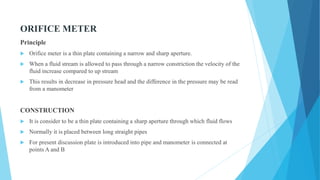
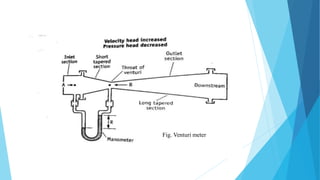
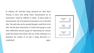
FLOW OF FLUIDS
Presented by:
PRIYA TIWARI
Asst. Professor
Faculty of Pharmaceutical Sciences, Rama University Kanpur
CONTENT
 Fluid flow
 Reynold’s experiment
 Bernoulli’s theorem
 Orifice meter
 Venturimeter
 Pitot tube
 Rotometer
FLUID FLOW
 A fluid is a substance that continually deforms (flows) under an applied shear stress.
 Fluids are a subset of the phases of matter and include liquids, gases.
 Fluid flow may be defined as the flow of substances that do not permanently resist
distortion
 The subject of fluid flow can be divided into fluid static's and fluid dynamics.
FLUID STATICS
 Fluid static's deals with the fluids at rest in equilibrium
 Behaviour of liquid at rest
 Nature of pressure it exerts and the variation of pressure at different layers
FLUID DYNAMICS
 Fluid dynamics deals with the study of fluids in motion
 This knowledge is important for liquids, gels, ointments which will change their flow
behaviour when exposed to different stress conditions
MIXING --------- FLOW THROUGH PIPES ----------- FILLED IN CONTAINER
Importance –
Identification of type of flow is important in-
 Manufacture of dosage forms
 Handling of drugs for administration
 The flow of fluid through a pipe can be viscous or turbulent and it can be determined by
Reynolds number.
REYNOLDS EXPERIMENT
 Prof. Osborne Reynolds conducted the experiment in the year 1883.
 This was conducted to demonstrate the existence of two types of flow :-
1. Laminar Flow 2. Turbulent Flow
 Glass tube is connected to reservoir of water, rate of flow of water is adjusted by a
valve,
 A reservoir of colored solution is connected to one end of the glass tube with help of
nozzle. Colored solution is introduced into the nozzle as fine stream through jet tube.
Reynold’s experiment-
2 types of flow- turbulent
laminar
Types Of Flows Based On Reynold Number -
 If Reynold number, RN < 2000 the flow is laminar flow.
 If Reynold number, RN > 4000 the flow is turbulent flow.
REYNOLDS NUMBER
In Reynolds experiment the flow conditions are affected by-
 Diameter of pipe
 Average velocity
 Density of liquid
 Viscosity of the fluid
 This four factors are combined in one way as Reynolds number
Re= D u ρ INERTIAL FORCES
ʞ VISCOUS FORCES
 Inertial forces are due to mass and the velocity of the fluid particles trying to diffuse the
fluid particles
 viscous force if the frictional force due to the viscosity of the fluid which make the
motion of the fluid in parallel.
 Reynolds number have no unit
APPLICATIONS
 Reynolds number is used to predict the nature of the flow
 Stocks law equation is modified to include Reynolds number to study the rate of
sedimentation in suspension
BERNOULLI'S THEOREM
When the principals of the law of energy is applied to the flow of the fluids the resulting
equation is a Bernoulli's theorem
 Consider a pump working under isothermal conditions between points A and B
 Bernoulli's theorem statement, "In a steady state the total energy per unit mass consists
of pressure, kinetic and potential energies are constant"
At point a one kilogram of liquid is assumed to be entering at point a,
Pressure energy = Pa /g ρA
Where Pa = Pressure at point a
g = Acceleration due to gravity
ρA = Density of the liquid
Potential energy of a body is defined as the energy possessed by the body by the virtue of its
position-
Potential energy = XA
Kinetic energy of a body is defined as the energy possessed by the body by virtue of its motion,
kinetic energy = UA2 / 2g
Total energy at point A = Pressure energy + Potential energy + K. E
Total energy at point A = PaV + XA + UA2 / 2g
According to the Bernoulli's theorem the total energy at point A is constant
Total energy at point A = PAV +XA + (UA2 / 2g) = Constant
After the system reaches the steady state, whenever one kilogram of liquid enters at point
A, another one kilogram of liquid leaves at point B
Total energy at point B = PBV +XB + UB2 / 2g
PAV +XA + (UA2/2g) + Energy added by the pump = PBV +XB + (UB2/2g)
V is volume and it is reciprocal of density.
During the transport some energy is converted to heat due to frictional Forces
Energy loss due to friction in the line = F
Energy added by pump = W
 Pa /ρ A +XA + UA2 / 2g – F + W = PB /ρ B +XB + UB2 / 2g
 This equation is called as Bernoulli's equation
During the transport some energy is converted to heat due to frictional Forces
Energy loss due to friction in the line = F
Energy added by pump = W
 Pa /ρA +XA + UA2 / 2g – F + W = PB /ρ B +XB + UB2 / 2g
 This equation is called as Bernoulli's equation.
ENERGY LOSS –
According to the law of conservation of energy, energy balance have to be properly
calculated . fluids experiences energy losses in several ways while flowing through pipes,
they are
 Frictional losses
 Losses in the fitting
 Enlargement losses
 Contraction losses
Application of BERNOULLI'S THEOREM
 Used in the measurement of rate of fluid flow using flowmeters
 It applied in the working of the centrifugal pump, in this kinetic energy is converted in
to pressure
MANOMETERS
Manometers are the devices used for measuring the pressure difference . Different type of
manometers are
 Simple manometer
 Differential manometer
 Inclined manometer
Simple manometer
 This manometer is the most commonly used one
 It consists of a glass U shaped tube filled with a liquid
A- of density ρA kg /meter cube and above A the arms are filled
with liquid B of density ρB
 The liquid A and B are immiscible and the interference can be
seen clearly
 If two different pressures are applied on the two arms, the meniscus of the one liquid will be
higher than the other
 Let pressure at point 1 will be P1 Pascal's and point 5 will be P2 Pascal's
 The pressure at point 2 can be written as
=P1+ (m + R )ρB g
 since āˆ†P = āˆ† h ρ g (m + R ) = distance from 3 to 5
 Since the points 2 and 3 are at same height the pressure
Pressure at 3 =P1+ (m + R ) ρ B g
 Pressure at 4 is less than pressure at point 3 by R ρA g
 Pressure at 5 is still less than pressure at point 4 by mρ B g
This can be summarise as
 P1 + (m + R ) ρ B g - R ρA g - mρ B g= P2
 āˆ†P= P1-P2=R (ρ A- ρ B )g
Application
 Pressure difference can be determined by measuring R
 Manometers are use in measuring flow of fluid.
DIFFERENTIAL MANOMETERS
 These manometers are suitable for measurement of small pressure differences
 It is also known as two – Fluid U- tube manometer
 It contains two immiscible liquids A and B having nearly same densities
 The U tube contains of enlarged chambers on both limbs,
 Using the principle of simple manometer the pressure differences can be written as
āˆ†P =P1 –P2 =R (ρc – ρA)g
Differential manometer
INCLINED TUBE MANOMETERS
 Many applications require accurate measurement of low pressure such as drafts and
very low differentials, primarily in air and gas installations.
 In these applications the manometer is arranged with the indicating tube inclined,
 This enables the measurement of small pressure changes with increased accuracy.
P1 –P2 = g R (ρ A - ρ B) sin α
ORIFICE METER
Principle
 Orifice meter is a thin plate containing a narrow and sharp aperture.
 When a fluid stream is allowed to pass through a narrow constriction the velocity of the
fluid increase compared to up stream
 This results in decrease in pressure head and the difference in the pressure may be read
from a manometer
CONSTRUCTION
 It is consider to be a thin plate containing a sharp aperture through which fluid flows
 Normally it is placed between long straight pipes
 For present discussion plate is introduced into pipe and manometer is connected at
points A and B
Working
 When fluid is allowed to pass through the orifice the velocity of the fluid at point B
increase, as a result at point A pressure will be increased.
 Difference in the pressure is measured by manometer
 Bernoulli's equation is applied to point A and point B for experimental conditions
Total energy at point A = Pressure energy + Potential energy + K. E
Total energy at point A = PaV + XA + UA2 / 2g
 Bernoullis eqn... Pa /ρ A +XA + UA2 / 2g – F + W = PB /ρB +XB + UB2 / 2g
Assumptions
 Pipeline is horizontal A and B are at same position Therefore XA=XB
 Suppose friction losses are negligible F=0
 As liquid is incompressible so density remain same, Therefore ρ A=ρ B=ρ
 No work is done on liquid therefore w=0
After applying assumptions Bernaoulis eqn...
PA /ρ A +XA + UA2 / 2g – F + W = PB /ρ B +XB + UB2 / 2g
 Change to---
PA /ρ + UA2 / 2g = PB /ρ + UB2 / 2g
UA2 / 2g - UB2 / 2g = PB /ρ - PA /ρ
Multiply both sides by -2g
UB
2 - UA
2 = 2g.PA /ρ - 2g.PB/ρ
√UB2 - UA2 = √2g/ρ . (PA - PB)
√UB2 - UA2 = √2gāˆ†H ........ as (PA - PB)/ρ=āˆ†H
√UB 2 - UA2 = √2gāˆ†H
diameter of vena contracta is not known practically
There are friction losses so above equation is modified to—
√U02 – UA2 =C0 √2g. āˆ†H
If the diameter of orifice is 1/5th of the diameter of pipe then UA 2 is negligible
The velocity of the fluid at thin constriction may be written as -
U0 = C0 √ 2g āˆ†H
 āˆ†H = Difference in pressure head, can be measured by manometer
 C0 = constant c-oefficient of orifice (friction losses)
 U0 = velocity of fluid at the point of orifice meter
Applications
 Velocity at either of the point A and B can be measured
 Volume of liquid flowing per hour can be determined by knowing area of cross
section
VENTURI METER
Principle
 When fluid is allowed to pass through narrow venturi throat then velocity of fluid
increases and pressure decreases
 Difference in upstream and downstream pressure head can be measured by using
Manometer
U v = C v √ 2g . āˆ†H
Why Venturi meter if Orifice meter is available?
 Main disadvantage of orifice meter is power loss due to sudden contraction with
consequent eddies on other side of orifice plate
 We can minimize power loss by gradual contraction of pipe
 Venturi meter consist of two tapperd (conical section) inserted in pipeline
 Friction losses and eddies can be minimized by this arrangement.
ADVANTAGES
 For permanent installations
 Power loss is less
 Head loss is negligible
DISADVANTAGES
 Expensive
 Need technical export
 Not flexible it is permanent
Fig. Venturi meter
PITOT TUBE
A pitot tube is a pressure measurement instrument used to measure fluid flow velocity. The
pitot tube was invented by the French engineer Henri Pitot in the early 18th century and
was modified to its modern form in the mid-19th century by French scientist Henry Darcy.
It is widely used to determine the airspeed of an aircraft, water speed of a boat, and to
measure liquid, air and gas velocities in industrial applications. The pitot tube is used to
measure the local velocity at a given point in the flow stream and not the average velocity
in the pipe or conduit
CONSTRUCTION
 It is also known as insertion meter
 The size of the sensing element is small compared to the flow channel
 One tube is perpendicular to the flow direction and the other is parallel to the flow
 Two tubes are connected to the manometer
2gāˆ†Hp = U2
WORKING
 A pitot tube is simply a small cylinder that faces a fluid so that the fluid can enter it.
Because the cylinder is open on one side and enclosed on the other, fluid entering it
cannot flow any further and comes to a rest inside of the device. A diaphragm inside of
the pitot tube separates the incoming pressure (static pressure) from the stagnation
pressure (total pressure) of a system. The difference between these two measurements
determines the fluid’s rate of flow.
In industry, the velocities being measured are often those
flowing in ducts and tubing where measurements by an
anemometer would be difficult to obtain. In these kinds of
measurements, the most practical instrument to use is the pitot
tube. The pitot tube can be inserted through a small hole in the
duct with the pitot connected to a U-tube water gauge or some
other differential pressure gauge for determining the velocity
inside the ducted wind tunnel. One use of this technique is to
determine the volume of air that is being delivered to a
conditioned space.
Advantages:
 Pitot tubes measure pressure levels in a fluid. They do not contain any moving parts and
routine use does not easily damage them. Also, pitot tubes are small and can be used in
tight spaces that other devices cannot fit into.
Disadvantages:
 Foreign material in a fluid can easily clog pitot tubes and disrupt normal readings as a
result. This is a major problem that has already caused several aircraft to crash and
many more to make emergency landings
ROTAMETER
PRINCIPLE
 It is a variable area meter which works on the principle of upthurst force exerted by
fluid and force of gravity
Construction
 It consists of vertically tapered and transparent tube generally made of glass in which a
plummet is centrally placed with guiding wire.
 Linear scale is etched on glass
 During the flow the plummet rise due to variation in flow
 The upper edge of the plummet is used as an index to note the reading
Advantages:
 No external power or fuel.
 Manufactured of cheap materials.
 Since the area of the flow passage increases as the float moves up the tube, the scale is
approximately linear.
Disadvantages:
 Impact of gravity.
 Accuracy of rotameter.
 Uncertainty of the measurement
fluid flow.pdf

fluid flow.pdf

  • 1.
    FLOW OF FLUIDS Presentedby: PRIYA TIWARI Asst. Professor Faculty of Pharmaceutical Sciences, Rama University Kanpur
  • 2.
    CONTENT  Fluid flow Reynold’s experiment  Bernoulli’s theorem  Orifice meter  Venturimeter  Pitot tube  Rotometer
  • 3.
    FLUID FLOW  Afluid is a substance that continually deforms (flows) under an applied shear stress.  Fluids are a subset of the phases of matter and include liquids, gases.  Fluid flow may be defined as the flow of substances that do not permanently resist distortion  The subject of fluid flow can be divided into fluid static's and fluid dynamics.
  • 4.
    FLUID STATICS  Fluidstatic's deals with the fluids at rest in equilibrium  Behaviour of liquid at rest  Nature of pressure it exerts and the variation of pressure at different layers FLUID DYNAMICS  Fluid dynamics deals with the study of fluids in motion  This knowledge is important for liquids, gels, ointments which will change their flow behaviour when exposed to different stress conditions MIXING --------- FLOW THROUGH PIPES ----------- FILLED IN CONTAINER
  • 5.
    Importance – Identification oftype of flow is important in-  Manufacture of dosage forms  Handling of drugs for administration  The flow of fluid through a pipe can be viscous or turbulent and it can be determined by Reynolds number.
  • 6.
    REYNOLDS EXPERIMENT  Prof.Osborne Reynolds conducted the experiment in the year 1883.  This was conducted to demonstrate the existence of two types of flow :- 1. Laminar Flow 2. Turbulent Flow  Glass tube is connected to reservoir of water, rate of flow of water is adjusted by a valve,  A reservoir of colored solution is connected to one end of the glass tube with help of nozzle. Colored solution is introduced into the nozzle as fine stream through jet tube.
  • 7.
  • 8.
    2 types offlow- turbulent laminar
  • 9.
    Types Of FlowsBased On Reynold Number -  If Reynold number, RN < 2000 the flow is laminar flow.  If Reynold number, RN > 4000 the flow is turbulent flow. REYNOLDS NUMBER In Reynolds experiment the flow conditions are affected by-  Diameter of pipe  Average velocity  Density of liquid  Viscosity of the fluid
  • 10.
     This fourfactors are combined in one way as Reynolds number Re= D u ρ INERTIAL FORCES ʞ VISCOUS FORCES  Inertial forces are due to mass and the velocity of the fluid particles trying to diffuse the fluid particles  viscous force if the frictional force due to the viscosity of the fluid which make the motion of the fluid in parallel.  Reynolds number have no unit
  • 11.
    APPLICATIONS  Reynolds numberis used to predict the nature of the flow  Stocks law equation is modified to include Reynolds number to study the rate of sedimentation in suspension
  • 12.
    BERNOULLI'S THEOREM When theprincipals of the law of energy is applied to the flow of the fluids the resulting equation is a Bernoulli's theorem  Consider a pump working under isothermal conditions between points A and B  Bernoulli's theorem statement, "In a steady state the total energy per unit mass consists of pressure, kinetic and potential energies are constant"
  • 13.
    At point aone kilogram of liquid is assumed to be entering at point a, Pressure energy = Pa /g ρA Where Pa = Pressure at point a g = Acceleration due to gravity ρA = Density of the liquid Potential energy of a body is defined as the energy possessed by the body by the virtue of its position- Potential energy = XA Kinetic energy of a body is defined as the energy possessed by the body by virtue of its motion, kinetic energy = UA2 / 2g
  • 14.
    Total energy atpoint A = Pressure energy + Potential energy + K. E Total energy at point A = PaV + XA + UA2 / 2g According to the Bernoulli's theorem the total energy at point A is constant Total energy at point A = PAV +XA + (UA2 / 2g) = Constant After the system reaches the steady state, whenever one kilogram of liquid enters at point A, another one kilogram of liquid leaves at point B Total energy at point B = PBV +XB + UB2 / 2g PAV +XA + (UA2/2g) + Energy added by the pump = PBV +XB + (UB2/2g) V is volume and it is reciprocal of density.
  • 15.
    During the transportsome energy is converted to heat due to frictional Forces Energy loss due to friction in the line = F Energy added by pump = W  Pa /ρ A +XA + UA2 / 2g – F + W = PB /ρ B +XB + UB2 / 2g  This equation is called as Bernoulli's equation
  • 16.
    During the transportsome energy is converted to heat due to frictional Forces Energy loss due to friction in the line = F Energy added by pump = W  Pa /ρA +XA + UA2 / 2g – F + W = PB /ρ B +XB + UB2 / 2g  This equation is called as Bernoulli's equation.
  • 17.
    ENERGY LOSS – Accordingto the law of conservation of energy, energy balance have to be properly calculated . fluids experiences energy losses in several ways while flowing through pipes, they are  Frictional losses  Losses in the fitting  Enlargement losses  Contraction losses Application of BERNOULLI'S THEOREM  Used in the measurement of rate of fluid flow using flowmeters  It applied in the working of the centrifugal pump, in this kinetic energy is converted in to pressure
  • 18.
    MANOMETERS Manometers are thedevices used for measuring the pressure difference . Different type of manometers are  Simple manometer  Differential manometer  Inclined manometer
  • 19.
    Simple manometer  Thismanometer is the most commonly used one  It consists of a glass U shaped tube filled with a liquid A- of density ρA kg /meter cube and above A the arms are filled with liquid B of density ρB  The liquid A and B are immiscible and the interference can be seen clearly  If two different pressures are applied on the two arms, the meniscus of the one liquid will be higher than the other
  • 20.
     Let pressureat point 1 will be P1 Pascal's and point 5 will be P2 Pascal's  The pressure at point 2 can be written as =P1+ (m + R )ρB g  since āˆ†P = āˆ† h ρ g (m + R ) = distance from 3 to 5  Since the points 2 and 3 are at same height the pressure Pressure at 3 =P1+ (m + R ) ρ B g  Pressure at 4 is less than pressure at point 3 by R ρA g  Pressure at 5 is still less than pressure at point 4 by mρ B g
  • 21.
    This can besummarise as  P1 + (m + R ) ρ B g - R ρA g - mρ B g= P2  āˆ†P= P1-P2=R (ρ A- ρ B )g Application  Pressure difference can be determined by measuring R  Manometers are use in measuring flow of fluid.
  • 22.
    DIFFERENTIAL MANOMETERS  Thesemanometers are suitable for measurement of small pressure differences  It is also known as two – Fluid U- tube manometer  It contains two immiscible liquids A and B having nearly same densities  The U tube contains of enlarged chambers on both limbs,  Using the principle of simple manometer the pressure differences can be written as āˆ†P =P1 –P2 =R (ρc – ρA)g
  • 23.
  • 24.
    INCLINED TUBE MANOMETERS Many applications require accurate measurement of low pressure such as drafts and very low differentials, primarily in air and gas installations.  In these applications the manometer is arranged with the indicating tube inclined,  This enables the measurement of small pressure changes with increased accuracy. P1 –P2 = g R (ρ A - ρ B) sin α
  • 26.
    ORIFICE METER Principle  Orificemeter is a thin plate containing a narrow and sharp aperture.  When a fluid stream is allowed to pass through a narrow constriction the velocity of the fluid increase compared to up stream  This results in decrease in pressure head and the difference in the pressure may be read from a manometer CONSTRUCTION  It is consider to be a thin plate containing a sharp aperture through which fluid flows  Normally it is placed between long straight pipes  For present discussion plate is introduced into pipe and manometer is connected at points A and B
  • 27.
    Working  When fluidis allowed to pass through the orifice the velocity of the fluid at point B increase, as a result at point A pressure will be increased.  Difference in the pressure is measured by manometer  Bernoulli's equation is applied to point A and point B for experimental conditions Total energy at point A = Pressure energy + Potential energy + K. E Total energy at point A = PaV + XA + UA2 / 2g  Bernoullis eqn... Pa /ρ A +XA + UA2 / 2g – F + W = PB /ρB +XB + UB2 / 2g
  • 28.
    Assumptions  Pipeline ishorizontal A and B are at same position Therefore XA=XB  Suppose friction losses are negligible F=0  As liquid is incompressible so density remain same, Therefore ρ A=ρ B=ρ  No work is done on liquid therefore w=0 After applying assumptions Bernaoulis eqn... PA /ρ A +XA + UA2 / 2g – F + W = PB /ρ B +XB + UB2 / 2g  Change to--- PA /ρ + UA2 / 2g = PB /ρ + UB2 / 2g UA2 / 2g - UB2 / 2g = PB /ρ - PA /ρ
  • 29.
    Multiply both sidesby -2g UB 2 - UA 2 = 2g.PA /ρ - 2g.PB/ρ √UB2 - UA2 = √2g/ρ . (PA - PB) √UB2 - UA2 = √2gāˆ†H ........ as (PA - PB)/ρ=āˆ†H √UB 2 - UA2 = √2gāˆ†H diameter of vena contracta is not known practically There are friction losses so above equation is modified to— √U02 – UA2 =C0 √2g. āˆ†H
  • 30.
    If the diameterof orifice is 1/5th of the diameter of pipe then UA 2 is negligible The velocity of the fluid at thin constriction may be written as - U0 = C0 √ 2g āˆ†H  āˆ†H = Difference in pressure head, can be measured by manometer  C0 = constant c-oefficient of orifice (friction losses)  U0 = velocity of fluid at the point of orifice meter Applications  Velocity at either of the point A and B can be measured  Volume of liquid flowing per hour can be determined by knowing area of cross section
  • 32.
    VENTURI METER Principle  Whenfluid is allowed to pass through narrow venturi throat then velocity of fluid increases and pressure decreases  Difference in upstream and downstream pressure head can be measured by using Manometer U v = C v √ 2g . āˆ†H
  • 33.
    Why Venturi meterif Orifice meter is available?  Main disadvantage of orifice meter is power loss due to sudden contraction with consequent eddies on other side of orifice plate  We can minimize power loss by gradual contraction of pipe  Venturi meter consist of two tapperd (conical section) inserted in pipeline  Friction losses and eddies can be minimized by this arrangement.
  • 34.
    ADVANTAGES  For permanentinstallations  Power loss is less  Head loss is negligible DISADVANTAGES  Expensive  Need technical export  Not flexible it is permanent
  • 35.
  • 36.
    PITOT TUBE A pitottube is a pressure measurement instrument used to measure fluid flow velocity. The pitot tube was invented by the French engineer Henri Pitot in the early 18th century and was modified to its modern form in the mid-19th century by French scientist Henry Darcy. It is widely used to determine the airspeed of an aircraft, water speed of a boat, and to measure liquid, air and gas velocities in industrial applications. The pitot tube is used to measure the local velocity at a given point in the flow stream and not the average velocity in the pipe or conduit
  • 37.
    CONSTRUCTION  It isalso known as insertion meter  The size of the sensing element is small compared to the flow channel  One tube is perpendicular to the flow direction and the other is parallel to the flow  Two tubes are connected to the manometer 2gāˆ†Hp = U2
  • 38.
    WORKING  A pitottube is simply a small cylinder that faces a fluid so that the fluid can enter it. Because the cylinder is open on one side and enclosed on the other, fluid entering it cannot flow any further and comes to a rest inside of the device. A diaphragm inside of the pitot tube separates the incoming pressure (static pressure) from the stagnation pressure (total pressure) of a system. The difference between these two measurements determines the fluid’s rate of flow.
  • 39.
    In industry, thevelocities being measured are often those flowing in ducts and tubing where measurements by an anemometer would be difficult to obtain. In these kinds of measurements, the most practical instrument to use is the pitot tube. The pitot tube can be inserted through a small hole in the duct with the pitot connected to a U-tube water gauge or some other differential pressure gauge for determining the velocity inside the ducted wind tunnel. One use of this technique is to determine the volume of air that is being delivered to a conditioned space.
  • 40.
    Advantages:  Pitot tubesmeasure pressure levels in a fluid. They do not contain any moving parts and routine use does not easily damage them. Also, pitot tubes are small and can be used in tight spaces that other devices cannot fit into. Disadvantages:  Foreign material in a fluid can easily clog pitot tubes and disrupt normal readings as a result. This is a major problem that has already caused several aircraft to crash and many more to make emergency landings
  • 41.
    ROTAMETER PRINCIPLE  It isa variable area meter which works on the principle of upthurst force exerted by fluid and force of gravity
  • 42.
    Construction  It consistsof vertically tapered and transparent tube generally made of glass in which a plummet is centrally placed with guiding wire.  Linear scale is etched on glass  During the flow the plummet rise due to variation in flow  The upper edge of the plummet is used as an index to note the reading
  • 44.
    Advantages:  No externalpower or fuel.  Manufactured of cheap materials.  Since the area of the flow passage increases as the float moves up the tube, the scale is approximately linear. Disadvantages:  Impact of gravity.  Accuracy of rotameter.  Uncertainty of the measurement