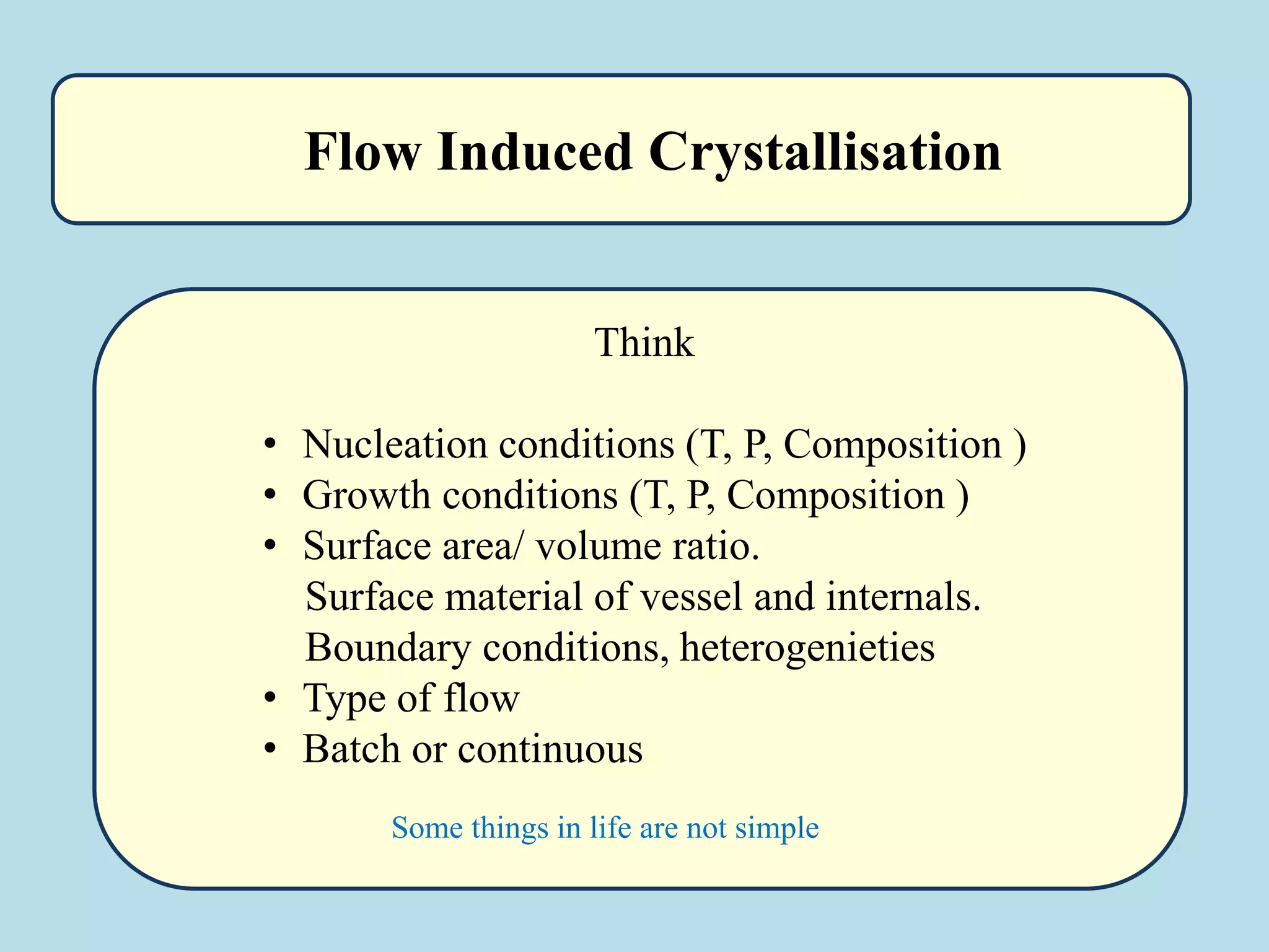
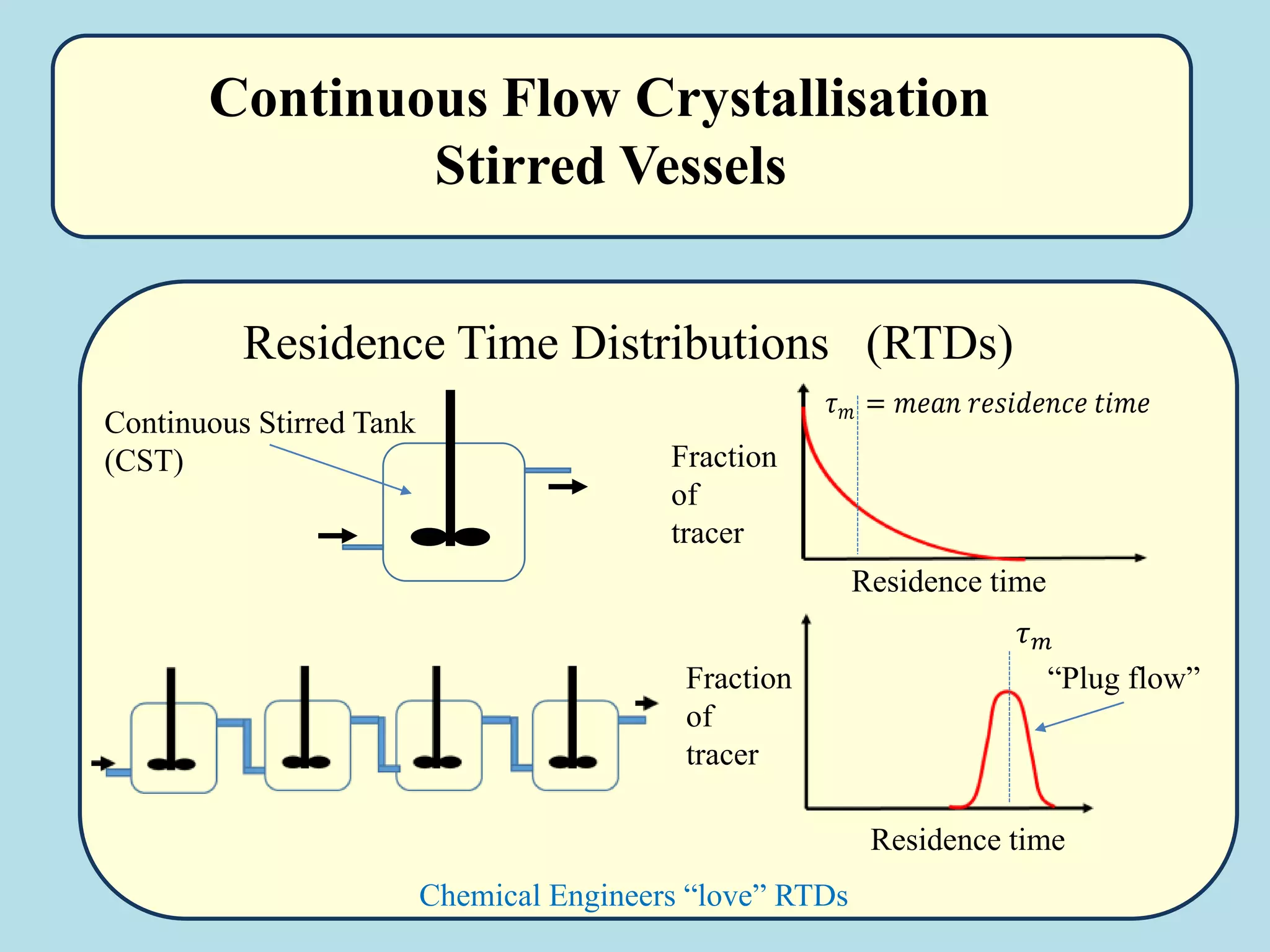
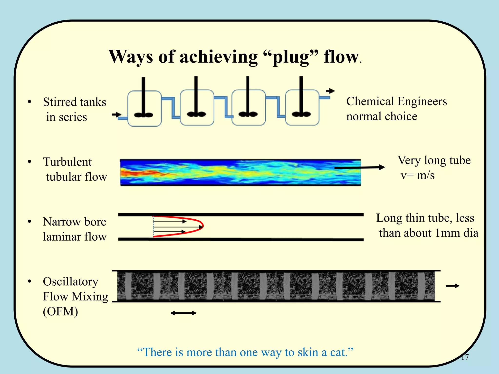
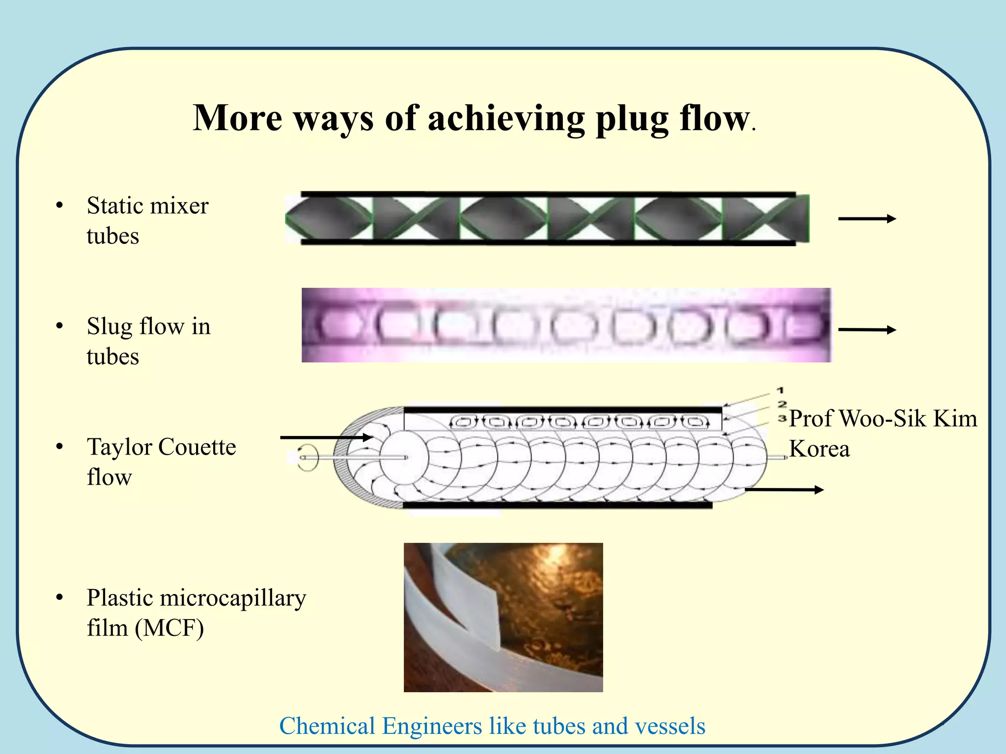
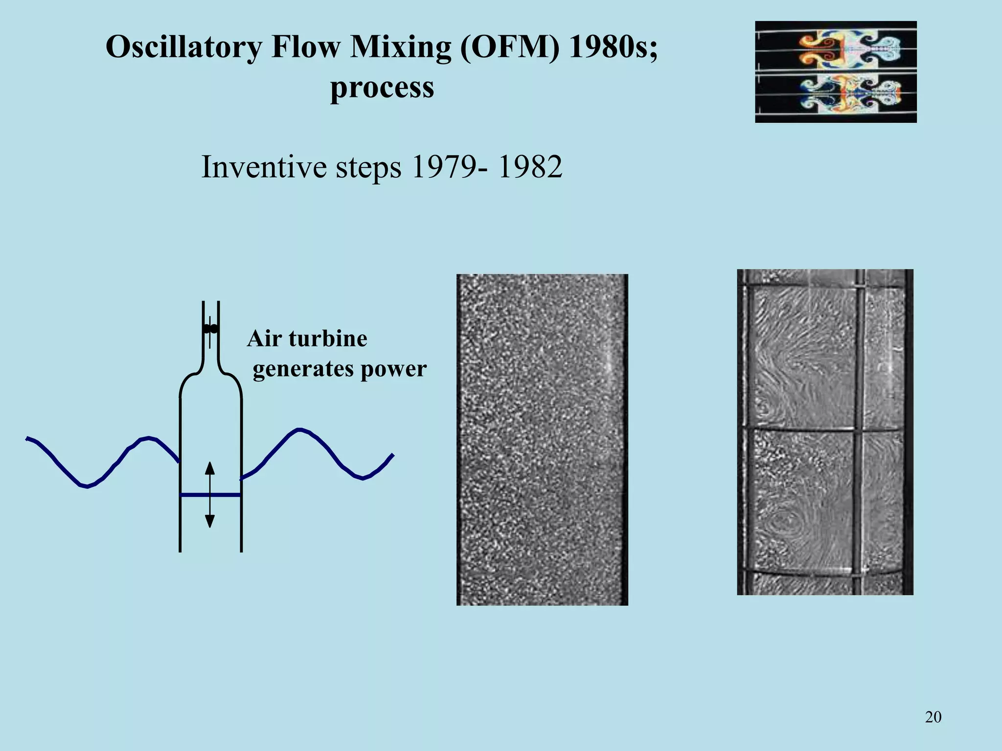
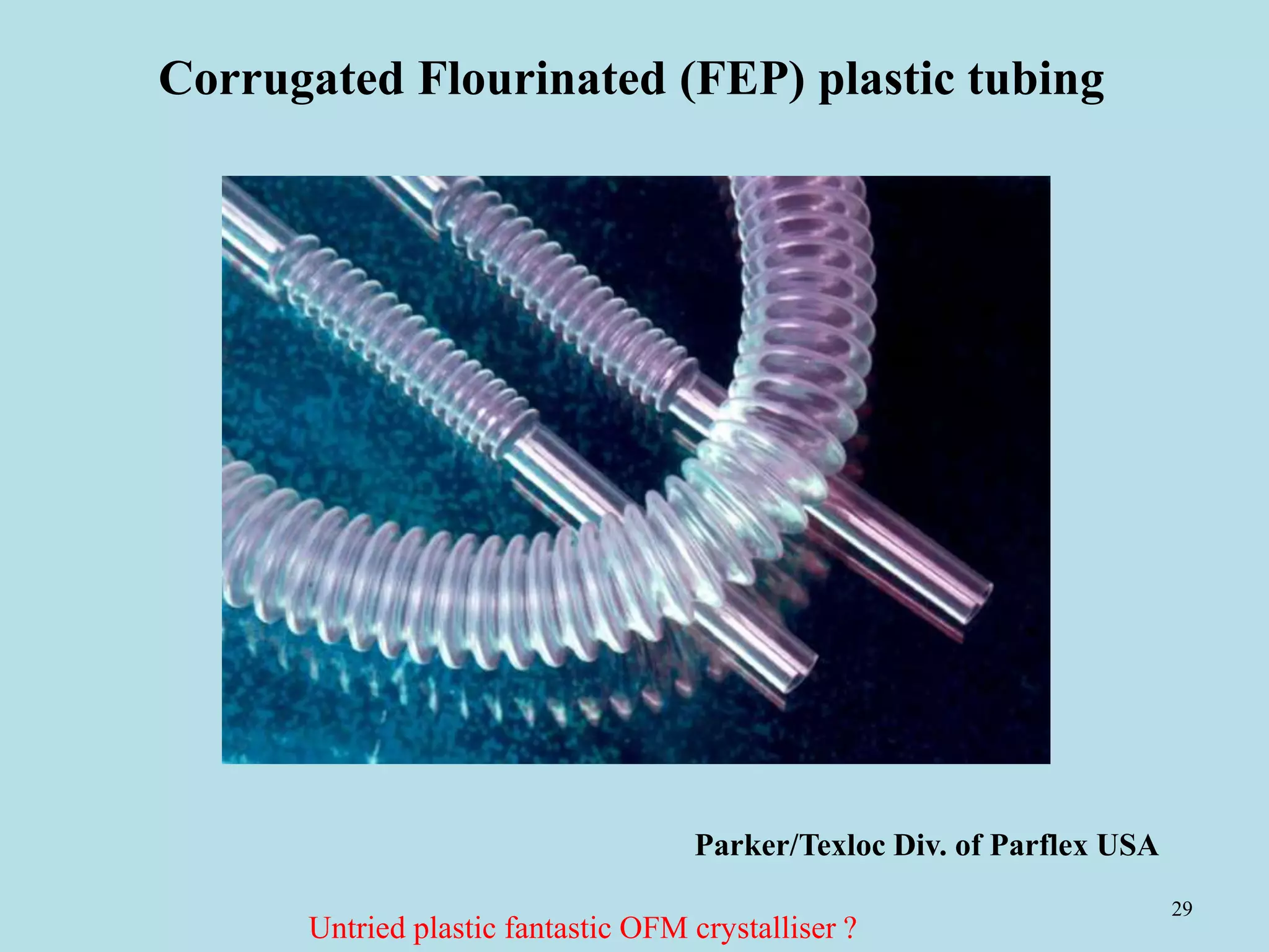
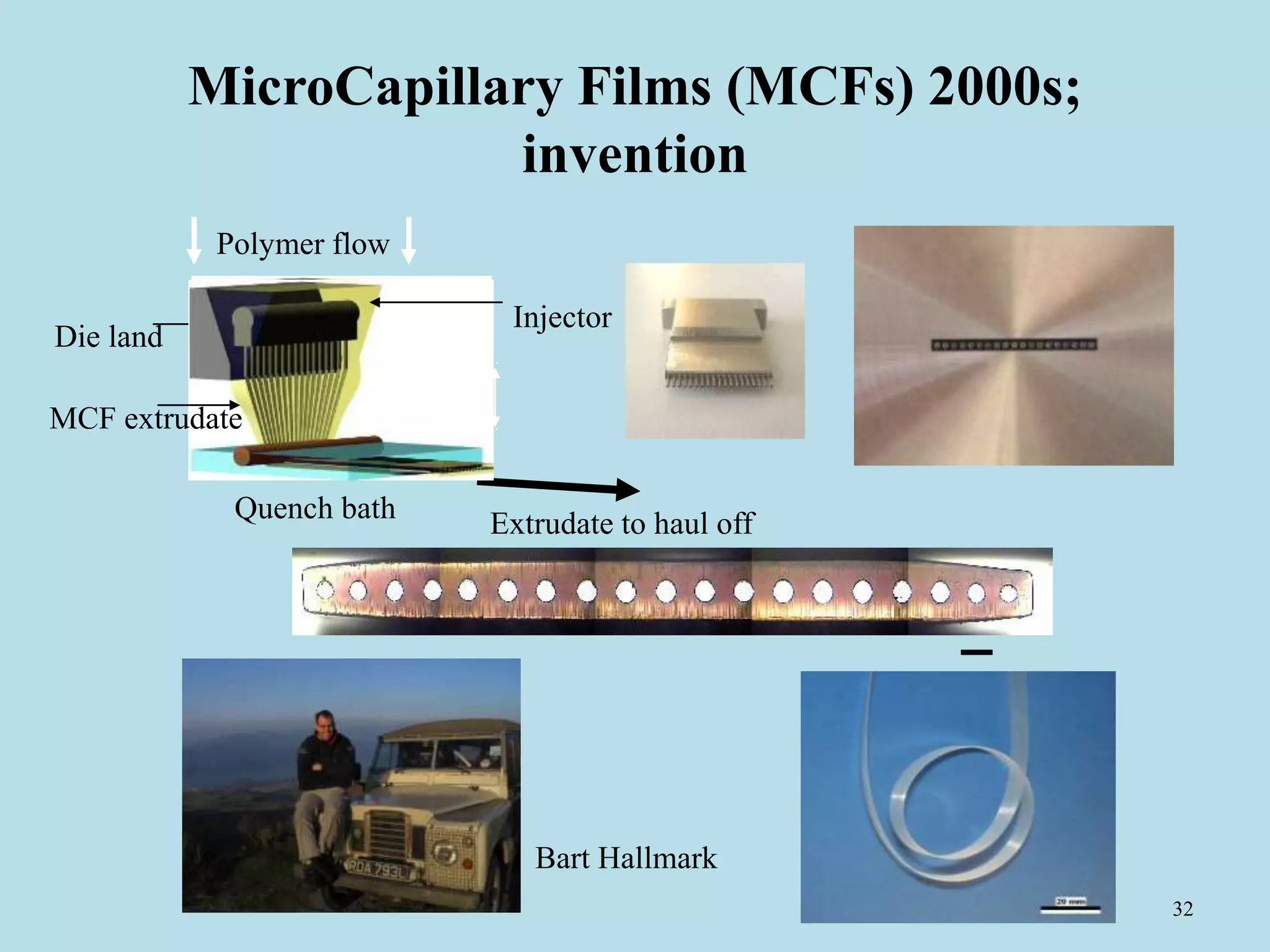
The document discusses the principles of crystallization and flow processing, emphasizing the impact of various flow types on crystallization, particularly for polyethylene. It outlines key concepts such as shear and extensional flow, crystallization mechanisms, and methods for achieving plug flow in continuous systems. Additionally, advancements like oscillatory flow mixing and microcapillary films are highlighted as innovative approaches to enhance crystallization efficiency and control in industrial applications.
![35
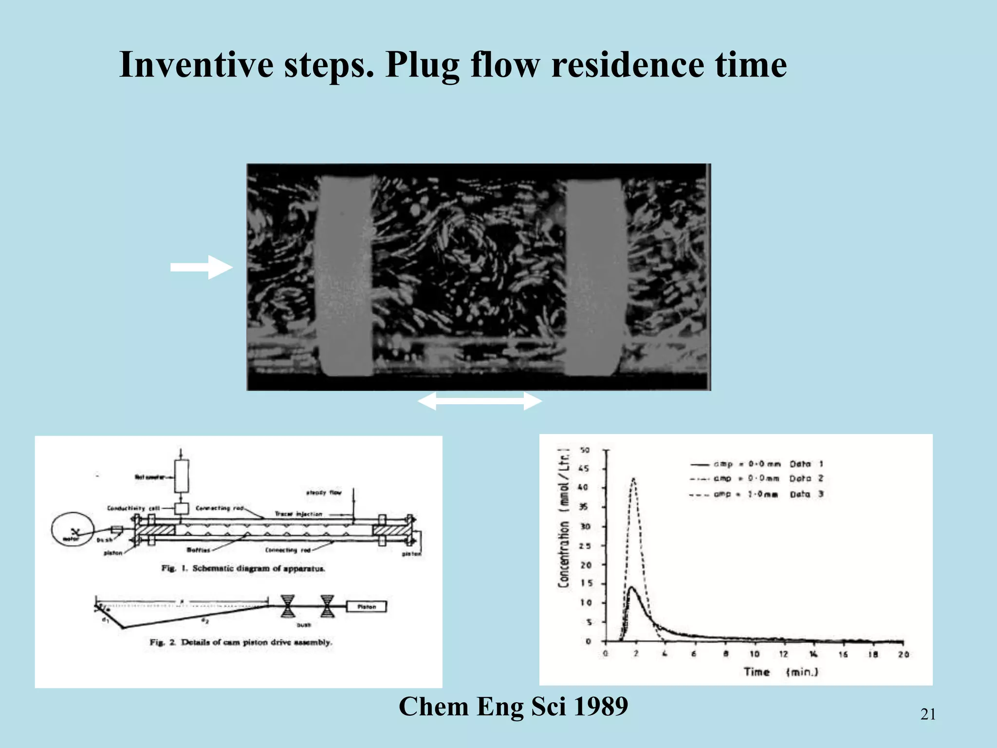
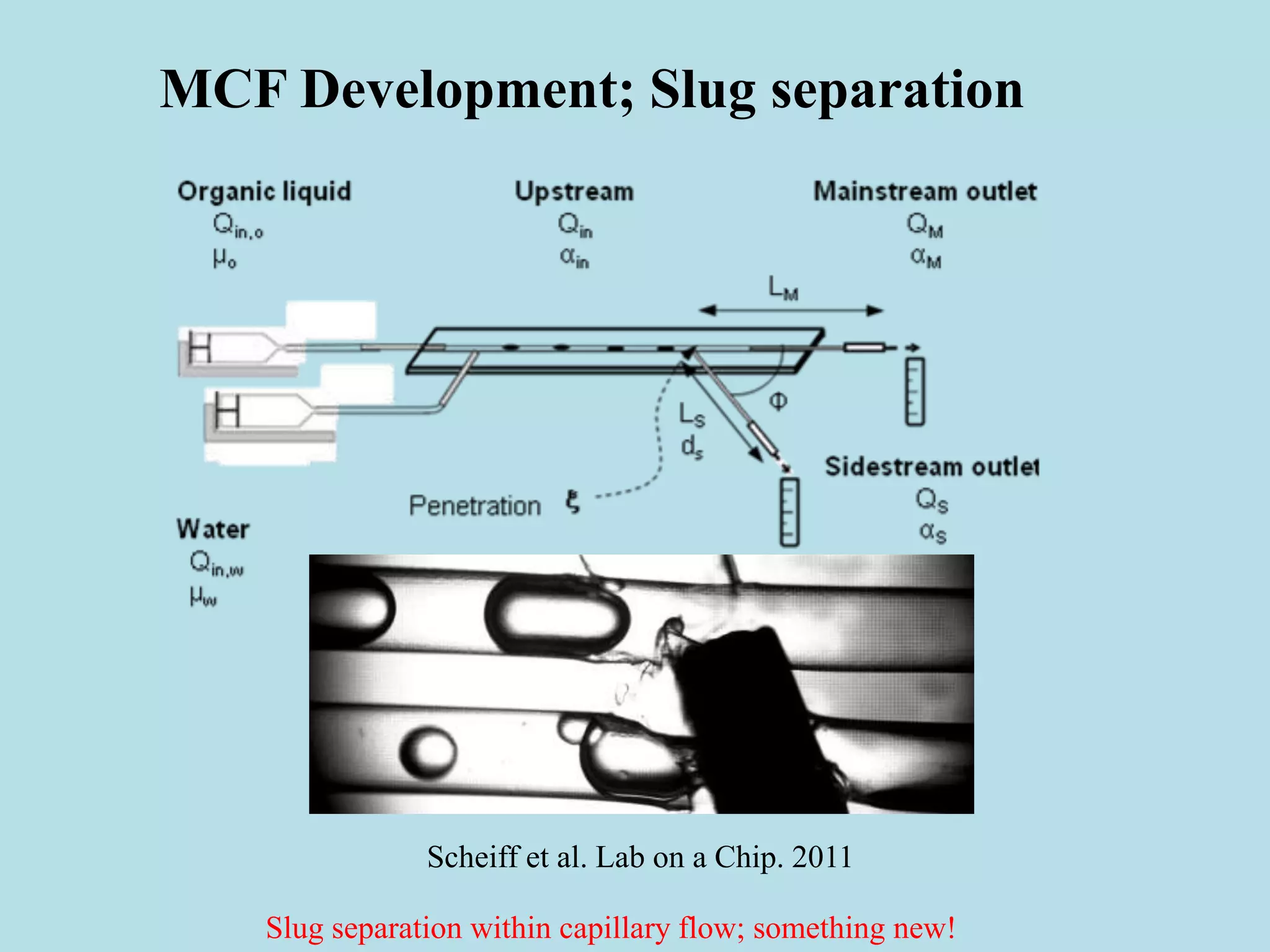
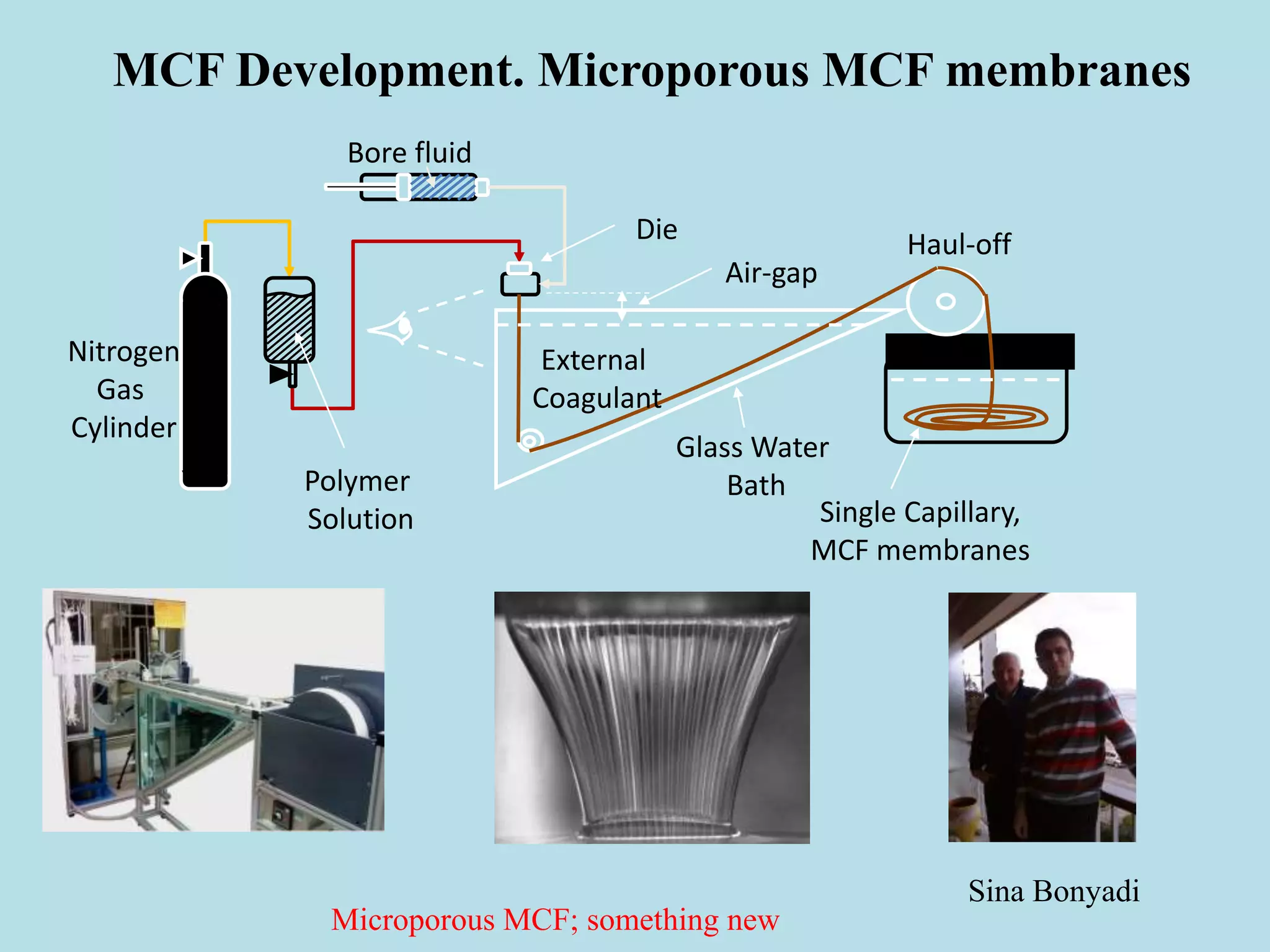
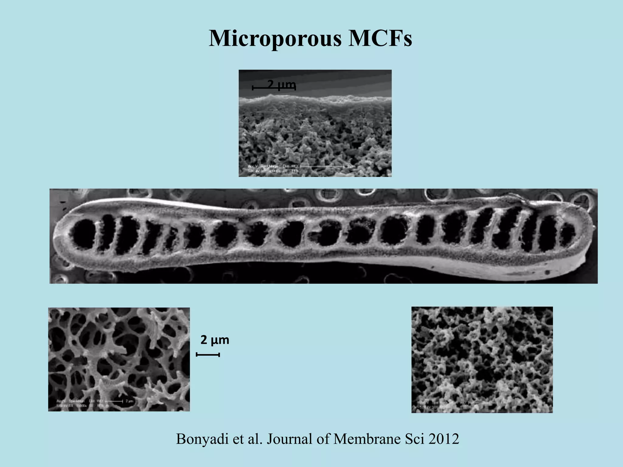
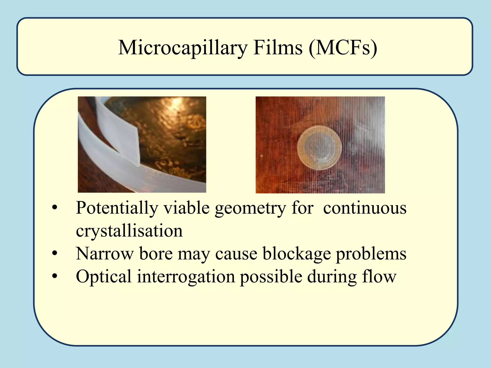
MCF Development RTD
0
5
10
15
20
25
30
35
40
45
50
0 5 10 15 20 25 30
t [min]
c[mg/l]
inlet
outlet
length = 20 m
flow rate = 0.5 ml/min
Plug flow, laminar flow MCF! Radial dispersion through molecular diffusion](https://image.slidesharecdn.com/crystal-flow-processing-1-2014-140524060427-phpapp02/75/Flow-Crystallisation-and-Continuous-Processing-35-2048.jpg)


![Coded Agents – with UiPath SDK + LangGraph [Virtual Hands-on Workshop]](https://cdn.slidesharecdn.com/ss_thumbnails/codedagentsdeck-251215155422-5497c599-thumbnail.jpg?width=640&height=640&fit=bounds)


