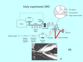
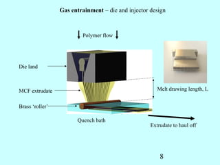
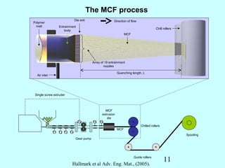
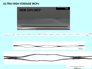
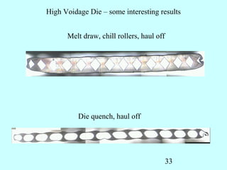
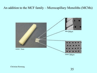
LG. Korea 2012

“Inventing Plastic Microcapillary Films”
                        BY
             MALCOLM MACKLEY.
             With Acknowledgement to;
                   Dr Bart Hallmark
               Dr Christian Hornung
                     Dora Medina
            Sina Bonyadi and Hui Cheah
                      Nuno Reis
 Frederik Scheiff, David Agar and Matthais Mendorf

 DEPARTMENT OF CHEMICAL ENGINEERING AND
            BIOTECHNOLOGY.
        UNIVERSITY OF CAMBRIDGE.

               mrm5@cam.ac.uk             1
Plastic Fantastic

Sub millimetre Process Engineering


                             2
Conventional Foaming Processing
                            high
                            pressure
                            gas
               hopper                        metering
                                             device
                                                        static mixer   nucleation
               Polymer
plasticating
screw


                                   Band
                                   heaters
                    Plastication              Polymer/gas solution          Nucleation
                    of polymer                     formation                 and Cell
                                                                              growth


                                                                                    3
Background.
Plastic Micro Capillary Films
           (MCFs)


                    Bart Hallmark and Malcolm Mackley 2005
                                         4
5
Early experiments 2002
                                                                                                          Gas injector

                                                                                                          Convergent die

                                                                                                          Edge of quartz window
                              Hopper
                                                     Flange
                                                     with filter
                                                             P2         T5   T6
                  Motor                     Screw
                                                                                  T7

                                       T1   T2 T3     T4                           P1
                                                            Gear pump
                                            Heated                                     Die
                                            barrel
                                                                         F                         Haul off

Nitrogen supply
                                  Secondary                         Rotameter          Hollow extrudate
                      Primary
                      pressure     pressure             Gas flow
                      regulator    regulator             control


                                                                                                          PE


                                                                                             6
MCF Process Development


                                                                           Gas entrainment

                                                                           Convergent die

                                                                           Edge of quartz window
         Hopper
                             Flange
                             with filter
                                     P2         T5   T6
Motor               Screw
                                                          T7

               T1    T2 T3    T4                           P1
                                    Gear pump
                    Heated                                     Die
                    barrel
                                                                              Haul off

                                                                         Hollow extrudate


        Hallmark et al. J. Non-Newtonian Fluid. Mech (2005)
                                                                     7
Gas entrainment – die and injector design


                         Polymer flow


Die land


MCF extrudate                                          Melt drawing length, L


Brass ‘roller’

                       Quench bath
                                                    Extrudate to haul off


                                                        8
Low voidage MCF


              9
Die design


             10
The MCF process
                            Die exit                   Direction of flow
Polymer
 melt            Entrainment
                                                                                       Chill rollers
                    body
                                                               MCF


                                        Array of 19 entrainment
                                                nozzles
                                                     PLAN VIEW
                                                          Quenching length, L
  Air inlet


 Single screw extruder


                                              MCF
                                            extrusion
                                                die
                               P2       T5 T6
                                                                           Chilled rollers
                                                         MCF
              T1 T2 T3 T4
                                                                                                       Spooling
                            Gear pump


                                                                      Guide rollers
                                                                                             11
                         Hallmark et al Adv. Eng. Mat., (2005).
Initial die voidage
                              A2
                      φ1 =                = 9.6 %
   A1                      A1 + A3


        A2                 A2 + A3        = 10.3%
              A3      φ2 =
                              A1
                                     12
Low Voidage MCF


                                                                    Standard MCF

                                  250


                                  200
        Hydraulic diameter (μm)


                                  150


                                  100


                                  50


                                   0
                                        1   2   3   4   5   6   7    8     9    10   11      12   13   14   15   16   17   18   19
                                                                         Capillary num ber


                                                                                                                                340 μm


MCF voidage ≈ 9-11 %                                                                                                   13
Drawing Low Voidage MCF


D. I. Medina B. Hallmark T. D. Lord M. R. Mackley The development of voidage and capillary size within extruded plastic films. J
Mat Sci, in press
                                                                                                 14
Mechanical Drawing of MCFs
                (using stable Microsystems texture analyser)


        Upper
        Clamp

                                                  Upper Clamp


MCF


                                                    MCF


Fixed
lower
clamp                                               Fixed
                                                    lower
                                                    clamp


                                 Room
                                 Temperature


                     Mechanical drawing process
                     - Increases orientation but
                                          15
                       limits drawability
Diameters after Mechanical Drawing of MCFs


                          210
                          200
                          190
                          180                                                    Standard MCF
                          170
                          160
                          150
Hydraulic diameter (μm)


                          140
                          130
                          120
                          110
                          100
                           90
                           80
                           70
                           60
                           50
                           40                    Diameters after Mechanical Drawing
                           30
                           20
                           10
                            0
                                0   1    2   3   4   5   6   7   8      9   10   11   12   13   14   15   16   17   18   19   20
                                                                     Capillary number


                                                                                                                    16
COLD DRAWN
                                                                                                                            Necking


                          120
                                                                                                                                      Undrawn
                                                                                                                                      material
                          100
                                                                                                                                      Material
Hydraulic diameter (μm)


                          80                                                                                                          in neck

                          60
                                                                                                                                      Post-neck
                                                                                                                                      material
                          40


                          20


                            0
                                1   2   3   4   5   6    7   8     9    10   11     12   13   14   15   16   17   18   19
                                                                 Capillary number


                                                        MCF voidage ≈ 8.5 %
                                                                                                                       17
HOT DRAWN

                          25
                                                                                                                       Optic micrograph
                                                                                                                       of top view MCFs
                          20
                                                                                                                                Drawing
Hydraulic diameter (μm)


                                                                                                                                direction
                          15


                          10


                          5


                          0
                               1   2   3   4   5   6    7   8   9   10   11   12   13   14   15   16   17   18   19

                                                            Capillary number


                                                       MCF voidage ≈ 9-11 %
                                                                                                                      18
Molecular orientation
                                  Quenching                                                           X-Ray diffraction


                             Extrusion die


                                                                                                                          little orientation
                  Extruder              Melt T=170 °C


                                                                                    Chilled rolls
                                                                                            9 °C


                                             MCF


                                                                                                                          High orientation
     Hot drawing
                                                                       Solid
       - Second stage
          Hot draw-


Thermal camera image
                                                    V2
                                                                                                         V1


                                                                               Draw ratio λ = V1/V2
                                                        Hot roll
                                                        T = 60-120°C                          19
Optic micrograph                    Drawing
MCF Product from                                                   of top view MCFs                    direction
continuous drawing


                                                                                                                  100 μm
                                           200
                                           180
                 Hydraulic diameter (μm)
                                           160
                                           140
                                           120
                                           100
                                            80
                                            60
                                            40
                                            20
                                            0
                                                 0 1   2 3   4 5    6 7    8 9 10 11 12 13 14 15 16 17 18 19 20
                                                                          Capillary number


                                                                                                20
High Voidage MCF


   D Medina J Mat Sci 2008
                             21
High Voidage MCFs
By rapid cooling and or injecting air under pressure into
capillaries during melt processing it is possible to produce                                                       Develop orientation
“High voidage MCFs”


                   Conventional extrusion line                                  MCF         High-
                                                                                extrusion   speed
                                                                                die         air
                                                                                            quench


                                                   P2          T5 T6
                                                                                                 Chilled rollers

                               T1 T2 T3 T4
                                                                                        T                                 Spooling
                                                                   P                    P

                                                   Mass flow control valve
      Compressed
      air                                                                                   Guide rollers
                            Isolation                                  Needle
                              valve                                     valve

                                  P              Pressure sensor                            Manual valve

                                  T              Temperature sensor                         Control valve
                                                                                                             22
High voidage MCFs


                                                                Hydraulic diameter varies from
               200 µm                                           150 μm to 417 μm


                                                                                                                                 100 μm


                                                                             MCF-MCF hv2- big voidage


                                                  350

                                                  300
                        Hydraulic diameter (μm)


                                                  250

                                                  200


                                                  150

                                                  100

                                                  50

                                                   0
                                                        1   2    3   4   5    6   7   8   9   10   11   12   13   14   15   16   17   18   19
                                                                                                   23
                                                                                      Capillary number
X-Ray                                          (200)


                                                                                                      (110)

                                             Orientation present


                           Air quench jet

              Die exit
                                            Solid MCF


Air entrainment
needle


                                                Extrusion direction

                                      Solidification
                                      Interface zone                                  Melt residence time << 1 s
                  Molten
                                                                                      Melt relaxation time < 1 s
                  MCF                                                 Chill rollers
                           Air quench jet

                                                                                             24
High-voidage MCF                                Air quench jet


                                   Die exit                      Solid MCF


                     Air entrainment
                     needle


                                                                     Extrusion direction

                                                           Solidification
                                                           interface

                                       Molten
                                       MCF
                                                                                           Chill rollers
                                                Air quench jet

2D schematic
                                                  Asymmetry in temperature profile  Asymmetry in
                                                  viscosity profile  Asymmetry in the velocity profile

                                                                                           To << Ti
                                                                                           ηo >> ηi
                                                                            ηo T o
            A1, u1                                                                                                   A2, u2
                                                                            ηi T i


 Injector needle                                                                                           25Symmetry plane
Ultra High Voidage MCF


D. I. Medina B. Hallmark T. D. Lord M. R. Mackley The development of voidage and capillary size within extruded plastic films.
J Mat Sci, in press
                                                                                              26
Mechanical drawing of High Voidage
                                   MCFs
                             Capillary direction
                    Upper
                    Clamp

                                                  Upper Clamp


MCF


                                                    MCF


Fixed
lower
clamp                                               Fixed
                                                    lower
                                                    clamp


                                    Room
                                    Temperature


        It breaks
                                             27
Mechanical drawing of MCFs
            Transverse direction
           Upper
           Clamp


                              Upper Clamp

                             MCF
                              Fixed
                              lower
 MCF                          clamp


Fixed
lower
clamp


                      28
HV-MCF is unfolded to form
                   the UHV-MCF


              Go to MCF UHV movie


Dora Medina                                 29
ULTRA HIGH VOIDAGE MCFs

          SEM UHV-MCF


                                             1000 μm


                                   1000 μm


                          30
                               1000 μm
High Voidage die


Bart Hallmark 2008

                                        31
Initial die voidage
                              A2
                      φ1 =                = 30%
   A1                      A1 + A3


        A2                 A2 + A3        = 60%
              A3      φ2 =
                              A1
                                     32
High Voidage Die – some interesting results


      Melt draw, chill rollers, haul off


          Die quench, haul off


                                           33
Microcapillary Monoliths


                    34
An addition to the MCF family – Microcapillary Monoliths (MCMs)


                                             200μm


                7mm


                                              500μm


    Christian Hornung
                                               35
Plastic Fantastic

MCF applications


                    36
MCF Development; Pressure Drop


      Christian Hornung   37
MCF Development RTD
                             PE, EVOH and FEP

                    50
                    45           length = 20 m                           inlet
                                 flow rate = 0.5 ml/min                  outlet
                    40
                    35
                    30


         c [mg/l]
                    25
                    20
                    15
                    10
                    5
                    0
                         0   5           10             15     20   25            30
                                                     t [min]


                                                     38
MCF Commercialisation
   2 flat silicon heaters (200 W each)
    PID control - Temperature monitoring at top and bottom heater
    plates
                                                             developed by
   Tmax = 150 °C                                            Lamina Dielectrics Ltd.
                                                             & Cambridge University


        Reactor disk tray


                                                         Temperature control
                                         Teflon coated
                                         hot plates


     Patrick Hestor Lamina Ltd                              39
MCF Development; Microflow


                                                Video,
                                                Methanol         Nuno Reis
Organic.                                        into Veg oil
Kerosene, 1.8 mPas
Oil,      27 mPas
Vegetable oil. 50 mPas


                         Water, 1 mPas, glycerol 10-50 mPas or methanol
                                                         40
MCF Development; Slug separation


         Scheiff et al. Lab on a Chip. 2011   41
Multi channel flow


            Go to MCF multi channel flow


Nuno Reis
                                           42
MCF Development; Biodiesel Microreactor
   Input                                          Output


Vegetable oil                                       Biodiesel


  Methonal plus                               Glycerol
  catalyst


  Microcapillary
  Flow disc


                                         43
MCF Microreactor; Biodiesel
          Methanol                                 Glycerol
Veg oil

                                                              Biodiesel


   Methanol plus                       Glycerol
   catalyst


                                                  44
MCF Protein Assay
 Nuno Reis and Al Edwards

                               FEP/EVOH


A Edwards et al Lab on a Chip 2011
                                45
MCF Development. Microporous MCF membranes
              Bore fluid                  PVDF/NMP (18/82 wt
                                  Die     %)
                                                        Haul-off
                                          Air-gap

Nitrogen                    External
  Gas                      Coagulant
Cylinder
                                       Glass Water
           Polymer                         Bath
           Solution                              Single Capillary,
                                                MCF membranes


                                                         Sina Bonyadi
                                                         46
MCF Membrane Fabrication Concept

                     Polymer Solution


                                        Bore Fluid


         Air-gap


  Water
coagulation
   bath


                                          47
Microporous MCFs
               2 µm


      100 µm

                                       1 µm


   2 µm


Bonyadi et al. Journal of Membrane Sci 2012
                                          48
Plastic Fantastic

Microcapillary Films (MCFs)

•Polymer processing lessons learnt.

•A new material form looking for the right application.


                                               49

MCF Korea-2012

  • 1.
    LG. Korea 2012 “InventingPlastic Microcapillary Films” BY MALCOLM MACKLEY. With Acknowledgement to; Dr Bart Hallmark Dr Christian Hornung Dora Medina Sina Bonyadi and Hui Cheah Nuno Reis Frederik Scheiff, David Agar and Matthais Mendorf DEPARTMENT OF CHEMICAL ENGINEERING AND BIOTECHNOLOGY. UNIVERSITY OF CAMBRIDGE. mrm5@cam.ac.uk 1
  • 2.
    Plastic Fantastic Sub millimetreProcess Engineering 2
  • 3.
    Conventional Foaming Processing high pressure gas hopper metering device static mixer nucleation Polymer plasticating screw Band heaters Plastication Polymer/gas solution Nucleation of polymer formation and Cell growth 3
  • 4.
    Background. Plastic Micro CapillaryFilms (MCFs) Bart Hallmark and Malcolm Mackley 2005 4
  • 5.
  • 6.
    Early experiments 2002 Gas injector Convergent die Edge of quartz window Hopper Flange with filter P2 T5 T6 Motor Screw T7 T1 T2 T3 T4 P1 Gear pump Heated Die barrel F Haul off Nitrogen supply Secondary Rotameter Hollow extrudate Primary pressure pressure Gas flow regulator regulator control PE 6
  • 7.
    MCF Process Development Gas entrainment Convergent die Edge of quartz window Hopper Flange with filter P2 T5 T6 Motor Screw T7 T1 T2 T3 T4 P1 Gear pump Heated Die barrel Haul off Hollow extrudate Hallmark et al. J. Non-Newtonian Fluid. Mech (2005) 7
  • 8.
    Gas entrainment –die and injector design Polymer flow Die land MCF extrudate Melt drawing length, L Brass ‘roller’ Quench bath Extrudate to haul off 8
  • 9.
  • 10.
  • 11.
    The MCF process Die exit Direction of flow Polymer melt Entrainment Chill rollers body MCF Array of 19 entrainment nozzles PLAN VIEW Quenching length, L Air inlet Single screw extruder MCF extrusion die P2 T5 T6 Chilled rollers MCF T1 T2 T3 T4 Spooling Gear pump Guide rollers 11 Hallmark et al Adv. Eng. Mat., (2005).
  • 12.
    Initial die voidage A2 φ1 = = 9.6 % A1 A1 + A3 A2 A2 + A3 = 10.3% A3 φ2 = A1 12
  • 13.
    Low Voidage MCF Standard MCF 250 200 Hydraulic diameter (μm) 150 100 50 0 1 2 3 4 5 6 7 8 9 10 11 12 13 14 15 16 17 18 19 Capillary num ber 340 μm MCF voidage ≈ 9-11 % 13
  • 14.
    Drawing Low VoidageMCF D. I. Medina B. Hallmark T. D. Lord M. R. Mackley The development of voidage and capillary size within extruded plastic films. J Mat Sci, in press 14
  • 15.
    Mechanical Drawing ofMCFs (using stable Microsystems texture analyser) Upper Clamp Upper Clamp MCF MCF Fixed lower clamp Fixed lower clamp Room Temperature Mechanical drawing process - Increases orientation but 15 limits drawability
  • 16.
    Diameters after MechanicalDrawing of MCFs 210 200 190 180 Standard MCF 170 160 150 Hydraulic diameter (μm) 140 130 120 110 100 90 80 70 60 50 40 Diameters after Mechanical Drawing 30 20 10 0 0 1 2 3 4 5 6 7 8 9 10 11 12 13 14 15 16 17 18 19 20 Capillary number 16
  • 17.
    COLD DRAWN Necking 120 Undrawn material 100 Material Hydraulic diameter (μm) 80 in neck 60 Post-neck material 40 20 0 1 2 3 4 5 6 7 8 9 10 11 12 13 14 15 16 17 18 19 Capillary number MCF voidage ≈ 8.5 % 17
  • 18.
    HOT DRAWN 25 Optic micrograph of top view MCFs 20 Drawing Hydraulic diameter (μm) direction 15 10 5 0 1 2 3 4 5 6 7 8 9 10 11 12 13 14 15 16 17 18 19 Capillary number MCF voidage ≈ 9-11 % 18
  • 19.
    Molecular orientation Quenching X-Ray diffraction Extrusion die little orientation Extruder Melt T=170 °C Chilled rolls 9 °C MCF High orientation Hot drawing Solid - Second stage Hot draw- Thermal camera image V2 V1 Draw ratio λ = V1/V2 Hot roll T = 60-120°C 19
  • 20.
    Optic micrograph Drawing MCF Product from of top view MCFs direction continuous drawing 100 μm 200 180 Hydraulic diameter (μm) 160 140 120 100 80 60 40 20 0 0 1 2 3 4 5 6 7 8 9 10 11 12 13 14 15 16 17 18 19 20 Capillary number 20
  • 21.
    High Voidage MCF D Medina J Mat Sci 2008 21
  • 22.
    High Voidage MCFs Byrapid cooling and or injecting air under pressure into capillaries during melt processing it is possible to produce Develop orientation “High voidage MCFs” Conventional extrusion line MCF High- extrusion speed die air quench P2 T5 T6 Chilled rollers T1 T2 T3 T4 T Spooling P P Mass flow control valve Compressed air Guide rollers Isolation Needle valve valve P Pressure sensor Manual valve T Temperature sensor Control valve 22
  • 23.
    High voidage MCFs Hydraulic diameter varies from 200 µm 150 μm to 417 μm 100 μm MCF-MCF hv2- big voidage 350 300 Hydraulic diameter (μm) 250 200 150 100 50 0 1 2 3 4 5 6 7 8 9 10 11 12 13 14 15 16 17 18 19 23 Capillary number
  • 24.
    X-Ray (200) (110) Orientation present Air quench jet Die exit Solid MCF Air entrainment needle Extrusion direction Solidification Interface zone Melt residence time << 1 s Molten Melt relaxation time < 1 s MCF Chill rollers Air quench jet 24
  • 25.
    High-voidage MCF Air quench jet Die exit Solid MCF Air entrainment needle Extrusion direction Solidification interface Molten MCF Chill rollers Air quench jet 2D schematic Asymmetry in temperature profile  Asymmetry in viscosity profile  Asymmetry in the velocity profile To << Ti ηo >> ηi ηo T o A1, u1 A2, u2 ηi T i Injector needle 25Symmetry plane
  • 26.
    Ultra High VoidageMCF D. I. Medina B. Hallmark T. D. Lord M. R. Mackley The development of voidage and capillary size within extruded plastic films. J Mat Sci, in press 26
  • 27.
    Mechanical drawing ofHigh Voidage MCFs Capillary direction Upper Clamp Upper Clamp MCF MCF Fixed lower clamp Fixed lower clamp Room Temperature It breaks 27
  • 28.
    Mechanical drawing ofMCFs Transverse direction Upper Clamp Upper Clamp MCF Fixed lower MCF clamp Fixed lower clamp 28
  • 29.
    HV-MCF is unfoldedto form the UHV-MCF Go to MCF UHV movie Dora Medina 29
  • 30.
    ULTRA HIGH VOIDAGEMCFs SEM UHV-MCF 1000 μm 1000 μm 30 1000 μm
  • 31.
    High Voidage die BartHallmark 2008 31
  • 32.
    Initial die voidage A2 φ1 = = 30% A1 A1 + A3 A2 A2 + A3 = 60% A3 φ2 = A1 32
  • 33.
    High Voidage Die– some interesting results Melt draw, chill rollers, haul off Die quench, haul off 33
  • 34.
  • 35.
    An addition tothe MCF family – Microcapillary Monoliths (MCMs) 200μm 7mm 500μm Christian Hornung 35
  • 36.
  • 37.
    MCF Development; PressureDrop Christian Hornung 37
  • 38.
    MCF Development RTD PE, EVOH and FEP 50 45 length = 20 m inlet flow rate = 0.5 ml/min outlet 40 35 30 c [mg/l] 25 20 15 10 5 0 0 5 10 15 20 25 30 t [min] 38
  • 39.
    MCF Commercialisation  2 flat silicon heaters (200 W each)  PID control - Temperature monitoring at top and bottom heater plates developed by  Tmax = 150 °C Lamina Dielectrics Ltd. & Cambridge University Reactor disk tray Temperature control Teflon coated hot plates Patrick Hestor Lamina Ltd 39
  • 40.
    MCF Development; Microflow Video, Methanol Nuno Reis Organic. into Veg oil Kerosene, 1.8 mPas Oil, 27 mPas Vegetable oil. 50 mPas Water, 1 mPas, glycerol 10-50 mPas or methanol 40
  • 41.
    MCF Development; Slugseparation Scheiff et al. Lab on a Chip. 2011 41
  • 42.
    Multi channel flow Go to MCF multi channel flow Nuno Reis 42
  • 43.
    MCF Development; BiodieselMicroreactor Input Output Vegetable oil Biodiesel Methonal plus Glycerol catalyst Microcapillary Flow disc 43
  • 44.
    MCF Microreactor; Biodiesel Methanol Glycerol Veg oil Biodiesel Methanol plus Glycerol catalyst 44
  • 45.
    MCF Protein Assay Nuno Reis and Al Edwards FEP/EVOH A Edwards et al Lab on a Chip 2011 45
  • 46.
    MCF Development. MicroporousMCF membranes Bore fluid PVDF/NMP (18/82 wt Die %) Haul-off Air-gap Nitrogen External Gas Coagulant Cylinder Glass Water Polymer Bath Solution Single Capillary, MCF membranes Sina Bonyadi 46
  • 47.
    MCF Membrane FabricationConcept Polymer Solution Bore Fluid Air-gap Water coagulation bath 47
  • 48.
    Microporous MCFs 2 µm 100 µm 1 µm 2 µm Bonyadi et al. Journal of Membrane Sci 2012 48
  • 49.
    Plastic Fantastic Microcapillary Films(MCFs) •Polymer processing lessons learnt. •A new material form looking for the right application. 49

Editor's Notes

  • #11 the precision location of each injector tip to within 10 microns.
  • #13 The high accuracy of the features within a low-voidage MCF can be attributed to a carefully designed and precision fabricated die assembly . Outer voidage = 10 % Inner voidage = 9 %
  • #16 The MCF sample was clamped in vertically to apply the load in the extrusion direction . The top clamp was set to advance at a certain speed and load was recorded by the software TA Texture Expert, running on a PC. The bottom clamp remained stationary; the initial distance between the clamps was 10 mm.
  • #18 Error bars are plus and minus one standard deviation of the mean hydraulic diameter. In this graph we can see that the hydraulic diameters of the MCF edge capillaries are bigger than the ones in the centre. The clear trend shown here is that an increase in draw corresponds to a decrease in the hydraulic diameter of the film.
  • #19 Error bars are plus and minus one standard deviation of the mean hydraulic diameter. In this graph we can see that the hydraulic diameters of the MCF edge capillaries are bigger than the ones in the centre. The clear trend shown here is that an increase in draw corresponds to a decrease in the hydraulic diameter of the film.
  • #20 In order to reduce capillary size, continuous drawing i s currently performed to hot drawn the MCF as it is extruded. In order to carry out application research in other fields, for example optical diffraction gratings, it would be necessary to make MCFs with capillaries having mean hydraulic diameters of around 700 nanometers. The first set of rollers act to quench the extruded polymer. The next roller that the extrudate is in contact with is heated to just under the melting point of the polymer, around 114C for LLDPE, with the spool roller being set at a velocity higher than the first chill roll velocity. In this way the polymer can be hot drawn, thus achieving a reduction in the dimensions of the MCF and the capillaries within it.
  • #21 It has been possible to create MCFs with capillary sizes of the order of 5 microns using a polyether urethane and if I can obtain a further reduction to below one micron, the film will create interesting and useful colour diffraction effects.
  • #25 Subsequent second stage drawing of the high voidage MCF is influenced by the orientation within the material. Axial drawing is limited to brittle fracture but large deformation transverse drawing is possible through a series of successive neck drawing from each capillary.
  • #26 The first generation of MCFs were termed “low-voidage” MCF. These materials were characterised as having essentially uniform capillaries and voidage typically between 10 % and 15 % based on the ratio of total capillary area to total polymer cross sectional area. The low-voidage MCF product has capillary mean hydraulic diameters between 100 μm to 400 μm. It was made with a commercially available grade of linear low density polyethylene (LLDPE), manufactured by the Dow Chemical Company Inc. (Dowlex NG5056G). Alteration of process conditions can strongly influence the MCF’s cross sectional geometry and the capillary mean hydraulic diameters.
  • #28 The MCF sample was clamped in vertically to apply the load in the capillary direction In the case of high-voidage MCF the initial film had orientation and the mechanical deformation behaviour was highly anisotropic The material high-voidage MCF behaved in an essentially brittle manner along the extrusion direction
  • #29 The MCF sample was clamped horizontally to be drawn in the transversal direction but by transverse drawing of the MCF a highly unusual ultra high-voidage microstructure was obtained
  • #30 In this video you can see how the HV-MCF is unfolded to form the UHV-MCF
  • #31 Front view and cross sectional view of the UHV-MCF.
  • #33 The high accuracy of the features within a low-voidage MCF can be attributed to a carefully designed and precision fabricated die assembly . Outer voidage = 10 % Inner voidage = 9 %