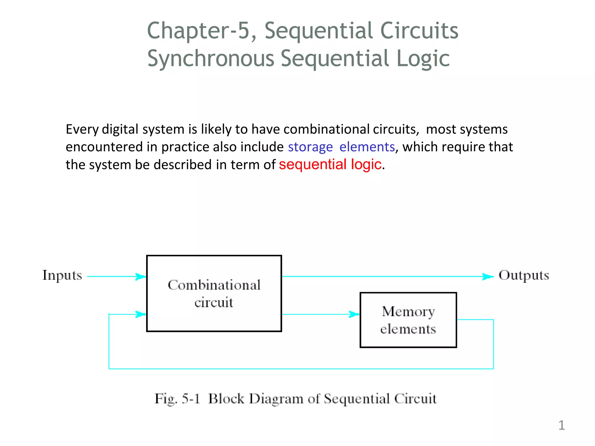
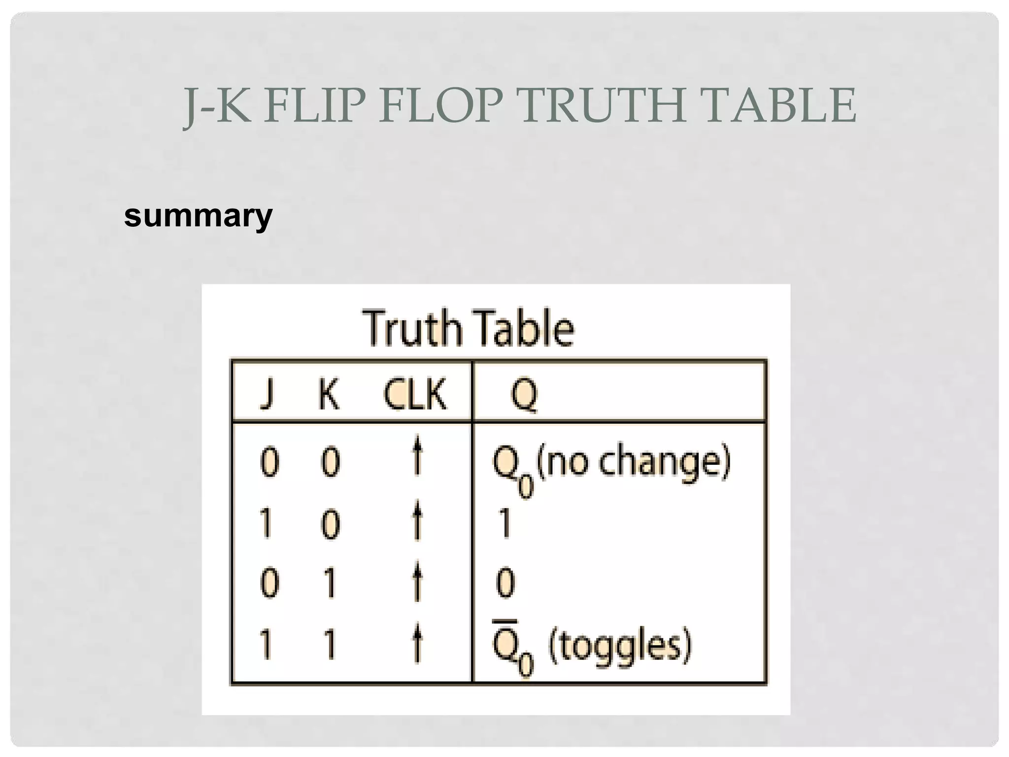
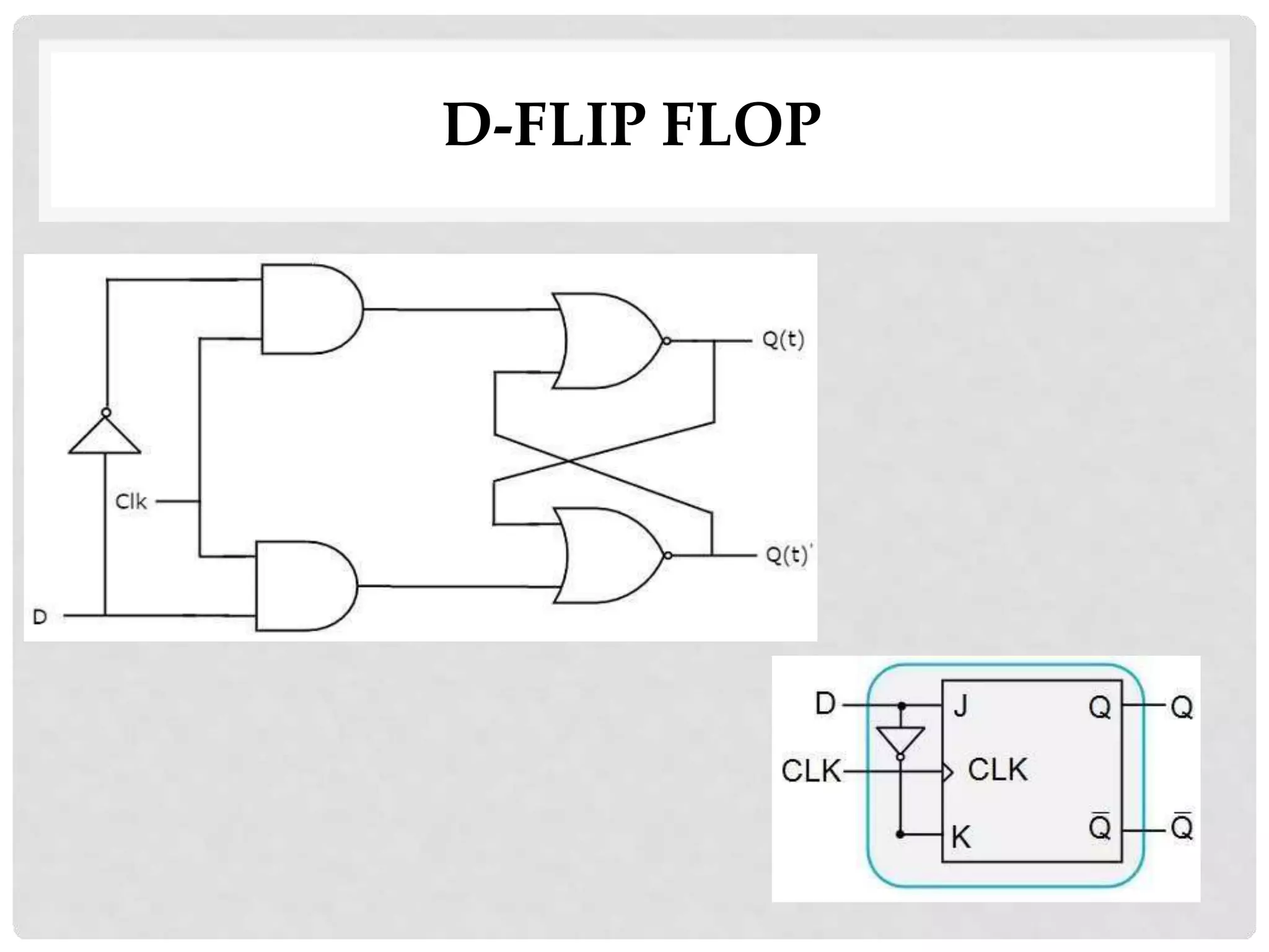
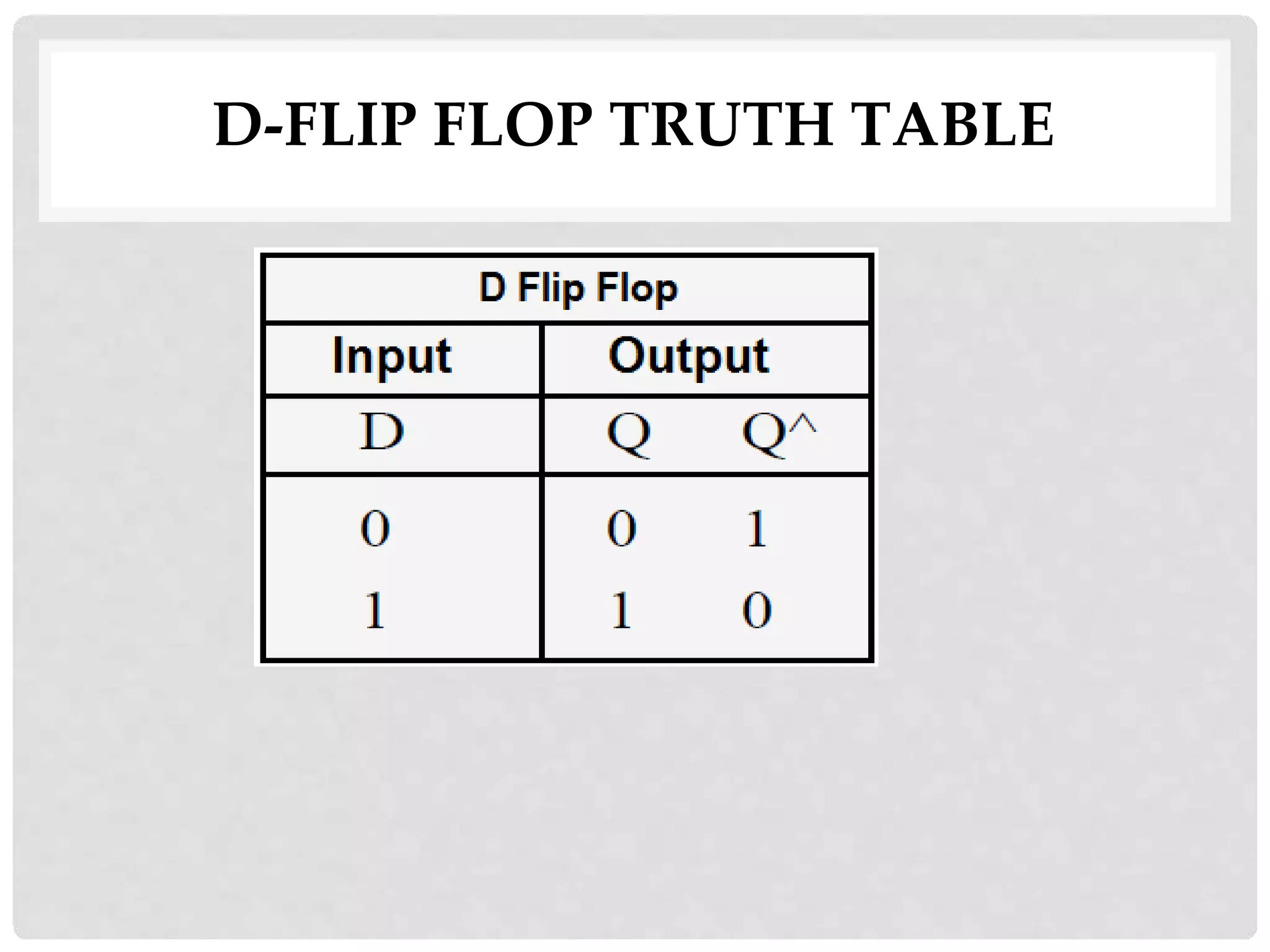
SlideShare a Scribd company logo
1 of 31
Download to read offline
Chapter-5, Sequential Circuits
Synchronous Sequential Logic
Every digital system is likely to have combinational circuits, most systems
encountered in practice also include storage elements, which require that
the system be described in term of sequential logic.
1
FLIP FLOPS
INTRODUCTION:
• Flip – flops have two stable states and hence they are
bistable multivibrators. The two stable states are High
(logic 1) and Low (logic 0).
• They can switch between the states under the influence of
a control signal (clock or enable) i.e. they can ‘flip’ to one
state and ‘flop’ back to other state.
• They are binary storage devices because they can store
binary data (0 or 1).
INTRODUCTION:
• They are also known as signal change sensitive
devices which mean that the change in the level of
clock signal will bring change in output of the flip
flop.
• A Flip – flop works depending on clock pulses.
• Flip flops are also used to control the digital
circuit’s functionality. They can change the
operation of a digital circuit depending on the state
CONVENTIONS
• The two outputs are complementary to each
other.
• If Q is 1 that is set Q’ to 0.
• If Q is 0, reset Q’ to 1. (Q and Q’ can’t be at the
same state simultaneously. If it happens, it will
violate the definition of the flip-flop and hence is
called undefined condition).
• Q is called the state of the flip-flop whereas Q’
is called complementary state of the flip-flop.
• When the output Q is either 0 or 1, it remains
in that state unless one or more inputs are
excited to effect the change on the output.
FLIP-FLOPS
TYPES of flip-flops
• RS FLIP FLOP
• D FLIP FLOP
• JK FLIP FLOP
• T FLIP FLOP
• pulse-triggered flip-flops: outputs response to
the triggering pulse
• edge-triggered flip-flops: outputs responses to
the control input edge
TYPESOF FLIPFLOPS
• S-RFlip-flop
• J-KFlip-flop
• D Flip-flop
• TFlip-flop
S-R FLIP FLOP
• The S-R flip-flop is basic flip-flop among all the flip-
flops.All the other flip flops are developed after SR-flip-
flop.
• SR flip flop is represented as shown below
S-R FLIP FLOP
• Any flip flop can be build using logic gates. NAND and NOR
gates were used as they are universal gates.
The Basic SR Flip-flop
The Basic SR Flip-flop with clock
JK-FLIP FLOP
• The J-K flip-flop is operationally similar to the S-
R flip-flop.
• The J-K flip-flop is clock driven like the clocked
S-R flip-flop.
• The difference is that the J-K flip-flop will retain
its output status when two lows are present at
its inputs. Also, when both inputs are high, the
outputs will toggle on and off
WORKING
• Q and Q' are feedback to the pulse-steering
NAND gates.
• No invalid state.
• Include a toggle (switch) state.
• J=HIGH (and K=LOW) - a SET state
• K=HIGH (and J=LOW) - a RESET state
• both inputs LOW - a no change
• both inputs HIGH - a toggle
• Toggling means ‘Changing the next state output to
complement of the present state output’
• Toggling will cause the output to complement
again and again.
• This complement operation continues until the
Clock pulse goes back to 0. Since this condition is
undesirable, we have to find a way to eliminate this
condition.
• This undesirable behavior can be eliminated by
Edge triggering of JK flip-flop or by using master
slave JK Flip-flops.
JK-FLIP FLOP
J-K FLIP FLOP TRUTH TABLE
summary
D-FLIP FLOP
The D flip-flop is widely used. It is also known as a
"data" or "delay" flip-flop and negative edge
triggered flip flop.
By comparing R-S, J-K, and D flip-flops one can
see that the D flip-flop never has an unknown
state, unlike the R-S and J-K.
• single input D (data)
• D=HIGH - a SET state
• D=LOW - a RESET state
D-FLIP FLOP
CLK D J K Q Q’
1 1 0 1 0 1
1 1 1 0 1 0
J=Q
D-FLIP FLOP TRUTH TABLE
T-FLIP FLOP
• AT flip flop is like JK flip-flop.
• These are basically a single input version of JK
flip flop.
• This modified form of JK flip-flop is obtained by
connecting both inputs J and K together.
•
• This flip-flop has only one input along with the
clock input.
clk T J K Q Q’ S R Q Q’
1 0 0 0 1 0 0 0 1 0 previous
values
0 1 0 0 0 1
1 1 1 1 1 0 0 1 0 1 compliment
of previous
values
0 1 1 0 1 0
TRIGGERING OF FLIP FLOPS
)> FLIP - FLOPS CHANGE STATE ONLY WHEN A CLOCK SIGNAL
IS PRESENT.
)> CLOCK SIGNAL ISNOT NECESSARILY INSTANTANEOUS SO THERE
NEEDS TO BE A WAY TO PREVENT THE FLIP-FLOP FROM
CHANGING STATE MULTIPLE TIMES DURING A CLOCK CYCLE.
)> 2 WAYS TO ACHIEVE THIS :
)> ONLY CHANGE STATE ONCE THE CLOCK CYCLE IS FINISHED.
THISTYPE OF FLIP-FLOP IS CALLED A MASTER -SLAVE FLIP-FLOP.
)> ONLY TRIGGERS DURING A SIGNAL TRANSITION. THIS TYPE IS
CALLED AN EDGE - TRIGGERED FLIP-FLOP.
MASTER - SLAVE FLIP – FLOPS
A pulse-triggered flip-flop consists of two latches, one acts
as a master and the other acts as a slave. Master-slave
flip-flop allows one flip-flop to change state as the clock
pulse is active.
Output from one flip-flop goes into another flip-flop,which is
attached to an inverted clock input. State of the first flip-flop
settles by the time its output changes the state of the second
flip-flop after the clock pulse has finished and stable outPut
is acheved.
EDGE TRIGGERED FLIP - FLOPS
5
);>- AN EDGE - TRIGGERED FLIP- FLOP IS A BISTABLE DEVICE
WHOSE STATE DEPENDS ON THE SYNCHRONOUS INPUTS
EITHER AT THE POSITIVE EDGE OR AT THE NEGATIVE
EDGE OF A CLOCK PULSE.
EDGE TRIGGERED FLIP -FLOPS TRIGGER ONLY WHEN THE
PULSE IS IN TRANSITION.
SOME TRIGGER DURING A POSITIVE TRANSITION ( 0 -TO - 1)
CALLED POSITIVE EDGE TRIGGERED FLIP - FLOPS. OTHERS
TRIGGER DURING A NEGATIVE TRANSITION ( 1-TO - 0 )
CALLED NEGATIVE EDGE TRIGGERED FLIP - FLOPS.
5-4 Analysis of Clocked Sequential Circuits
25
The analysis of a sequential circuit consists of
obtaining a table or a diagram for the time sequence of
inputs, outputs, and internal states. It is also possible to
write Boolean expressions that describe the behavior of
the sequential circuit. These expressions must include
the necessary time sequence, either directly or
indirectly.
State Equations
26
The behavior of a clocked sequential circuit can be
described algebraically by means of state equations. A state
equation specifies the next state as a function of the
present state and inputs.
State Equation
27
A(t+1) = A(t) x(t) + B(t) x(t)
B(t+1) = A`(t) x(t)
A state equation is an algebraic expression that specifies
the condition for a flip-flop state transition. The left side of
the equation with (t+1) denotes the next state of the flip-
flop one clock edge later. The right side of the equation is
Boolean expression that specifies the present state and
input conditions that make the next state equal to 1.
Y(t) = (A(t) + B(t)) x(t)`
State Table
The time sequence of inputs, outputs, and flip-flop states
can be enumerated in a state table (sometimes called
transition table).
28
State Diagram
The information available in a state table can be
represented graphically in the form of a state diagram. In
this type of diagram, a state is represented by a circle, and
the transitions between states are indicated by directed
lines connecting the circles.
1/0 : means input =1
output=0
29
Mealy and Moore Models (1)
•The most general model of a sequential circuit has inputs,
outputs, and internal states. It is customary to distinguish
between two models of sequential circuits:
the Mealy model and the Moore model
• They differ in the way the output is generated.
- In the Mealy model, the output is a function of both the
present state and input.
- In the Moore model, the output is a function of the present
state only.
30
Mealy and Moore Models (2)
31
When dealing with the two models, some books and other
technical sources refer to a sequential circuit as a finite state
machine abbreviated FSM.
- The Mealy model of a sequential circuit is referred to as a
Mealy FSM or Mealy machine.
-The Moore model is refereed to as a Moore FSM or Moore
machine.

More Related Content

What's hot (20)

Lec 07 - ANALYSIS OF CLOCKED SEQUENTIAL CIRCUITS
Lec 07 - ANALYSIS OF CLOCKED SEQUENTIAL CIRCUITSLec 07 - ANALYSIS OF CLOCKED SEQUENTIAL CIRCUITS
Lec 07 - ANALYSIS OF CLOCKED SEQUENTIAL CIRCUITS
 
Operators in java
Operators in javaOperators in java
Operators in java
 
Sequential circuits
Sequential circuitsSequential circuits
Sequential circuits
 
Flip flop
Flip flopFlip flop
Flip flop
 
Flip Flop
Flip FlopFlip Flop
Flip Flop
 
Counters
CountersCounters
Counters
 
Sequential logic circuits flip-flop pt 1
Sequential logic circuits   flip-flop pt 1Sequential logic circuits   flip-flop pt 1
Sequential logic circuits flip-flop pt 1
 
Latches & flip flop
Latches & flip flopLatches & flip flop
Latches & flip flop
 
Loops c++
Loops c++Loops c++
Loops c++
 
JK flip flop in Digital electronics
JK flip flop in Digital electronicsJK flip flop in Digital electronics
JK flip flop in Digital electronics
 
flip flop circuits and its applications
flip flop circuits and its applicationsflip flop circuits and its applications
flip flop circuits and its applications
 
2.3 sequantial logic circuit
2.3 sequantial logic circuit2.3 sequantial logic circuit
2.3 sequantial logic circuit
 
Flip Flop & RS Latch
Flip Flop & RS LatchFlip Flop & RS Latch
Flip Flop & RS Latch
 
D and T Flip Flop
D and T Flip FlopD and T Flip Flop
D and T Flip Flop
 
All flipflop
All flipflopAll flipflop
All flipflop
 
Sequential circuits
Sequential circuitsSequential circuits
Sequential circuits
 
Introduction to Counters
Introduction to CountersIntroduction to Counters
Introduction to Counters
 
latches
 latches latches
latches
 
While loop
While loopWhile loop
While loop
 
12 latches
12 latches12 latches
12 latches
 

Similar to DPCO UNIT 2.pdf

9flipflopsupdated-191016140658.pptx
9flipflopsupdated-191016140658.pptx9flipflopsupdated-191016140658.pptx
9flipflopsupdated-191016140658.pptxudhayaveenaa
 
Sequential logics 1
Sequential logics 1Sequential logics 1
Sequential logics 1faiqikhan
 
Sequential logics
Sequential logics Sequential logics
Sequential logics faiqikhan
 
Sequential logics
Sequential logicsSequential logics
Sequential logicsfaiqikhan
 
Sequential logics
Sequential logicsSequential logics
Sequential logicsfaiqikhan
 
Sequential logics
Sequential logicsSequential logics
Sequential logicsfaiqikhan
 
flip flop Presentation
flip flop  Presentationflip flop  Presentation
flip flop Presentationmaalik123
 
Flip Flop | Counters & Registers | Computer Fundamental and Organization
Flip Flop | Counters & Registers | Computer Fundamental and OrganizationFlip Flop | Counters & Registers | Computer Fundamental and Organization
Flip Flop | Counters & Registers | Computer Fundamental and OrganizationSmit Luvani
 
Sequential logic circuits flip-flop pt 3
Sequential logic circuits   flip-flop pt 3Sequential logic circuits   flip-flop pt 3
Sequential logic circuits flip-flop pt 3Sarah Sue Calbio
 
Sequential logic circuits flip-flop pt 3
Sequential logic circuits   flip-flop pt 3Sequential logic circuits   flip-flop pt 3
Sequential logic circuits flip-flop pt 3Sarah Sue Calbio
 
FYBSC IT Digital Electronics Unit IV Chapter II Sequential Circuits- Flip-Flops
FYBSC IT Digital Electronics Unit IV Chapter II Sequential Circuits- Flip-FlopsFYBSC IT Digital Electronics Unit IV Chapter II Sequential Circuits- Flip-Flops
FYBSC IT Digital Electronics Unit IV Chapter II Sequential Circuits- Flip-FlopsArti Parab Academics
 
SEQUENTIAL LOGIC CIRCUITS (FLIP FLOPS AND LATCHES)
SEQUENTIAL LOGIC CIRCUITS (FLIP FLOPS AND LATCHES)SEQUENTIAL LOGIC CIRCUITS (FLIP FLOPS AND LATCHES)
SEQUENTIAL LOGIC CIRCUITS (FLIP FLOPS AND LATCHES)Sairam Adithya
 
REPRESENTATION TO FLIP-FLOPS CHARACTERISTICS TABLE AND FLIP-FLOPS EXCITATION ...
REPRESENTATION TO FLIP-FLOPS CHARACTERISTICS TABLE AND FLIP-FLOPS EXCITATION ...REPRESENTATION TO FLIP-FLOPS CHARACTERISTICS TABLE AND FLIP-FLOPS EXCITATION ...
REPRESENTATION TO FLIP-FLOPS CHARACTERISTICS TABLE AND FLIP-FLOPS EXCITATION ...recoveraccount1
 
SEQUENTIAL CIRCUITS [FLIP FLOPS AND LATCHES]
SEQUENTIAL CIRCUITS [FLIP FLOPS AND LATCHES]SEQUENTIAL CIRCUITS [FLIP FLOPS AND LATCHES]
SEQUENTIAL CIRCUITS [FLIP FLOPS AND LATCHES]SUBHA SHREE
 
8.flip flops and registers
8.flip flops and registers8.flip flops and registers
8.flip flops and registersDeepak Sharma
 

Similar to DPCO UNIT 2.pdf (20)

9flipflopsupdated-191016140658.pptx
9flipflopsupdated-191016140658.pptx9flipflopsupdated-191016140658.pptx
9flipflopsupdated-191016140658.pptx
 
flip flops
flip flops flip flops
flip flops
 
Sequential logics 1
Sequential logics 1Sequential logics 1
Sequential logics 1
 
Sequential logics
Sequential logics Sequential logics
Sequential logics
 
Sequential logics
Sequential logicsSequential logics
Sequential logics
 
BE PPT (FLIP FLOPS)
BE PPT (FLIP FLOPS)BE PPT (FLIP FLOPS)
BE PPT (FLIP FLOPS)
 
Sequential logics
Sequential logicsSequential logics
Sequential logics
 
Sequential logics
Sequential logicsSequential logics
Sequential logics
 
flip flop Presentation
flip flop  Presentationflip flop  Presentation
flip flop Presentation
 
Flipflop
FlipflopFlipflop
Flipflop
 
Flip Flop | Counters & Registers | Computer Fundamental and Organization
Flip Flop | Counters & Registers | Computer Fundamental and OrganizationFlip Flop | Counters & Registers | Computer Fundamental and Organization
Flip Flop | Counters & Registers | Computer Fundamental and Organization
 
Sequential logic circuits flip-flop pt 3
Sequential logic circuits   flip-flop pt 3Sequential logic circuits   flip-flop pt 3
Sequential logic circuits flip-flop pt 3
 
Sequential logic circuits flip-flop pt 3
Sequential logic circuits   flip-flop pt 3Sequential logic circuits   flip-flop pt 3
Sequential logic circuits flip-flop pt 3
 
FYBSC IT Digital Electronics Unit IV Chapter II Sequential Circuits- Flip-Flops
FYBSC IT Digital Electronics Unit IV Chapter II Sequential Circuits- Flip-FlopsFYBSC IT Digital Electronics Unit IV Chapter II Sequential Circuits- Flip-Flops
FYBSC IT Digital Electronics Unit IV Chapter II Sequential Circuits- Flip-Flops
 
SEQUENTIAL LOGIC CIRCUITS (FLIP FLOPS AND LATCHES)
SEQUENTIAL LOGIC CIRCUITS (FLIP FLOPS AND LATCHES)SEQUENTIAL LOGIC CIRCUITS (FLIP FLOPS AND LATCHES)
SEQUENTIAL LOGIC CIRCUITS (FLIP FLOPS AND LATCHES)
 
Presentation1
Presentation1Presentation1
Presentation1
 
REPRESENTATION TO FLIP-FLOPS CHARACTERISTICS TABLE AND FLIP-FLOPS EXCITATION ...
REPRESENTATION TO FLIP-FLOPS CHARACTERISTICS TABLE AND FLIP-FLOPS EXCITATION ...REPRESENTATION TO FLIP-FLOPS CHARACTERISTICS TABLE AND FLIP-FLOPS EXCITATION ...
REPRESENTATION TO FLIP-FLOPS CHARACTERISTICS TABLE AND FLIP-FLOPS EXCITATION ...
 
SEQUENTIAL CIRCUITS [Flip-flops and Latches]
SEQUENTIAL CIRCUITS [Flip-flops and Latches]SEQUENTIAL CIRCUITS [Flip-flops and Latches]
SEQUENTIAL CIRCUITS [Flip-flops and Latches]
 
SEQUENTIAL CIRCUITS [FLIP FLOPS AND LATCHES]
SEQUENTIAL CIRCUITS [FLIP FLOPS AND LATCHES]SEQUENTIAL CIRCUITS [FLIP FLOPS AND LATCHES]
SEQUENTIAL CIRCUITS [FLIP FLOPS AND LATCHES]
 
8.flip flops and registers
8.flip flops and registers8.flip flops and registers
8.flip flops and registers
 

Recently uploaded

Alper Gobel In Media Res Media Component
Alper Gobel In Media Res Media ComponentAlper Gobel In Media Res Media Component
Alper Gobel In Media Res Media ComponentInMediaRes1
 
Keynote by Prof. Wurzer at Nordex about IP-design
Keynote by Prof. Wurzer at Nordex about IP-designKeynote by Prof. Wurzer at Nordex about IP-design
Keynote by Prof. Wurzer at Nordex about IP-designMIPLM
 
Romantic Opera MUSIC FOR GRADE NINE pptx
Romantic Opera MUSIC FOR GRADE NINE pptxRomantic Opera MUSIC FOR GRADE NINE pptx
Romantic Opera MUSIC FOR GRADE NINE pptxsqpmdrvczh
 
Earth Day Presentation wow hello nice great
Earth Day Presentation wow hello nice greatEarth Day Presentation wow hello nice great
Earth Day Presentation wow hello nice greatYousafMalik24
 
Full Stack Web Development Course for Beginners
Full Stack Web Development Course  for BeginnersFull Stack Web Development Course  for Beginners
Full Stack Web Development Course for BeginnersSabitha Banu
 
Introduction to AI in Higher Education_draft.pptx
Introduction to AI in Higher Education_draft.pptxIntroduction to AI in Higher Education_draft.pptx
Introduction to AI in Higher Education_draft.pptxpboyjonauth
 
How to Configure Email Server in Odoo 17
How to Configure Email Server in Odoo 17How to Configure Email Server in Odoo 17
How to Configure Email Server in Odoo 17Celine George
 
Solving Puzzles Benefits Everyone (English).pptx
Solving Puzzles Benefits Everyone (English).pptxSolving Puzzles Benefits Everyone (English).pptx
Solving Puzzles Benefits Everyone (English).pptxOH TEIK BIN
 
How to do quick user assign in kanban in Odoo 17 ERP
How to do quick user assign in kanban in Odoo 17 ERPHow to do quick user assign in kanban in Odoo 17 ERP
How to do quick user assign in kanban in Odoo 17 ERPCeline George
 
EPANDING THE CONTENT OF AN OUTLINE using notes.pptx
EPANDING THE CONTENT OF AN OUTLINE using notes.pptxEPANDING THE CONTENT OF AN OUTLINE using notes.pptx
EPANDING THE CONTENT OF AN OUTLINE using notes.pptxRaymartEstabillo3
 
Quarter 4 Peace-education.pptx Catch Up Friday
Quarter 4 Peace-education.pptx Catch Up FridayQuarter 4 Peace-education.pptx Catch Up Friday
Quarter 4 Peace-education.pptx Catch Up FridayMakMakNepo
 
Judging the Relevance and worth of ideas part 2.pptx
Judging the Relevance  and worth of ideas part 2.pptxJudging the Relevance  and worth of ideas part 2.pptx
Judging the Relevance and worth of ideas part 2.pptxSherlyMaeNeri
 
AMERICAN LANGUAGE HUB_Level2_Student'sBook_Answerkey.pdf
AMERICAN LANGUAGE HUB_Level2_Student'sBook_Answerkey.pdfAMERICAN LANGUAGE HUB_Level2_Student'sBook_Answerkey.pdf
AMERICAN LANGUAGE HUB_Level2_Student'sBook_Answerkey.pdfphamnguyenenglishnb
 
AmericanHighSchoolsprezentacijaoskolama.
AmericanHighSchoolsprezentacijaoskolama.AmericanHighSchoolsprezentacijaoskolama.
AmericanHighSchoolsprezentacijaoskolama.arsicmarija21
 
ECONOMIC CONTEXT - LONG FORM TV DRAMA - PPT
ECONOMIC CONTEXT - LONG FORM TV DRAMA - PPTECONOMIC CONTEXT - LONG FORM TV DRAMA - PPT
ECONOMIC CONTEXT - LONG FORM TV DRAMA - PPTiammrhaywood
 
Planning a health career 4th Quarter.pptx
Planning a health career 4th Quarter.pptxPlanning a health career 4th Quarter.pptx
Planning a health career 4th Quarter.pptxLigayaBacuel1
 

Recently uploaded (20)

Alper Gobel In Media Res Media Component
Alper Gobel In Media Res Media ComponentAlper Gobel In Media Res Media Component
Alper Gobel In Media Res Media Component
 
Keynote by Prof. Wurzer at Nordex about IP-design
Keynote by Prof. Wurzer at Nordex about IP-designKeynote by Prof. Wurzer at Nordex about IP-design
Keynote by Prof. Wurzer at Nordex about IP-design
 
Romantic Opera MUSIC FOR GRADE NINE pptx
Romantic Opera MUSIC FOR GRADE NINE pptxRomantic Opera MUSIC FOR GRADE NINE pptx
Romantic Opera MUSIC FOR GRADE NINE pptx
 
Earth Day Presentation wow hello nice great
Earth Day Presentation wow hello nice greatEarth Day Presentation wow hello nice great
Earth Day Presentation wow hello nice great
 
Full Stack Web Development Course for Beginners
Full Stack Web Development Course  for BeginnersFull Stack Web Development Course  for Beginners
Full Stack Web Development Course for Beginners
 
9953330565 Low Rate Call Girls In Rohini Delhi NCR
9953330565 Low Rate Call Girls In Rohini  Delhi NCR9953330565 Low Rate Call Girls In Rohini  Delhi NCR
9953330565 Low Rate Call Girls In Rohini Delhi NCR
 
OS-operating systems- ch04 (Threads) ...
OS-operating systems- ch04 (Threads) ...OS-operating systems- ch04 (Threads) ...
OS-operating systems- ch04 (Threads) ...
 
TataKelola dan KamSiber Kecerdasan Buatan v022.pdf
TataKelola dan KamSiber Kecerdasan Buatan v022.pdfTataKelola dan KamSiber Kecerdasan Buatan v022.pdf
TataKelola dan KamSiber Kecerdasan Buatan v022.pdf
 
Introduction to AI in Higher Education_draft.pptx
Introduction to AI in Higher Education_draft.pptxIntroduction to AI in Higher Education_draft.pptx
Introduction to AI in Higher Education_draft.pptx
 
How to Configure Email Server in Odoo 17
How to Configure Email Server in Odoo 17How to Configure Email Server in Odoo 17
How to Configure Email Server in Odoo 17
 
Solving Puzzles Benefits Everyone (English).pptx
Solving Puzzles Benefits Everyone (English).pptxSolving Puzzles Benefits Everyone (English).pptx
Solving Puzzles Benefits Everyone (English).pptx
 
How to do quick user assign in kanban in Odoo 17 ERP
How to do quick user assign in kanban in Odoo 17 ERPHow to do quick user assign in kanban in Odoo 17 ERP
How to do quick user assign in kanban in Odoo 17 ERP
 
EPANDING THE CONTENT OF AN OUTLINE using notes.pptx
EPANDING THE CONTENT OF AN OUTLINE using notes.pptxEPANDING THE CONTENT OF AN OUTLINE using notes.pptx
EPANDING THE CONTENT OF AN OUTLINE using notes.pptx
 
Quarter 4 Peace-education.pptx Catch Up Friday
Quarter 4 Peace-education.pptx Catch Up FridayQuarter 4 Peace-education.pptx Catch Up Friday
Quarter 4 Peace-education.pptx Catch Up Friday
 
Judging the Relevance and worth of ideas part 2.pptx
Judging the Relevance  and worth of ideas part 2.pptxJudging the Relevance  and worth of ideas part 2.pptx
Judging the Relevance and worth of ideas part 2.pptx
 
AMERICAN LANGUAGE HUB_Level2_Student'sBook_Answerkey.pdf
AMERICAN LANGUAGE HUB_Level2_Student'sBook_Answerkey.pdfAMERICAN LANGUAGE HUB_Level2_Student'sBook_Answerkey.pdf
AMERICAN LANGUAGE HUB_Level2_Student'sBook_Answerkey.pdf
 
Model Call Girl in Tilak Nagar Delhi reach out to us at 🔝9953056974🔝
Model Call Girl in Tilak Nagar Delhi reach out to us at 🔝9953056974🔝Model Call Girl in Tilak Nagar Delhi reach out to us at 🔝9953056974🔝
Model Call Girl in Tilak Nagar Delhi reach out to us at 🔝9953056974🔝
 
AmericanHighSchoolsprezentacijaoskolama.
AmericanHighSchoolsprezentacijaoskolama.AmericanHighSchoolsprezentacijaoskolama.
AmericanHighSchoolsprezentacijaoskolama.
 
ECONOMIC CONTEXT - LONG FORM TV DRAMA - PPT
ECONOMIC CONTEXT - LONG FORM TV DRAMA - PPTECONOMIC CONTEXT - LONG FORM TV DRAMA - PPT
ECONOMIC CONTEXT - LONG FORM TV DRAMA - PPT
 
Planning a health career 4th Quarter.pptx
Planning a health career 4th Quarter.pptxPlanning a health career 4th Quarter.pptx
Planning a health career 4th Quarter.pptx
 

DPCO UNIT 2.pdf

  • 1. Chapter-5, Sequential Circuits Synchronous Sequential Logic Every digital system is likely to have combinational circuits, most systems encountered in practice also include storage elements, which require that the system be described in term of sequential logic. 1
  • 3. INTRODUCTION: • Flip – flops have two stable states and hence they are bistable multivibrators. The two stable states are High (logic 1) and Low (logic 0). • They can switch between the states under the influence of a control signal (clock or enable) i.e. they can ‘flip’ to one state and ‘flop’ back to other state. • They are binary storage devices because they can store binary data (0 or 1).
  • 4. INTRODUCTION: • They are also known as signal change sensitive devices which mean that the change in the level of clock signal will bring change in output of the flip flop. • A Flip – flop works depending on clock pulses. • Flip flops are also used to control the digital circuit’s functionality. They can change the operation of a digital circuit depending on the state
  • 5. CONVENTIONS • The two outputs are complementary to each other. • If Q is 1 that is set Q’ to 0. • If Q is 0, reset Q’ to 1. (Q and Q’ can’t be at the same state simultaneously. If it happens, it will violate the definition of the flip-flop and hence is called undefined condition).
  • 6. • Q is called the state of the flip-flop whereas Q’ is called complementary state of the flip-flop. • When the output Q is either 0 or 1, it remains in that state unless one or more inputs are excited to effect the change on the output.
  • 7. FLIP-FLOPS TYPES of flip-flops • RS FLIP FLOP • D FLIP FLOP • JK FLIP FLOP • T FLIP FLOP • pulse-triggered flip-flops: outputs response to the triggering pulse • edge-triggered flip-flops: outputs responses to the control input edge
  • 8. TYPESOF FLIPFLOPS • S-RFlip-flop • J-KFlip-flop • D Flip-flop • TFlip-flop
  • 9. S-R FLIP FLOP • The S-R flip-flop is basic flip-flop among all the flip- flops.All the other flip flops are developed after SR-flip- flop. • SR flip flop is represented as shown below
  • 10. S-R FLIP FLOP • Any flip flop can be build using logic gates. NAND and NOR gates were used as they are universal gates.
  • 11. The Basic SR Flip-flop The Basic SR Flip-flop with clock
  • 12. JK-FLIP FLOP • The J-K flip-flop is operationally similar to the S- R flip-flop. • The J-K flip-flop is clock driven like the clocked S-R flip-flop. • The difference is that the J-K flip-flop will retain its output status when two lows are present at its inputs. Also, when both inputs are high, the outputs will toggle on and off
  • 13. WORKING • Q and Q' are feedback to the pulse-steering NAND gates. • No invalid state. • Include a toggle (switch) state. • J=HIGH (and K=LOW) - a SET state • K=HIGH (and J=LOW) - a RESET state • both inputs LOW - a no change • both inputs HIGH - a toggle
  • 14. • Toggling means ‘Changing the next state output to complement of the present state output’ • Toggling will cause the output to complement again and again. • This complement operation continues until the Clock pulse goes back to 0. Since this condition is undesirable, we have to find a way to eliminate this condition. • This undesirable behavior can be eliminated by Edge triggering of JK flip-flop or by using master slave JK Flip-flops.
  • 16. J-K FLIP FLOP TRUTH TABLE summary
  • 17. D-FLIP FLOP The D flip-flop is widely used. It is also known as a "data" or "delay" flip-flop and negative edge triggered flip flop. By comparing R-S, J-K, and D flip-flops one can see that the D flip-flop never has an unknown state, unlike the R-S and J-K. • single input D (data) • D=HIGH - a SET state • D=LOW - a RESET state
  • 19. CLK D J K Q Q’ 1 1 0 1 0 1 1 1 1 0 1 0 J=Q D-FLIP FLOP TRUTH TABLE
  • 20. T-FLIP FLOP • AT flip flop is like JK flip-flop. • These are basically a single input version of JK flip flop. • This modified form of JK flip-flop is obtained by connecting both inputs J and K together. • • This flip-flop has only one input along with the clock input.
  • 21. clk T J K Q Q’ S R Q Q’ 1 0 0 0 1 0 0 0 1 0 previous values 0 1 0 0 0 1 1 1 1 1 1 0 0 1 0 1 compliment of previous values 0 1 1 0 1 0
  • 22. TRIGGERING OF FLIP FLOPS )> FLIP - FLOPS CHANGE STATE ONLY WHEN A CLOCK SIGNAL IS PRESENT. )> CLOCK SIGNAL ISNOT NECESSARILY INSTANTANEOUS SO THERE NEEDS TO BE A WAY TO PREVENT THE FLIP-FLOP FROM CHANGING STATE MULTIPLE TIMES DURING A CLOCK CYCLE. )> 2 WAYS TO ACHIEVE THIS : )> ONLY CHANGE STATE ONCE THE CLOCK CYCLE IS FINISHED. THISTYPE OF FLIP-FLOP IS CALLED A MASTER -SLAVE FLIP-FLOP. )> ONLY TRIGGERS DURING A SIGNAL TRANSITION. THIS TYPE IS CALLED AN EDGE - TRIGGERED FLIP-FLOP.
  • 23. MASTER - SLAVE FLIP – FLOPS A pulse-triggered flip-flop consists of two latches, one acts as a master and the other acts as a slave. Master-slave flip-flop allows one flip-flop to change state as the clock pulse is active. Output from one flip-flop goes into another flip-flop,which is attached to an inverted clock input. State of the first flip-flop settles by the time its output changes the state of the second flip-flop after the clock pulse has finished and stable outPut is acheved.
  • 24. EDGE TRIGGERED FLIP - FLOPS 5 );>- AN EDGE - TRIGGERED FLIP- FLOP IS A BISTABLE DEVICE WHOSE STATE DEPENDS ON THE SYNCHRONOUS INPUTS EITHER AT THE POSITIVE EDGE OR AT THE NEGATIVE EDGE OF A CLOCK PULSE. EDGE TRIGGERED FLIP -FLOPS TRIGGER ONLY WHEN THE PULSE IS IN TRANSITION. SOME TRIGGER DURING A POSITIVE TRANSITION ( 0 -TO - 1) CALLED POSITIVE EDGE TRIGGERED FLIP - FLOPS. OTHERS TRIGGER DURING A NEGATIVE TRANSITION ( 1-TO - 0 ) CALLED NEGATIVE EDGE TRIGGERED FLIP - FLOPS.
  • 25. 5-4 Analysis of Clocked Sequential Circuits 25 The analysis of a sequential circuit consists of obtaining a table or a diagram for the time sequence of inputs, outputs, and internal states. It is also possible to write Boolean expressions that describe the behavior of the sequential circuit. These expressions must include the necessary time sequence, either directly or indirectly.
  • 26. State Equations 26 The behavior of a clocked sequential circuit can be described algebraically by means of state equations. A state equation specifies the next state as a function of the present state and inputs.
  • 27. State Equation 27 A(t+1) = A(t) x(t) + B(t) x(t) B(t+1) = A`(t) x(t) A state equation is an algebraic expression that specifies the condition for a flip-flop state transition. The left side of the equation with (t+1) denotes the next state of the flip- flop one clock edge later. The right side of the equation is Boolean expression that specifies the present state and input conditions that make the next state equal to 1. Y(t) = (A(t) + B(t)) x(t)`
  • 28. State Table The time sequence of inputs, outputs, and flip-flop states can be enumerated in a state table (sometimes called transition table). 28
  • 29. State Diagram The information available in a state table can be represented graphically in the form of a state diagram. In this type of diagram, a state is represented by a circle, and the transitions between states are indicated by directed lines connecting the circles. 1/0 : means input =1 output=0 29
  • 30. Mealy and Moore Models (1) •The most general model of a sequential circuit has inputs, outputs, and internal states. It is customary to distinguish between two models of sequential circuits: the Mealy model and the Moore model • They differ in the way the output is generated. - In the Mealy model, the output is a function of both the present state and input. - In the Moore model, the output is a function of the present state only. 30
  • 31. Mealy and Moore Models (2) 31 When dealing with the two models, some books and other technical sources refer to a sequential circuit as a finite state machine abbreviated FSM. - The Mealy model of a sequential circuit is referred to as a Mealy FSM or Mealy machine. -The Moore model is refereed to as a Moore FSM or Moore machine.