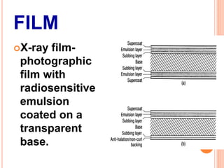
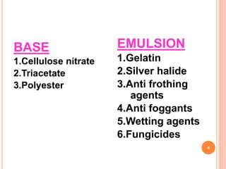
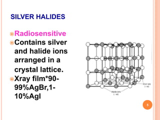
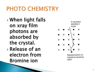
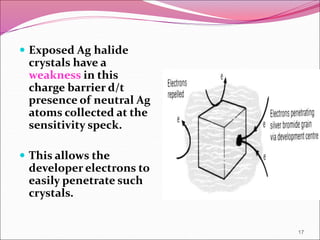
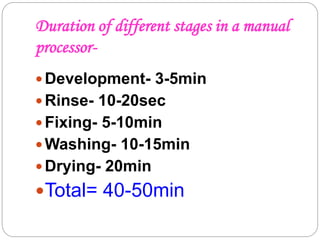
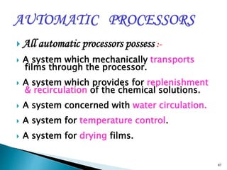
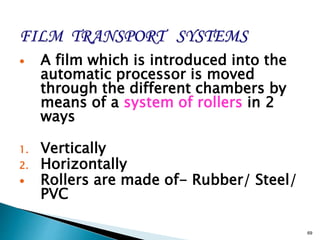
This document provides information on the process of film development. It discusses the components of x-ray film, including the silver halide crystals and sensitivity specks that form the latent image. It describes the chemical and light-induced processes that create this invisible image. The stages of film processing are outlined, including development, rinsing, fixing, washing and drying. Details are given on the chemical constituents and functions of developers, stop baths, fixers and other processing solutions. Factors that influence development such as temperature, time and chemical concentrations are also summarized.


![Xray film types and construction [Autosaved].pptx](https://cdn.slidesharecdn.com/ss_thumbnails/xrayfilmtypesandconstructionautosaved-240526175237-7ce35e4e-thumbnail.jpg?width=640&height=640&fit=bounds)


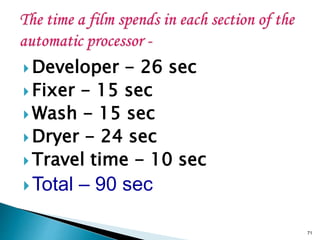
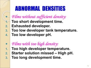
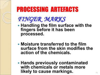
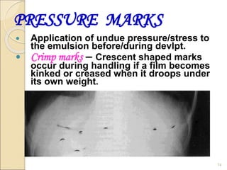
![X-RAY FILM PROCESSING [Autosavee/d].pptx](https://cdn.slidesharecdn.com/ss_thumbnails/x-rayfilmprocessingautosaved-240224053318-4459007d-thumbnail.jpg?width=640&height=640&fit=bounds)


