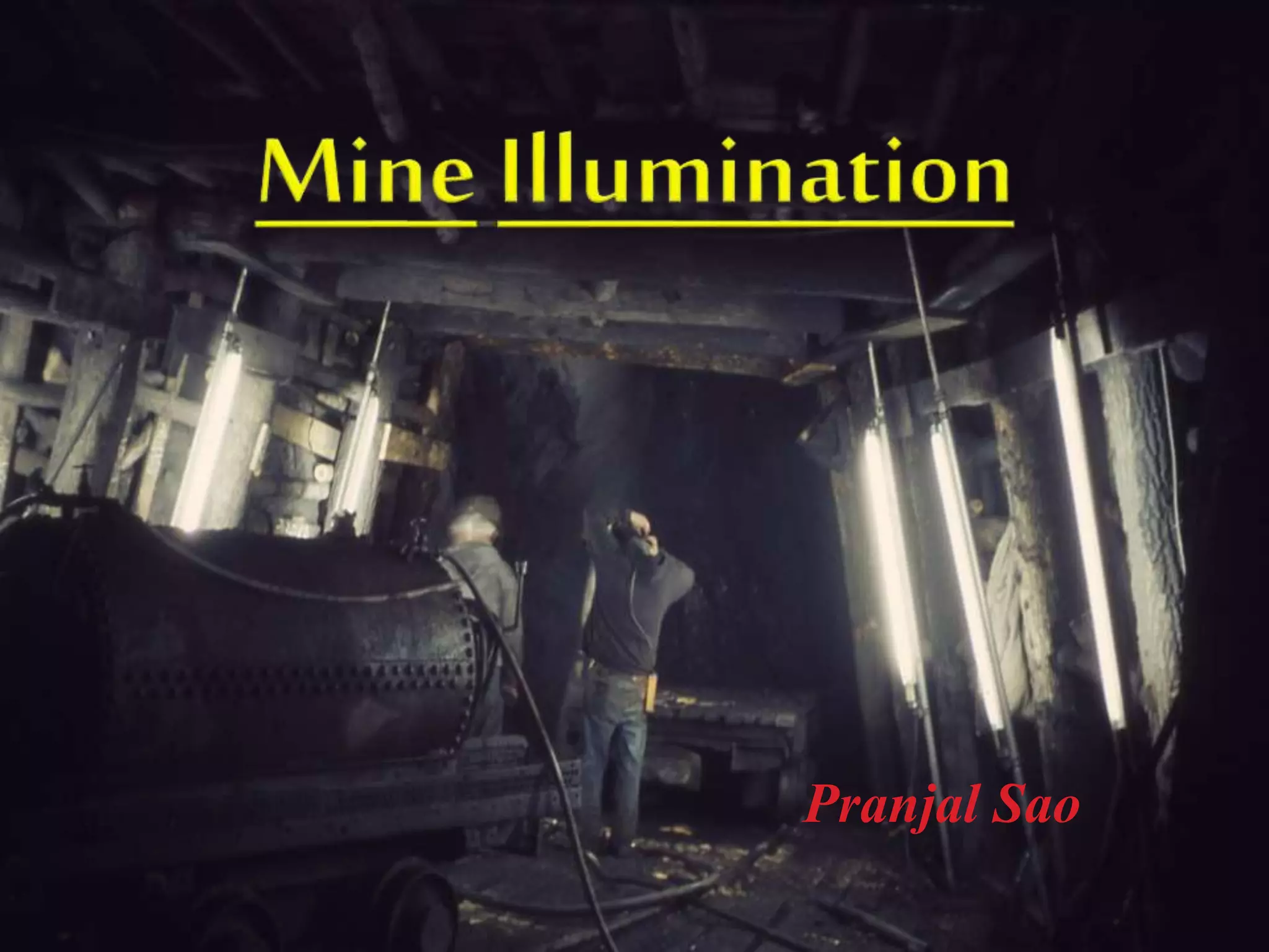
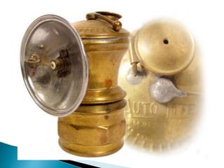
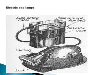
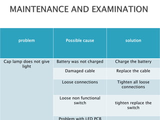
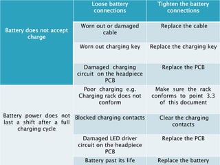
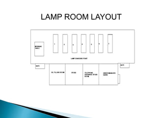
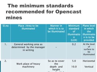
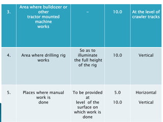
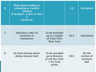
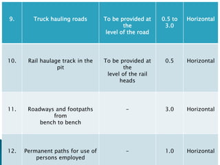
Pranjal Sao
Mining…“the most difficult lighting
environment in the world”
Illumination Engineering Society of North America,
2003.
Provision of suitable work
environment for the workers is essential for
achieving higher production and productivity in
both surface and underground mines. Poor
lighting working conditions have negative effects
on the workers’ morale and adversely affects
their safety, health and performance.
In order to assess the status
of illumination levels in mines, systematic
illumination surveys are needed to be conducted
using appropriate statutory guidelines so that
effective control measures can be taken up in
mines.
Light Physics
Two major systems of units are currently used for
the quantification of light-
1) illumination Engineering society (IES)
2)international systems of units (SI)
All standard systems of light units employ
certain fundamental concepts
These basic concepts are luminous flux,
illumination, luminous intensity, and luminance.
 Intensity of light:
it is the relative amount of luminous energy given by
an source and is measured in candles or candle
power or in candelas (in CGS unit).
 Mean horizontal candle power:
it is the average candle power of a lamp in all
directions in a horizontal plane passing through the
center of the sources and is usually obtained by
rotating the lamp about a vertical axis.
 Mean spherical candle power:
it is the average candle power of a lamp in all
directions, or the candle power of a uniform source
giving the same total flux of light. It is directly
proportional to the total light given by the lamp and is
measured by taking intensity readings in all
directions.
 Luminous flux:
The luminous flux symbol is Ø, and the lumen (lm)
is the flux unit n used in both the IES and SI
systems. Luminous flux is the time flow rate of light
energy. Flux is a power quantity in the same manner
as horsepower. The unit of luminous flux, the
lumen, is most frequently used to describe the
lighting power of light sources.
 Lumen (unit):
The lumen (symbol: lm) is the SI unit of
luminous flux, a measure of the perceived power
of light. Luminous flux differs from radiant flux, the
measure of the total power of light emitted, in that
luminous flux is adjusted to reflect the varying
sensitivity o f the human eye to different
wavelengths of light.
 Illuminance:
Illuminance is the amount of light falling on a
surface. The unit of measurement is lux (lx) and
2 lumen /min the SI system (or lumens per square
meter = 10.76 foot candles, fc). A light meter is
used to measure it. Readings are taken from several
angles and positions.
 Luminance:
Luminance is the amount of light reflected
from a surface. The unit of measurement is
candela per square meter (equals 0.29 foot-
lamberts). An illuminance meter is used to measure
it. Several measurements are made and averaged.
Luminance tables are consulted for reference
values.
 Reflectance:
This is the ratio of reflected luminous flux to
incident luminous flux. In other words, the ratio of
light energy reflected from a surface to the
amount striking it. Objects with higher levels of
reflectance will appear brighter than those of
lower reflectance under the same lighting
conditions
Contrast
The relative difference in luminance between two
adjacent surfaces.
In other words, how bright one surface looks
compared to the other or the background against
which it is being viewed.
Uniformity Ratio
This may be expressed as a ratio of average
to minimum or it may be expressed as a ratio
of maximum to minimum level of illumination
for a given area.

Surface Reflectance percentage(%)
Coal 3-15
Calcite stone dust 59
Dolomite stone dust 09
Rust 09
Fresh white wash 65-95
Faded white wash 20-60
General lighting arrangements have to be
provided in a mine at the following places and if
electricity is available the lights should be electric.
(a) On the surface at the pit top/incline top and
in every engine room if natural light is insufficient.
(b) Below ground:
 At every shaft inset and shaft bottom or siding
which is in regular use;
 In every travelling roadway normally used by 50 or
more person during any shift;
 At the top and bottom of every self-acting incline in
regular use;
 At every place on a haulage roadway, at which
tubs are regularly coupled or uncoupled from
haulage rope;
 At every place at which tubs are regularly filled
mechanically;
 At every room and place containing any engine,
motor or other apparatus;
 At every place where any pillar is under ex
traction;
 At every first aid station below ground;
Every lighting fitting in underground coal mine has to
be of flame proof design.
1. Acetylene portable hand
lamp:
 A commonly used portable lamp in
metal mines is the acetylene hand
lamp.
 It is also known as carbide lamp.
 These are simple lamps that produce and burn
acetylene (C2H2) which is created by the
reaction of calcium carbide (CaC2) with water.
 The conventional format of producing acetylene
in a lamp is by putting the calcium carbide in the
lower chamber (the generator).
 The upper reservoir is then filled with water.
 A threaded valve or other mechanism is used to
control the rate at which the water is allowed to
drip onto the chamber containing the calcium
carbide.
 By controlling the rate of water flow, the production
of acetylene gas is controlled.
 This, in turn, controls the flow rate of the gas and
the size of the flame at the burner, (and thus the
amount of light it produces).
 This type of lamp generally has a reflector behind
the flame to help project the light forward.
 An Acetylene Gas powered lamp produces a
surprisingly bright, broad light
 . This type of unfocused light works well
underground as it improves peripheral
vision in the complete dark.
 The reaction of carbide with water
produces a fair amount of heat
independent of the flame.
 In a cold mine a carbide lamp can be used
by a miner to provide a heat to help
prevent hypothermia.
 The first carbide lamp (mining lamp)
developed in the United States was
patented in New York on August 28, 1900
by Frederick Baldwin.
2.Flameproof safety torch:
 Safety torches intrinsically safe in inflammable
atmosphere.
 The torch is locked in the lamp cabin and can be
opened only by special tools. Unlocking and
opening in a mine is impossible.
 The glass at the mouthpiece is toughened acrylic
disc(unbreakable type).
 The glass is protected by a grill of 2mm wide
brassplates in the mouthpiece.
 The bulb is protected by a spring placed over.
 If the glass breaks, the spring is thrown out and
the bulb loses its contact with the battery terminal
thereby ceasing to burn.
 Exposure of the hot filament of the bulb in case of
breakage of the latter is out of question.
 There is a spring cushion, a sort of shock
absorber, between the bulb and dry cell which
prevent crushing of the bulb against the weight of
the dry cells in case of accidental dropping of the
torch.
3.Electric cap lamps:
 The electric cap lamps used in our mines are the
popularly known Oldham cap lamps and also the
cap lamps manufactured by mines safety
appliances Co. ltd.
 In cap lamps the entire cap lamp unit consists of a
4-v lead acid battery (re-chargeable type)
 A lamp which can be hooked to the helmet and a
connecting cable. The lead acid battery consists of
two cells.
 In the Oldham cap lamp unit each cell of the lead
acid battery consists of a number of composite
lead antimony tubes or plates.
 Plates carrying the active materials and immersed
in a 30% of sulphuric acid and distilled water.
 The positive plate in each cell is of pasted flat
type, and the insulating separators are of sponac (
a highly absorbant type of wood) which absorbs
about 85% of the total acid in the cell.
 In the fully charged condition, the active material
in the positive plates in brown lead
peroxide(PbO2) and in the negative plates, it is
grey spongy lead (Pb).
 During discharge, both positive and negative
plates change partly into lead sulphate ,with
liberation of water. During discharge, negative
plates ,it is grey spongy lead.
 The following reaction takes place during
charging, it is reversible reaction, during
discharging-
PbO2 + 2H2SO4+ Pb = PbSO4 + 2H2O +
PbSO4
problem Possible cause solution
Cap lamp does not give
light
Battery was not charged Charge the battery
Damaged cable Replace the cable
Loose connections Tighten all loose
connections
Loose non functional
switch tighten replace the
switch
Battery does not accept
charge
Loose battery
connections
Tighten the battery
connections
Worn out or damaged
cable
Replace the cable
Worn out charging key Replace the charging key
Damaged charging
circuit on the headpiece
PCB
Replace the PCB
Battery power does not
last a shift after a full
charging cycle
Poor charging e.g.
Charging rack does not
conform
Make sure the rack
conforms to point 3.3
of this document
Blocked charging contacts Clear the charging
contacts
Damaged LED driver
circuit on the headpiece
PCB
Replace the PCB
Battery past its life Replace the battery
LAMP ROOM LAYOUT
 It is situated at the surface .
 In this room batteries of the cap lamp are charged.
 The batteries are of 4 volts.
 These batteries are of lead acid battery
rechargeable type.
 The nominal voltage of led acid cell is of 2 volt so
that two cell must be connected in series to give 4
volt.
 Following reaction takes place in the cell:-
Pbo2 + 2H2SO4 + Pb =PbSo4 + 2H2O +PbSO4
 5-6 volt D.C. power is required to charge the
battery, but 4.8 volt is the stander.
 The light provided by the flame safety lamp and
electric cap lamp is inadequate for general lighting
and proper illumination in ug mines.
 Electric lamp should therefore be used for general
lighting and at places where more illumination is
required.
 When providing for general lighting car should be
taken to that workers should not have to face tha
glare of the lamps.
 Deep shadows are not cast by the lights and there
is sufficient illumination.
 An illumination on 20 to 40 lumens per m2 at the
pit bottom.
 15to 20 lumens per m2 at haulage junction is
considered adequate.
 Use of lamps of high candle power, but low
intrinsic brightness.
 By closure spacing.
 By white washing the area.
 Power can be used at voltage exceeding 110
volts.
 Lights at 220/250 volts cannot be used.
 Lighting transformers should provide the voltage
by stepping down form the usual 550/440 or 3300
volts and neutral point of the secondary
transformer should be earthen.
 All lights and light fittings should be in flame proof
enclosure.
 There are only 2 or 3 well known companies in
India, who manufacture such flameproof light
enclosure.
 It is not clearly laid down in the electricity rules it is
advisable not to use electric lights from mains at
or within a distance of 100 m from a longwall coal
face from emmision of firedamp.
 Electric light can be used in the main return of
gassy mine degree 2 and 3, if the lighting fittings
are flame proof.
 Electric discharge lamp.
 Fluorescent tubes for mine lighting.
 At atmospheric and higher pressure the resistivity
of gas is very high and a breakdown of this
resistivity by a sufficiently high voltage causes
spark or arc.
 If the pressure of gas in a closed space is reduced
to a very low value not only is the voltage required
to breakdown the insulation of the gas reduced but
when this breakdown occurs the current passing
through the gas does not form an arc but forms
what is called a discharge.
 The light produced by the current is not localized,
but comes from the whole of the rarefied gas
through which the current passes.
 The colour of the life given by the discharge
depends upon the gas from which it takes place
and this colour can be varied by mixing different
gases.
 A discharge in mercury vapour produces what are
called ultra violet rays.
 It consist of long glass tube coated on the inside
with a fluorescent material and having tungsten
electrode at each end.
 When the tube is switched on an electrical
discharge takes place across the electrodes.
 The tube is filled with argon gas and mercury
vapour but it should be remembered that a
mercury vapour lamp is quite different type of
lamp of high wattage giving greenish light.
 The colour of light available from a fluorescent
tube can be controlled by a suitable choice of the
composition of the fluorescent coating on the
inside of the tube.
 The fluorescent tube has high effficiency the
lumen output been as much as 3.5 times that of
the incandescent filament bulb.
 This is the reason for the popularity of fluorescent
tubes for lighting but the control equipment for
these lamps is more elaborate and they need
more maintenance.
 Moreover these tube lights are not yet
manufactured in flameproof design in our country.
 For degree 2 and 3 gassy coalmines they are not
permitted to be used underground but in degree
one gassy mine they may be installed with
permission from director of mine safety.
 Some degree 2 coal mines have installed
imported fluorescent lamp of flame proof design.
 For underground lighting the tubes have an
advantage of reduction of glare and they do not
produce strong shadow effacts but they suffer
from disadvantage of flicker.
 They can be operated on 100 volts.
 The wattage of these tube is low.
 The most common industrial fitting takes two
tubes of 1.5m length giving a lamp wattage of only
160.

In a coal mine where gas is likely to
be present it is tested with the help
of a flame safety lamp in two ways.
1. Accumulation test
2. Percentage test.
The purpose of this is to ascertain if
there is any accumulation of gas in
places where it may be suspected or
is likely to accumulate. In a mine, if
the mining sardar finds accumulation
of gas at any place, he has to inform
the matter to the overman who should
take steps for determining its % its
removal.
 To test for accumulation, switch
off the cap lamp, raise the flame
safety lamp cautiously with normal
size of flame, or a flame only slightly
reduced and watch its behavior; if it
elongates i.e. if is spires or jumps, the
percentage of gas can be taken as
nearly 3 % or more.
 No effort should be made to raise
the flame safety lamp higher than is
necessary to test for accumulation
because this result in keeping the
flame in richer mixture of methane
and air which may explode inside the
lamp and extinguish the flame.
Even if mixture is not explosive
the gas will burn inside the lamp and it
may produce CO2which will extinguish
the flame.
 It is necessary to conduct
percentage test when the flame
spires up in a safety lamp as it is
clear that the gas percentage is not
less than 3.
 If by mischance, firedamp begins to
burn within the guage, it should in no
circumstances be allowed to continue
to burn.
 The examiner should shelter his
lamp from the air - current, hold it
near the floor, and retreat carefully
covering the air-inlet holes with a
handkerchief.
 To conduct percentage test for
methane with flame safety lamp
remove all the bright light in vicinity
and switch off the cap lamp. Lower in
flame of the safety lamp with the
regulating knob till there is a
continuous blue line (actually curved
line) across the top of the flame just
above a speck of white (or yellow) as
shown in the plate.
 This should be done not at the
place where has percentage is to be
detected, but at the place nearest to it
and free from gas.
Where fire damp present in the air
at spot of a non - luminous flame
(bluish) which varies in height
depending on the percentage of the
gas.
 The size and height of the non-
luminous flame produced by the
burning of the gas cap also
depends on the size of the wick(fig
1.6) and the quality of the fuel used
hence for determining the gas
percentage, the lamp to be used,
the size of wick and fuel has to be
standardized.
 An oil flame safety lamp, through a
convenient handy and inexpensive
device for detection of fire damp has
certain limitations.
 It can be used only by persons
trained for the purpose.
 If there is a shortage of oxygen,
flame of the oil safety lamp will
reduce in size and will completely
extinguish if oxygen percentage is
17% or less. Minimum 14%
oxygen is required in supporting
human life.
 If blackdamp or CO2 is present in
air, the flame of flame safety lamp
diminishes in size and will be
extinguished if CO2 percentage is 3
or more.
 A commonly used portable hand lamp in
metal mines is the acetylene hand lamps.
The lower container contains calcium
carbide and is provided with a burner. The
upper container contains water which
flows to the lower container, drop by drop,
and is regulated by a valve operated by
hand.
 The water acts on calcium carbide to
generate acetylene gas which can be
ignited at the burner to give a white flame
of good intensity
 T lamp requires less oxygen for its
combustion than oil lamps. It does not
provide the early indication of the
presence of blackdamp as compared to
others oil lamps.
But it weights 1k without water and carbide.
Carbide lamps can withstand an air velocity
of 5m/s but for safe working the air velocity
should not exceed 2.5m/s
Fig: Acetylene portable
hand lamps
 While the introduction of the steam engine for
dewatering and hoisting had led to the
deepening of the collieries in England, the
ventilation technology to control the
increased dangers of methane fell behind. In
the early 1800's, several large colliery
explosions in the North of England had killed
many pit men. Attention was called for the
need of a flame lamp that would not ignite
"firedamp".
 Although there is a dispute to who invented
the "first" miner's flame lamp that was safe
to use in fiery mines, the success of the
flame safety lamp was a culmination of the
principles discovered by Dr. William R.
Clanny, Sir Humphrey Davy, and George
Stephenson. All three men worked
independently on the problem at about the
same time, and all had some knowledge of
the other's work.
 The principle of isolating the flame of the
lamp was evolved by Dr. Clanny in
1813. Clanny's first lamp designs involved
enclosing the flame, and pressurizing the
lamp via bellows that would use water
reservoirs to isolate the flame. The lamp was
rather clumsy, and saw no practical use in
the mines. But the feature of a glass window
would be later a common feature on safety
lamps.
 At about the same time, Sir Humphrey Davy was
performing several experiments of his own for
the development of a safety lamp. In 1815,
Davy discovered that if two vessels were filled
with explosive gas, they might be connected
together by a narrow tube, and the gas in one of
the chambers could be exploded without
transmitting the explosion to the adjoining
chamber. This meant that a flame in a lamp, fed
mine air through small orifices, would not ignite
the surrounding air of the mine.
 Davy's further experiments found that mesh-
holes of fine metallic gauze acted the same way
as narrow tubes. The adjacent drawing depicts
Davy's principle utilizing a Bunsen-burner. The
flame will burn on one side of the gauze without
igniting the gas on the under side of the
gauze. This is because the gauze will dissipate
heat fast enough that the temperature of the gas
beneath is unable to rise to the point of ignition.
 Davy built a lamp that totally enclosed the flame
with a cylinder of gauze. While it did not give off
much light, it was success in minimizing,
although not eliminating, explosions from flame
lamps. Davy's wire gauze principle was used in
almost every type of flame safety lamp that was
developed for near 200 years.

 While Clanny and Davy were working on their
safety lamps, George Stephenson (who would
later go on to invent the steam locomotive) was
working on his safety lamp. In 1815 ,
Stephenson was an enginewright at the
Killingworth colliery near New
Castle. Stephenson started developing and
testing lamps designed on 2 principles: 1)"burnt
air" (carbonic gas, CO2) would prevent
transmission of explosions. 2) The velocity of
burning firedamp was slow.
 So, if an air draft opposite to the direction
of combustion of great enough velocity
could be created, transmission of
explosion would not occur. Stephenson's
third lamp was a success, and with
modifications was successfully used in
coal mines mainly in the North of England.
 There has been a long dispute to as who really
invented the first "safety lamp". Clanny, Davy,
and Stephenson each contributed to the
evolution of the safety lamp. To summarize their
contributions:
 Dr. Clanny- Separated the flame from the mine's
firedamp atmosphere.
 Sir Humphrey Davy- Enclosed the flame in a
wire gauze.
 George Stephenson- Leave space above the
flame for "burnt air".
 Clanny eventually incorporated Davy's wire
gauze.
 Stephenson eventually incorporated Davy's
wire gauze in his famous "Geordie" lamp.

 The overpowering element that
perpetrated almost all flame safety lamp
designs was Davy's wire gauze. In fact,
Clanny and Stephenson eventually
incorporated Davy's wire gauze in their
design. This is why, even to this day, a
miner's flame safety lamp has generically
been called a "Davy Lamp".
 Early on in the development of the flame
safety lamp, it was realized that it could be
used for gas measuring
purposes. Eventually, many lamps where
developed for the sole purpose of
measuring the amount of methane in a
mine atmosphere. Thus, safety lamps
where categorized as either for lighting or
gas measuring.
 The safety lamp started to be replaced
with electric mine lighting devices after
1900. By 1930 or so, almost all flame
safety lamps were replaced by electric
lamps. But, safety lamps still continued to
be use for detecting and measuring gas
long after their use for lighting was
obsolete.
 Instruments are required to evaluate lighting
systems and components.
 The photometer is one of the most important tools
for illumination system design and evaluation.
 Many types of photometers are available
to measure light energy and related quantities,
including illumination, luminance, luminous
intensity, luminous flux, contrast, color and
visibility.
 Specific uses for underground mine illumination
survey are
 Verification of compliance with illumination and
luminance specifications in the regulations;
 Evaluation of illumination system design options.
 Calculation of reflectance of mine and mine
simulator surfaces
 Checking light distribution
 Checking illumination reduction over time
 Evaluation of discomfort and disability glare.
 consists of a photocell that receives light and
converts it into an electrical signal
 that is conditioned through an electrical circuit
and is displayed on a visual meter.
 Before taking measurements with a photometer,
care must be taken to insure that a luminaries or
illumination system is in the proper condition to
satisfy the purpose of the measurements.
 Color Correction
 The meter reading is proportional to the light
energy level received by the photocell.
 which adjusts the response of the assembly to
closely match that of the human eye.
 Its done by the placement of filters on the
surface of the photocell
 Calibration
 Calibration is a method by which the response
of a photometer is set to match a working
standard.
 Cosine Correction
 The response of a photocell changes as the
angle of light falling on its surface changes
 At high angles of incidence, a greater portion of
incoming light is reflected from the cell surface.
 This is because the reflectance of most surfaces
increases as the angle of incidence increases.
 The problem is corrected by placement of a
diffusing cover over the photocell.
 This cover adjusts the level of light received by
the cell to the correct proportion for various angles
of incidence
Diffusing cover for cosine correction on
photometers
 Temperature and Humidity Effects
 Wide temperature variations effect the
performance of photocells.
 Silicon photocells are less susceptible to
temperature variation when compared with
selenium photocells.
 Sensitivity
 Illumination and luminance levels in underground
coal mines are very low
 A meter with high sensitivity and accuracy
permits the very necessary fine tuning of lighting
systems
 Contamination
 In mines, dust can rapidly accumulate on the
photo detector surface and diminish measurement
accuracy.
 These factors can easily affect the accuracy and
useful life of an instrument.
 Photometers should be kept in a well sealed case
and, to avoid contamination
 Photometer Zeroing
 It is important to check photometer zeroing prior
to taking measurements.
 It should be verified that the meter remains
correctly zeroed, when the photometer scale
selector is changed.
 Photometric measurements in mines are of three
types:
1. Illuminance measurement
2. Luminance measurement
3. reflectance measurement.
 Illuminance measurement
 This process measures the incident light (in lux)
received by a surface.
 Three different techniques can be used in mine
illumination surveys:
1. Direct planar measurement
2. Separate measurements for direct and diffused light
3. Maximum reading method
 In the planar measurement method, the general
illuminance level of the work place is measured
using photocell photometer. The photometer is
laid on the surface and readings are taken on
points at regular intervals.
 In the second method, Separate determinations
of the quantity of light reaching the measuring
point directly from the source and the light
reaching the same point after one or more
reflections from the walls and roof are made
 In the maximum reading method: in this method
the photocell is pointed at the light source and the
reading is normally resolved to the plane being
considered. The resolved component is
assumed to be the illuminance at the point of
measurement.
 Luminance measurement
 The photometer is aimed at the surface to be
measured. Luminance measurements state that
the photometer shall be held approximately
perpendicular to the surface being measured.
They also require that the sensing element be at a
sufficient distance from the surface to allow the
light sensing element to receive reflected light
from a field not less than 3 ft nor more than 5 ft .
 Reflectance measurement
 Four different methods are employed.
1. Incident –reflected light comparison
2. Standard chips comparison
3. Reflectance standard comparison
4. Sphere reflectometry
 In the first method, a photometer is placed about
0.1 m from the surface and a reading of the
luminance is given off by the surface is recorded.
 The meter is then turn around and the incident
light is measured ..
 The reflectance is then calculated as the ratio of
reflected to incident light
place Minimum average
lumens/sq. ft.
Pit bottom 1.5 to 3.0
Main junction 1.25
Roadways 0.4
Haulage engines & control gear
rooms
1.5
The roof and side should be
properly white- washed and stone dusted on
the floor as required under the statue to achieve
the illumination to the standards for providing
necessary visibility for safe and efficient work at
different places.
 The standard of lighting in depillaring area
should be at less 1.5 lumens/Sq. ft. at the
floor level.
 Deg. 1 gassy mines – four or more 250 watt bulbs
cluster if height of working is over 3m.
 Deg. 2 or 3 gassy mines or mines having fire-
cluster of 15 to 20 cap lamps placed on a suitable
stand, in addition to cap lamps for individual
workmen.
Sl. no Place /Area Minimum
1. At the bottom of a sinking shaft
10 Vertical
2. At the mechanized quarry face
15 Horizontal
3. At coal depot where wagons are
loaded
10
3
Vertical
Horizontal
4. At fully mechanized long wall face
10 Vertical
The general lighting
scheme of an opencast mine generally connected
to common power source. The electric power
failure may occur at any time when the whole
area may be plunged in absolute darkness which
may lead to an accident .
Individual lights may,
therefore, be provided to individual workers in
addition to the general lighting scheme in the
opencast mines.
The very high benches ,up to
45m high ,made by draglines or other heavy
earth moving machinery (HEMM) are very difficult
to keep properly illuminated .It may become
difficult to pinpoint the places require dressing
,from the working points over the draglines or
Shovels.
Moving flood lights, akin to the hunters search
light on the boom of the draglines or on the
bucket of the shovels ,may be mounted and these
flood lights may be rotated at will lighting up
every nook and corner of the high benches.
Sl.no Place /Area to be
illuminated
Manner in
which it is to
be illuminated
Minimum
standard
of
illuminatio
n
(LUX)
Plane level
in which
the
illuminatio
n is to be
provided
1. General working area as
determined by the manager
in writing
-
0.2 At the level
of
surface to
be
illuminated
2.
Work place of heavy
machinery
So as to cover
the
depth and
height
5.0
10.0
Horizontal
Vertical
3.
Area where bulldozer or
other
tractor mounted
machine
works
- 10.0 At the level of
crawler tracks
4. Area where drilling rig
works
So as to
illuminate
the full height
of the rig
10.0 Vertical
5. Places where manual
work is
done
To be provided
at
level of the
surface on
which work is
done
5.0
10.0
Horizontal
Vertical
6.
Place where loading or
unloading or transfer
,loading
of dumpers ,trucks or train
is
carried on
- 3.0 Horizontal
7. Operators cabin of
machines or
mechanism
To be provided
up to a height
of 0.8m from
floor level
30.0 Horizontal
8. At hand picking points
along conveyor belt
To be provided
up to distance
of not less than
1.5m from
picker
50.0
On the
surface of
conveyor
belt
9. Truck hauling roads To be provided at
the
level of the road
0.5 to
3.0
Horizontal
10. Rail haulage track in the
pit
To be provided at
the
level of the rail
heads
0.5 Horizontal
11. Roadways and footpaths
from
bench to bench
- 3.0 Horizontal
12. Permanent paths for use of
persons employed
- 1.0 Horizontal
Country/
place
Shafts Loadings Around
machines
Haulages Headings U/G
workshop
Belgium 20-50 20 25 10
Hungary 40-100 40-60 20-50 2-10 20-50
Canada
(British
Columbia
)
21 21 53
Poland 30 30 10 2-10 5-15 30
( Source: ECSC, 1990; MVS, 1992; Piekorz,
1997)
UK
(British coal)
70 30 2.5 50-150
European
coal & steel
community
40-90 15-80 5-15 10-30
West
Germany
30-40 40 80 15
Czechoslova
kia
15 20 20 5
South
African gold
mines
20-160 160 20 400

Mine illumination

  • 1.
  • 2.
    Mining…“the most difficultlighting environment in the world” Illumination Engineering Society of North America, 2003.
  • 3.
    Provision of suitablework environment for the workers is essential for achieving higher production and productivity in both surface and underground mines. Poor lighting working conditions have negative effects on the workers’ morale and adversely affects their safety, health and performance.
  • 4.
    In order toassess the status of illumination levels in mines, systematic illumination surveys are needed to be conducted using appropriate statutory guidelines so that effective control measures can be taken up in mines.
  • 5.
    Light Physics Two majorsystems of units are currently used for the quantification of light- 1) illumination Engineering society (IES) 2)international systems of units (SI)
  • 6.
    All standard systemsof light units employ certain fundamental concepts These basic concepts are luminous flux, illumination, luminous intensity, and luminance.
  • 7.
     Intensity oflight: it is the relative amount of luminous energy given by an source and is measured in candles or candle power or in candelas (in CGS unit).
  • 8.
     Mean horizontalcandle power: it is the average candle power of a lamp in all directions in a horizontal plane passing through the center of the sources and is usually obtained by rotating the lamp about a vertical axis.
  • 9.
     Mean sphericalcandle power: it is the average candle power of a lamp in all directions, or the candle power of a uniform source giving the same total flux of light. It is directly proportional to the total light given by the lamp and is measured by taking intensity readings in all directions.
  • 10.
     Luminous flux: Theluminous flux symbol is Ø, and the lumen (lm) is the flux unit n used in both the IES and SI systems. Luminous flux is the time flow rate of light energy. Flux is a power quantity in the same manner as horsepower. The unit of luminous flux, the lumen, is most frequently used to describe the lighting power of light sources.
  • 11.
     Lumen (unit): Thelumen (symbol: lm) is the SI unit of luminous flux, a measure of the perceived power of light. Luminous flux differs from radiant flux, the measure of the total power of light emitted, in that luminous flux is adjusted to reflect the varying sensitivity o f the human eye to different wavelengths of light.
  • 12.
     Illuminance: Illuminance isthe amount of light falling on a surface. The unit of measurement is lux (lx) and 2 lumen /min the SI system (or lumens per square meter = 10.76 foot candles, fc). A light meter is used to measure it. Readings are taken from several angles and positions.
  • 14.
     Luminance: Luminance isthe amount of light reflected from a surface. The unit of measurement is candela per square meter (equals 0.29 foot- lamberts). An illuminance meter is used to measure it. Several measurements are made and averaged. Luminance tables are consulted for reference values.
  • 16.
     Reflectance: This isthe ratio of reflected luminous flux to incident luminous flux. In other words, the ratio of light energy reflected from a surface to the amount striking it. Objects with higher levels of reflectance will appear brighter than those of lower reflectance under the same lighting conditions
  • 18.
    Contrast The relative differencein luminance between two adjacent surfaces. In other words, how bright one surface looks compared to the other or the background against which it is being viewed.
  • 20.
    Uniformity Ratio This maybe expressed as a ratio of average to minimum or it may be expressed as a ratio of maximum to minimum level of illumination for a given area.
  • 21.
     Surface Reflectance percentage(%) Coal3-15 Calcite stone dust 59 Dolomite stone dust 09 Rust 09 Fresh white wash 65-95 Faded white wash 20-60
  • 22.
    General lighting arrangementshave to be provided in a mine at the following places and if electricity is available the lights should be electric. (a) On the surface at the pit top/incline top and in every engine room if natural light is insufficient.
  • 23.
    (b) Below ground: At every shaft inset and shaft bottom or siding which is in regular use;  In every travelling roadway normally used by 50 or more person during any shift;  At the top and bottom of every self-acting incline in regular use;
  • 24.
     At everyplace on a haulage roadway, at which tubs are regularly coupled or uncoupled from haulage rope;  At every place at which tubs are regularly filled mechanically;  At every room and place containing any engine, motor or other apparatus;
  • 25.
     At everyplace where any pillar is under ex traction;  At every first aid station below ground; Every lighting fitting in underground coal mine has to be of flame proof design.
  • 26.
    1. Acetylene portablehand lamp:  A commonly used portable lamp in metal mines is the acetylene hand lamp.  It is also known as carbide lamp.
  • 27.
     These aresimple lamps that produce and burn acetylene (C2H2) which is created by the reaction of calcium carbide (CaC2) with water.  The conventional format of producing acetylene in a lamp is by putting the calcium carbide in the lower chamber (the generator).
  • 28.
     The upperreservoir is then filled with water.  A threaded valve or other mechanism is used to control the rate at which the water is allowed to drip onto the chamber containing the calcium carbide.
  • 29.
     By controllingthe rate of water flow, the production of acetylene gas is controlled.  This, in turn, controls the flow rate of the gas and the size of the flame at the burner, (and thus the amount of light it produces).
  • 30.
     This typeof lamp generally has a reflector behind the flame to help project the light forward.  An Acetylene Gas powered lamp produces a surprisingly bright, broad light
  • 31.
     . Thistype of unfocused light works well underground as it improves peripheral vision in the complete dark.  The reaction of carbide with water produces a fair amount of heat independent of the flame.
  • 32.
     In acold mine a carbide lamp can be used by a miner to provide a heat to help prevent hypothermia.  The first carbide lamp (mining lamp) developed in the United States was patented in New York on August 28, 1900 by Frederick Baldwin.
  • 34.
    2.Flameproof safety torch: Safety torches intrinsically safe in inflammable atmosphere.  The torch is locked in the lamp cabin and can be opened only by special tools. Unlocking and opening in a mine is impossible.
  • 35.
     The glassat the mouthpiece is toughened acrylic disc(unbreakable type).  The glass is protected by a grill of 2mm wide brassplates in the mouthpiece.  The bulb is protected by a spring placed over.
  • 36.
     If theglass breaks, the spring is thrown out and the bulb loses its contact with the battery terminal thereby ceasing to burn.  Exposure of the hot filament of the bulb in case of breakage of the latter is out of question.
  • 37.
     There isa spring cushion, a sort of shock absorber, between the bulb and dry cell which prevent crushing of the bulb against the weight of the dry cells in case of accidental dropping of the torch.
  • 39.
    3.Electric cap lamps: The electric cap lamps used in our mines are the popularly known Oldham cap lamps and also the cap lamps manufactured by mines safety appliances Co. ltd.  In cap lamps the entire cap lamp unit consists of a 4-v lead acid battery (re-chargeable type)
  • 40.
     A lampwhich can be hooked to the helmet and a connecting cable. The lead acid battery consists of two cells.  In the Oldham cap lamp unit each cell of the lead acid battery consists of a number of composite lead antimony tubes or plates.
  • 41.
     Plates carryingthe active materials and immersed in a 30% of sulphuric acid and distilled water.  The positive plate in each cell is of pasted flat type, and the insulating separators are of sponac ( a highly absorbant type of wood) which absorbs about 85% of the total acid in the cell.
  • 42.
     In thefully charged condition, the active material in the positive plates in brown lead peroxide(PbO2) and in the negative plates, it is grey spongy lead (Pb).  During discharge, both positive and negative plates change partly into lead sulphate ,with liberation of water. During discharge, negative plates ,it is grey spongy lead.
  • 43.
     The followingreaction takes place during charging, it is reversible reaction, during discharging- PbO2 + 2H2SO4+ Pb = PbSO4 + 2H2O + PbSO4
  • 45.
    problem Possible causesolution Cap lamp does not give light Battery was not charged Charge the battery Damaged cable Replace the cable Loose connections Tighten all loose connections Loose non functional switch tighten replace the switch
  • 46.
    Battery does notaccept charge Loose battery connections Tighten the battery connections Worn out or damaged cable Replace the cable Worn out charging key Replace the charging key Damaged charging circuit on the headpiece PCB Replace the PCB Battery power does not last a shift after a full charging cycle Poor charging e.g. Charging rack does not conform Make sure the rack conforms to point 3.3 of this document Blocked charging contacts Clear the charging contacts Damaged LED driver circuit on the headpiece PCB Replace the PCB Battery past its life Replace the battery
  • 48.
  • 49.
     It issituated at the surface .  In this room batteries of the cap lamp are charged.  The batteries are of 4 volts.
  • 50.
     These batteriesare of lead acid battery rechargeable type.  The nominal voltage of led acid cell is of 2 volt so that two cell must be connected in series to give 4 volt.  Following reaction takes place in the cell:- Pbo2 + 2H2SO4 + Pb =PbSo4 + 2H2O +PbSO4
  • 51.
     5-6 voltD.C. power is required to charge the battery, but 4.8 volt is the stander.
  • 52.
     The lightprovided by the flame safety lamp and electric cap lamp is inadequate for general lighting and proper illumination in ug mines.  Electric lamp should therefore be used for general lighting and at places where more illumination is required.  When providing for general lighting car should be taken to that workers should not have to face tha glare of the lamps.
  • 53.
     Deep shadowsare not cast by the lights and there is sufficient illumination.  An illumination on 20 to 40 lumens per m2 at the pit bottom.  15to 20 lumens per m2 at haulage junction is considered adequate.
  • 54.
     Use oflamps of high candle power, but low intrinsic brightness.  By closure spacing.  By white washing the area.
  • 55.
     Power canbe used at voltage exceeding 110 volts.  Lights at 220/250 volts cannot be used.  Lighting transformers should provide the voltage by stepping down form the usual 550/440 or 3300 volts and neutral point of the secondary transformer should be earthen.
  • 56.
     All lightsand light fittings should be in flame proof enclosure.  There are only 2 or 3 well known companies in India, who manufacture such flameproof light enclosure.
  • 57.
     It isnot clearly laid down in the electricity rules it is advisable not to use electric lights from mains at or within a distance of 100 m from a longwall coal face from emmision of firedamp.  Electric light can be used in the main return of gassy mine degree 2 and 3, if the lighting fittings are flame proof.
  • 58.
     Electric dischargelamp.  Fluorescent tubes for mine lighting.
  • 59.
     At atmosphericand higher pressure the resistivity of gas is very high and a breakdown of this resistivity by a sufficiently high voltage causes spark or arc.  If the pressure of gas in a closed space is reduced to a very low value not only is the voltage required to breakdown the insulation of the gas reduced but when this breakdown occurs the current passing through the gas does not form an arc but forms what is called a discharge.
  • 60.
     The lightproduced by the current is not localized, but comes from the whole of the rarefied gas through which the current passes.  The colour of the life given by the discharge depends upon the gas from which it takes place and this colour can be varied by mixing different gases.  A discharge in mercury vapour produces what are called ultra violet rays.
  • 61.
     It consistof long glass tube coated on the inside with a fluorescent material and having tungsten electrode at each end.  When the tube is switched on an electrical discharge takes place across the electrodes.  The tube is filled with argon gas and mercury vapour but it should be remembered that a mercury vapour lamp is quite different type of lamp of high wattage giving greenish light.
  • 62.
     The colourof light available from a fluorescent tube can be controlled by a suitable choice of the composition of the fluorescent coating on the inside of the tube.  The fluorescent tube has high effficiency the lumen output been as much as 3.5 times that of the incandescent filament bulb.
  • 63.
     This isthe reason for the popularity of fluorescent tubes for lighting but the control equipment for these lamps is more elaborate and they need more maintenance.  Moreover these tube lights are not yet manufactured in flameproof design in our country.
  • 64.
     For degree2 and 3 gassy coalmines they are not permitted to be used underground but in degree one gassy mine they may be installed with permission from director of mine safety.  Some degree 2 coal mines have installed imported fluorescent lamp of flame proof design.  For underground lighting the tubes have an advantage of reduction of glare and they do not produce strong shadow effacts but they suffer from disadvantage of flicker.
  • 65.
     They canbe operated on 100 volts.  The wattage of these tube is low.  The most common industrial fitting takes two tubes of 1.5m length giving a lamp wattage of only 160.
  • 67.
     In a coalmine where gas is likely to be present it is tested with the help of a flame safety lamp in two ways. 1. Accumulation test 2. Percentage test.
  • 68.
    The purpose ofthis is to ascertain if there is any accumulation of gas in places where it may be suspected or is likely to accumulate. In a mine, if the mining sardar finds accumulation of gas at any place, he has to inform the matter to the overman who should take steps for determining its % its removal.
  • 69.
     To testfor accumulation, switch off the cap lamp, raise the flame safety lamp cautiously with normal size of flame, or a flame only slightly reduced and watch its behavior; if it elongates i.e. if is spires or jumps, the percentage of gas can be taken as nearly 3 % or more.
  • 70.
     No effortshould be made to raise the flame safety lamp higher than is necessary to test for accumulation because this result in keeping the flame in richer mixture of methane and air which may explode inside the lamp and extinguish the flame.
  • 71.
    Even if mixtureis not explosive the gas will burn inside the lamp and it may produce CO2which will extinguish the flame.
  • 72.
     It isnecessary to conduct percentage test when the flame spires up in a safety lamp as it is clear that the gas percentage is not less than 3.  If by mischance, firedamp begins to burn within the guage, it should in no circumstances be allowed to continue to burn.
  • 73.
     The examinershould shelter his lamp from the air - current, hold it near the floor, and retreat carefully covering the air-inlet holes with a handkerchief.
  • 74.
     To conductpercentage test for methane with flame safety lamp remove all the bright light in vicinity and switch off the cap lamp. Lower in flame of the safety lamp with the regulating knob till there is a continuous blue line (actually curved line) across the top of the flame just above a speck of white (or yellow) as shown in the plate.
  • 75.
     This shouldbe done not at the place where has percentage is to be detected, but at the place nearest to it and free from gas. Where fire damp present in the air at spot of a non - luminous flame (bluish) which varies in height depending on the percentage of the gas.
  • 76.
     The sizeand height of the non- luminous flame produced by the burning of the gas cap also depends on the size of the wick(fig 1.6) and the quality of the fuel used hence for determining the gas percentage, the lamp to be used, the size of wick and fuel has to be standardized.
  • 78.
     An oilflame safety lamp, through a convenient handy and inexpensive device for detection of fire damp has certain limitations.  It can be used only by persons trained for the purpose.
  • 79.
     If thereis a shortage of oxygen, flame of the oil safety lamp will reduce in size and will completely extinguish if oxygen percentage is 17% or less. Minimum 14% oxygen is required in supporting human life.
  • 80.
     If blackdampor CO2 is present in air, the flame of flame safety lamp diminishes in size and will be extinguished if CO2 percentage is 3 or more.
  • 81.
     A commonlyused portable hand lamp in metal mines is the acetylene hand lamps. The lower container contains calcium carbide and is provided with a burner. The upper container contains water which flows to the lower container, drop by drop, and is regulated by a valve operated by hand.
  • 82.
     The wateracts on calcium carbide to generate acetylene gas which can be ignited at the burner to give a white flame of good intensity  T lamp requires less oxygen for its combustion than oil lamps. It does not provide the early indication of the presence of blackdamp as compared to others oil lamps.
  • 83.
    But it weights1k without water and carbide. Carbide lamps can withstand an air velocity of 5m/s but for safe working the air velocity should not exceed 2.5m/s
  • 84.
  • 86.
     While theintroduction of the steam engine for dewatering and hoisting had led to the deepening of the collieries in England, the ventilation technology to control the increased dangers of methane fell behind. In the early 1800's, several large colliery explosions in the North of England had killed many pit men. Attention was called for the need of a flame lamp that would not ignite "firedamp".
  • 87.
     Although thereis a dispute to who invented the "first" miner's flame lamp that was safe to use in fiery mines, the success of the flame safety lamp was a culmination of the principles discovered by Dr. William R. Clanny, Sir Humphrey Davy, and George Stephenson. All three men worked independently on the problem at about the same time, and all had some knowledge of the other's work.
  • 88.
     The principleof isolating the flame of the lamp was evolved by Dr. Clanny in 1813. Clanny's first lamp designs involved enclosing the flame, and pressurizing the lamp via bellows that would use water reservoirs to isolate the flame. The lamp was rather clumsy, and saw no practical use in the mines. But the feature of a glass window would be later a common feature on safety lamps.
  • 89.
     At aboutthe same time, Sir Humphrey Davy was performing several experiments of his own for the development of a safety lamp. In 1815, Davy discovered that if two vessels were filled with explosive gas, they might be connected together by a narrow tube, and the gas in one of the chambers could be exploded without transmitting the explosion to the adjoining chamber. This meant that a flame in a lamp, fed mine air through small orifices, would not ignite the surrounding air of the mine.
  • 90.
     Davy's furtherexperiments found that mesh- holes of fine metallic gauze acted the same way as narrow tubes. The adjacent drawing depicts Davy's principle utilizing a Bunsen-burner. The flame will burn on one side of the gauze without igniting the gas on the under side of the gauze. This is because the gauze will dissipate heat fast enough that the temperature of the gas beneath is unable to rise to the point of ignition.
  • 91.
     Davy builta lamp that totally enclosed the flame with a cylinder of gauze. While it did not give off much light, it was success in minimizing, although not eliminating, explosions from flame lamps. Davy's wire gauze principle was used in almost every type of flame safety lamp that was developed for near 200 years. 
  • 92.
     While Clannyand Davy were working on their safety lamps, George Stephenson (who would later go on to invent the steam locomotive) was working on his safety lamp. In 1815 , Stephenson was an enginewright at the Killingworth colliery near New Castle. Stephenson started developing and testing lamps designed on 2 principles: 1)"burnt air" (carbonic gas, CO2) would prevent transmission of explosions. 2) The velocity of burning firedamp was slow.
  • 93.
     So, ifan air draft opposite to the direction of combustion of great enough velocity could be created, transmission of explosion would not occur. Stephenson's third lamp was a success, and with modifications was successfully used in coal mines mainly in the North of England.
  • 94.
     There hasbeen a long dispute to as who really invented the first "safety lamp". Clanny, Davy, and Stephenson each contributed to the evolution of the safety lamp. To summarize their contributions:  Dr. Clanny- Separated the flame from the mine's firedamp atmosphere.
  • 95.
     Sir HumphreyDavy- Enclosed the flame in a wire gauze.  George Stephenson- Leave space above the flame for "burnt air".  Clanny eventually incorporated Davy's wire gauze.  Stephenson eventually incorporated Davy's wire gauze in his famous "Geordie" lamp. 
  • 96.
     The overpoweringelement that perpetrated almost all flame safety lamp designs was Davy's wire gauze. In fact, Clanny and Stephenson eventually incorporated Davy's wire gauze in their design. This is why, even to this day, a miner's flame safety lamp has generically been called a "Davy Lamp".
  • 97.
     Early onin the development of the flame safety lamp, it was realized that it could be used for gas measuring purposes. Eventually, many lamps where developed for the sole purpose of measuring the amount of methane in a mine atmosphere. Thus, safety lamps where categorized as either for lighting or gas measuring.
  • 98.
     The safetylamp started to be replaced with electric mine lighting devices after 1900. By 1930 or so, almost all flame safety lamps were replaced by electric lamps. But, safety lamps still continued to be use for detecting and measuring gas long after their use for lighting was obsolete.
  • 99.
     Instruments arerequired to evaluate lighting systems and components.  The photometer is one of the most important tools for illumination system design and evaluation.
  • 100.
     Many typesof photometers are available to measure light energy and related quantities, including illumination, luminance, luminous intensity, luminous flux, contrast, color and visibility.
  • 101.
     Specific usesfor underground mine illumination survey are  Verification of compliance with illumination and luminance specifications in the regulations;
  • 102.
     Evaluation ofillumination system design options.  Calculation of reflectance of mine and mine simulator surfaces
  • 103.
     Checking lightdistribution  Checking illumination reduction over time  Evaluation of discomfort and disability glare.
  • 104.
     consists ofa photocell that receives light and converts it into an electrical signal  that is conditioned through an electrical circuit and is displayed on a visual meter.
  • 105.
     Before takingmeasurements with a photometer, care must be taken to insure that a luminaries or illumination system is in the proper condition to satisfy the purpose of the measurements.
  • 106.
     Color Correction The meter reading is proportional to the light energy level received by the photocell.  which adjusts the response of the assembly to closely match that of the human eye.
  • 107.
     Its doneby the placement of filters on the surface of the photocell  Calibration  Calibration is a method by which the response of a photometer is set to match a working standard.
  • 108.
     Cosine Correction The response of a photocell changes as the angle of light falling on its surface changes  At high angles of incidence, a greater portion of incoming light is reflected from the cell surface.
  • 109.
     This isbecause the reflectance of most surfaces increases as the angle of incidence increases.  The problem is corrected by placement of a diffusing cover over the photocell.
  • 110.
     This coveradjusts the level of light received by the cell to the correct proportion for various angles of incidence
  • 111.
    Diffusing cover forcosine correction on photometers
  • 112.
     Temperature andHumidity Effects  Wide temperature variations effect the performance of photocells.  Silicon photocells are less susceptible to temperature variation when compared with selenium photocells.
  • 113.
     Sensitivity  Illuminationand luminance levels in underground coal mines are very low  A meter with high sensitivity and accuracy permits the very necessary fine tuning of lighting systems
  • 114.
     Contamination  Inmines, dust can rapidly accumulate on the photo detector surface and diminish measurement accuracy.  These factors can easily affect the accuracy and useful life of an instrument.
  • 115.
     Photometers shouldbe kept in a well sealed case and, to avoid contamination  Photometer Zeroing  It is important to check photometer zeroing prior to taking measurements.
  • 116.
     It shouldbe verified that the meter remains correctly zeroed, when the photometer scale selector is changed.
  • 117.
     Photometric measurementsin mines are of three types: 1. Illuminance measurement 2. Luminance measurement 3. reflectance measurement.
  • 118.
     Illuminance measurement This process measures the incident light (in lux) received by a surface.
  • 119.
     Three differenttechniques can be used in mine illumination surveys: 1. Direct planar measurement 2. Separate measurements for direct and diffused light 3. Maximum reading method
  • 120.
     In theplanar measurement method, the general illuminance level of the work place is measured using photocell photometer. The photometer is laid on the surface and readings are taken on points at regular intervals.
  • 121.
     In thesecond method, Separate determinations of the quantity of light reaching the measuring point directly from the source and the light reaching the same point after one or more reflections from the walls and roof are made
  • 122.
     In themaximum reading method: in this method the photocell is pointed at the light source and the reading is normally resolved to the plane being considered. The resolved component is assumed to be the illuminance at the point of measurement.
  • 124.
     Luminance measurement The photometer is aimed at the surface to be measured. Luminance measurements state that the photometer shall be held approximately perpendicular to the surface being measured. They also require that the sensing element be at a sufficient distance from the surface to allow the light sensing element to receive reflected light from a field not less than 3 ft nor more than 5 ft .
  • 125.
     Reflectance measurement Four different methods are employed. 1. Incident –reflected light comparison 2. Standard chips comparison 3. Reflectance standard comparison 4. Sphere reflectometry
  • 126.
     In thefirst method, a photometer is placed about 0.1 m from the surface and a reading of the luminance is given off by the surface is recorded.  The meter is then turn around and the incident light is measured ..  The reflectance is then calculated as the ratio of reflected to incident light
  • 128.
    place Minimum average lumens/sq.ft. Pit bottom 1.5 to 3.0 Main junction 1.25 Roadways 0.4 Haulage engines & control gear rooms 1.5
  • 129.
    The roof andside should be properly white- washed and stone dusted on the floor as required under the statue to achieve the illumination to the standards for providing necessary visibility for safe and efficient work at different places.
  • 130.
     The standardof lighting in depillaring area should be at less 1.5 lumens/Sq. ft. at the floor level.  Deg. 1 gassy mines – four or more 250 watt bulbs cluster if height of working is over 3m.
  • 131.
     Deg. 2or 3 gassy mines or mines having fire- cluster of 15 to 20 cap lamps placed on a suitable stand, in addition to cap lamps for individual workmen.
  • 132.
    Sl. no Place/Area Minimum 1. At the bottom of a sinking shaft 10 Vertical 2. At the mechanized quarry face 15 Horizontal 3. At coal depot where wagons are loaded 10 3 Vertical Horizontal 4. At fully mechanized long wall face 10 Vertical
  • 133.
    The general lighting schemeof an opencast mine generally connected to common power source. The electric power failure may occur at any time when the whole area may be plunged in absolute darkness which may lead to an accident .
  • 134.
    Individual lights may, therefore,be provided to individual workers in addition to the general lighting scheme in the opencast mines.
  • 135.
    The very highbenches ,up to 45m high ,made by draglines or other heavy earth moving machinery (HEMM) are very difficult to keep properly illuminated .It may become difficult to pinpoint the places require dressing ,from the working points over the draglines or Shovels.
  • 136.
    Moving flood lights,akin to the hunters search light on the boom of the draglines or on the bucket of the shovels ,may be mounted and these flood lights may be rotated at will lighting up every nook and corner of the high benches.
  • 137.
    Sl.no Place /Areato be illuminated Manner in which it is to be illuminated Minimum standard of illuminatio n (LUX) Plane level in which the illuminatio n is to be provided 1. General working area as determined by the manager in writing - 0.2 At the level of surface to be illuminated 2. Work place of heavy machinery So as to cover the depth and height 5.0 10.0 Horizontal Vertical
  • 138.
    3. Area where bulldozeror other tractor mounted machine works - 10.0 At the level of crawler tracks 4. Area where drilling rig works So as to illuminate the full height of the rig 10.0 Vertical 5. Places where manual work is done To be provided at level of the surface on which work is done 5.0 10.0 Horizontal Vertical
  • 139.
    6. Place where loadingor unloading or transfer ,loading of dumpers ,trucks or train is carried on - 3.0 Horizontal 7. Operators cabin of machines or mechanism To be provided up to a height of 0.8m from floor level 30.0 Horizontal 8. At hand picking points along conveyor belt To be provided up to distance of not less than 1.5m from picker 50.0 On the surface of conveyor belt
  • 140.
    9. Truck haulingroads To be provided at the level of the road 0.5 to 3.0 Horizontal 10. Rail haulage track in the pit To be provided at the level of the rail heads 0.5 Horizontal 11. Roadways and footpaths from bench to bench - 3.0 Horizontal 12. Permanent paths for use of persons employed - 1.0 Horizontal
  • 141.
    Country/ place Shafts Loadings Around machines HaulagesHeadings U/G workshop Belgium 20-50 20 25 10 Hungary 40-100 40-60 20-50 2-10 20-50 Canada (British Columbia ) 21 21 53 Poland 30 30 10 2-10 5-15 30
  • 142.
    ( Source: ECSC,1990; MVS, 1992; Piekorz, 1997) UK (British coal) 70 30 2.5 50-150 European coal & steel community 40-90 15-80 5-15 10-30 West Germany 30-40 40 80 15 Czechoslova kia 15 20 20 5 South African gold mines 20-160 160 20 400