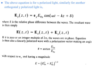
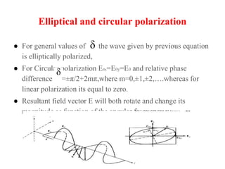
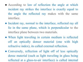
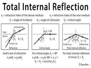
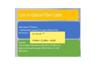
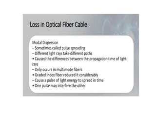
This document discusses the evolution of communication systems and fiber optic technology. It begins by outlining the basic elements of any communication system, including an information source, transmitter, transmission channel, and receiver. It then describes the evolution of early communication systems from fire signals to telegraphs. The development of lasers in 1960 enabled the advent of fiber optic systems by providing a coherent light source. Fiber optic systems have advantages over copper systems like lower loss, wider bandwidth, immunity to interference, and signal security. The key elements of a fiber optic transmission link are described, including the transmitter, fiber cable, receiver, and optional repeaters. Characteristics of light propagation in fibers are also summarized.
The document discusses different types of transmission media including guided media like twisted-pair cable, coaxial cable, and optical fiber as well as unguided or wireless media. It describes the basic characteristics of each type of media such as how they transmit signals, common applications, advantages, and disadvantages. Key topics covered include how different electromagnetic frequencies propagate through different parts of the atmosphere, common standards and specifications for different cable types, and factors that determine the range and bandwidth of each transmission medium.
The document discusses different types of transmission media used for telecommunications including guided media like twisted-pair cable, coaxial cable, and optical fiber as well as unguided or wireless media. It describes the basic characteristics of each type of medium, how they transmit signals, their applications, advantages and disadvantages.
This document provides an overview of optical fiber communication. It discusses how optical fibers can be used to transmit light signals for communication purposes, providing advantages over existing electrical communication systems. Key points include:
- Optical fiber communication uses light signals transmitted through optical fibers. This provides enormous potential bandwidth compared to existing electrical cables.
- Optical fibers are small, lightweight, and electrically isolated, providing advantages for installation and immunity to electromagnetic interference.
- Early optical fibers had high transmission losses, but losses were reduced below 20 dB/km by 1970, allowing commercial deployment of optical communication systems.
The document discusses optical communication and fiber optic communication systems. It defines optical communication as using light to carry information over distances. The most common wavelengths used fall between 0.83-1.55 microns. Optical communication can be analog or digital. Fiber optic communication uses total internal reflection to transmit pulses of light through optical fibers to carry digital data. A fiber optic system includes a transmitter that converts electrical signals to light pulses and a receiver that converts the light pulses back to electrical signals.
The document discusses various topics related to transmission media and the physical layer of the OSI model. It describes guided media like twisted pair cable, coaxial cable, and fiber optic cable. It also discusses unguided transmission using radio waves and microwaves. It explains how signals are transmitted over different media and modulation techniques. It provides details on telephone systems, multiplexing, and how fiber optic networks have replaced older copper networks.
1. The document describes an optical communications course that aims to help students understand optical fiber communications.
2. The key topics covered include the construction and characteristics of optical fibers, optical signal sources and detectors, signal distortion in fibers, and the design of optical systems and wavelength division multiplexing (WDM).
3. The course objectives are for students to understand the significance of optical fiber communications and be able to analyze fiber parameters, design optical systems, and understand signal propagation and detection.
This document provides an overview of optical fiber communication. It discusses the history and development of optical fibers, including the discovery of total internal reflection and development of glass coatings to reduce signal loss. It describes the basic components of an optical communication system including light sources, fiber cables, and light detectors. It also covers fiber types, advantages like high bandwidth and low signal degradation, and disadvantages such as higher initial cost compared to copper cables.
Optical fibers transmit light through thin glass or plastic strands. They work using the principle of total internal reflection. Light traveling through the fiber's core at an angle greater than the critical angle will reflect off the cladding instead of passing through. This allows fibers to carry signals over long distances with minimal loss. Optical fibers have advantages over metal cables like greater bandwidth, lighter weight, immunity to electromagnetic interference, and ability to carry more data. Their main uses are in telecommunications, local area networks, cable TV, and medical endoscopy.
This document provides an overview of optical fiber communication (OFC). It begins with the historical development and need for optical systems due to limitations of traditional communication methods. The basics of OFC are explained, including the system block diagram and principles of operation using ray theory and total internal reflection. Different types of optical fibers are described based on refractive index, materials, and propagation mode. Key aspects like attenuation, bandwidth, and dispersion that influence transmission characteristics are covered. Finally, common optical components used in OFC systems like fiber splices, connectors, and couplers are outlined.
This document provides an overview of optical fiber communication (OFC). It begins with the historical development and need for optical systems due to limitations of traditional communication methods. The basics of OFC are explained, including the system block diagram and principles of operation using ray theory and total internal reflection. Fiber types and transmission characteristics such as attenuation and bandwidth are covered. Finally, key optical components used in OFC systems such as fiber splices, connectors, and couplers are outlined.
The document is an optical communication lab manual that outlines 8 experiments on optical fibers and fiber optic communication. Experiment 1 involves demonstrating different types of optical fibers and connectors. Experiment 2 establishes a 650nm fiber optic analog link. Experiment 3 establishes a 650nm digital fiber optic link. Experiment 4 studies intensity modulation using an analog input signal, transmitting it over fiber, and demodulating the output. Experiment 5 is similar but uses a digital input signal.
This document discusses transmission systems in satellite communications. It begins by defining a transmission line as a device that transmits or guides energy from one point to another. It then discusses how transmission lines carry alternating current and are used to connect radio transmitters and receivers. The document goes on to describe the key components of fiber optic and wireless transmission systems, including transmitters, receivers, optical fiber cables, antennas, and amplifiers. It explains how each component functions and its role in transmitting signals across long distances.
Transmission lines guide electrical energy from one point to another. They have two ends - an input end connected to the source, and an output end connected to the load. Common types of transmission lines include twisted pair, coaxial cable, and optical fiber. Twisted pair comes in unshielded and shielded variants, with shielded providing better protection against interference. Coaxial cable carries signals of higher frequencies than twisted pair. Optical fiber uses light pulses to transmit data over long distances at high speeds. Wireless transmission uses electromagnetic waves like radio waves, microwaves, and infrared to transmit data through the air without a physical medium.
This document provides an overview of optical fiber communications. It discusses the history of fiber optics, including how fiber transmission improved on electrical transmission. The key advantages of optical fibers are described. The electromagnetic spectrum is shown, focusing on the optical spectral bands used for fiber communications. The document outlines the windows and spectral bands designated for fiber optic links. It also discusses network information rates and standards for optical fiber communications.
This document presents an overview of optical communication systems and optical fiber technology. It begins with an introduction to optical communication and the basic components of an optical communication system. It then discusses optical fibers in more detail, including their evolution, structure, and how they work based on the principle of total internal reflection. The document outlines the advantages of optical communication systems, such as wider bandwidth and immunity to interference, as well as some disadvantages like higher cost and difficulty in installation. It concludes by discussing applications of optical fiber technology in various industries.
This document is a physics project file submitted by a student on the topic of optical fibres. It includes an acknowledgements section thanking those who helped with the project. There is a certificate certifying that the student completed the project. The contents section lists topics covered such as principles of operation, applications, and manufacturing of optical fibres. The document provides details on how optical fibres work using total internal reflection to transmit light signals along the fibre. It discusses applications for communication and sensing and factors that cause attenuation in signals.
This document outlines the objectives and outcomes of the course EC8751-Optical Communication. The key objectives are to study optical fiber modes, materials, fabrication, transmission characteristics, optical sources and detectors, receiver systems, and measurements. The outcomes are to understand basic fiber elements, analyze dispersion and polarization techniques, design optical components, construct receiver systems, and design communication systems and networks. It provides textbook references and outlines topics like fiber structure, types, applications, generation of optical fiber communication systems, and fiber materials.
This document summarizes key concepts about optical amplifiers and networks. It discusses how optical amplifiers work by stimulating emission to amplify light, and describes common amplifier types like semiconductor optical amplifiers, doped fiber amplifiers, and Raman amplifiers. It also provides details on erbium-doped fiber amplifiers, including their operation, architecture, and use in telecommunication networks using SONET/SDH protocols. SONET/SDH networks are often configured in ring topologies to provide protection against link and node failures.
The document discusses various topics related to physical layer communication including:
1. Bandwidth-limited signals and the relationship between data rate and harmonics.
2. Different transmission media such as magnetic media, twisted pair, coaxial cable, and fiber optics. It describes their properties and applications.
3. Wireless transmission using different parts of the electromagnetic spectrum such as radio waves, microwaves, and infrared. It also discusses communication satellites.
- This document provides an overview of an introductory lecture on optical communication. It defines key terms like light, photon, and electromagnetic radiation. It explains that light has both particle and wave properties.
- The document outlines the evolution of optical communication technologies from early systems using sunlight or smoke signals to current fiber optic networks. It also discusses how innovations like lasers, optical fibers, amplifiers, and dense wavelength-division multiplexing have increased data rates and transmission distances over time.
- The significance of optical communication systems is that they allow vastly higher bandwidth and lower transmission costs per bit compared to electrical networks.
Optical communications uses optical fibers to transmit large amounts of data over long distances. Optical fibers guide light through the process of total internal reflection. They have several advantages over copper wires like higher bandwidth, less signal loss, immunity to electromagnetic interference, and lower costs. An optical fiber consists of a core and cladding layer. Single-mode fibers carry a single light mode while multi-mode fibers carry multiple light modes. A fiber optic communication system includes a transmitter that converts electrical signals to light, the optical fiber as the transmission medium, and a receiver that converts light back to electrical signals. Common applications of fiber optics include telecommunications networks, cable television, medical devices, and military communications.
The document provides an introduction to fiber optics and discusses several key topics:
1. It describes the basic components and operation of an optical fiber system including the transmitter, fiber cable, and receiver. Light pulses are transmitted through the fiber and detected at the receiving end.
2. The evolution of fiber optic systems is summarized from first to fifth generations with increasing bit rates and transmission distances over time.
3. The basic structure and properties of optical fibers are outlined, including the core, cladding, buffer, and jacket layers. Total internal reflection within the core allows light to propagate along the fiber.
4. Two main fiber types - step index and graded index - are introduced based on differences in their refractive
The document discusses various optical phenomena including reflection, refraction, and total internal reflection. It explains that optical fibers use total internal reflection to guide light along the fiber. Optical fibers have a core with a higher refractive index than the cladding. This allows total internal reflection to contain light within the core. The document also discusses the historical development of optical fiber communications, describing the progression from early generations with lower data rates and shorter distances to current generations with multi-terabit capacities over extremely long ranges. Overall, the document provides an overview of fundamental optical concepts and the evolution of optical fiber communication technology.
This document discusses optical fibers, including their history, structure, working principle, classification, applications, advantages, and disadvantages. Optical fibers guide light and are made of glass or plastic. They were first demonstrated in the 1840s and used for image transmission in the 1920s. An optical fiber has a core and cladding, with the core having a higher refractive index to allow total internal reflection of light. Optical fibers are classified by mode and refractive index profile. They transmit data with high bandwidth and security over long distances at low power. However, initial installation costs are high. Optical fibers now have applications in telecommunications, broadband, medicine, and more.
Analyzing the Different Parameters of Dipole AntennaIJEEE
Ultra wideband is a wireless technology to realize high speed communications which is performed in wideband. In this paper the wideband dipole antenna is designed.
Optical fibers guide light through total internal reflection. They consist of a core with a higher refractive index surrounded by cladding with a lower refractive index. Light entering the core at an angle greater than the critical angle is reflected at the core-cladding interface. This allows light to be transmitted over long distances with little attenuation. Optical fiber communication systems transmit digital data as light pulses using an encoder, transmitter, fiber optic waveguide, receiver and decoder.
This document provides information about the course "Optical Fiber Communication" with course code EEE 409. The 3-page document includes details about the course contents, which cover topics such as guided and unguided optical communication systems, optical fibers, fiber modes, transmission impairments, fiber cabling process and more. It also lists the course teacher, credit hours, textbooks and references.
Introduction- e - waste – definition - sources of e-waste– hazardous substances in e-waste - effects of e-waste on environment and human health- need for e-waste management– e-waste handling rules - waste minimization techniques for managing e-waste – recycling of e-waste - disposal treatment methods of e- waste – mechanism of extraction of precious metal from leaching solution-global Scenario of E-waste – E-waste in India- case studies.
CHINA’S GEO-ECONOMIC OUTREACH IN CENTRAL ASIAN COUNTRIES AND FUTURE PROSPECTjpsjournal1
The rivalry between prominent international actors for dominance over Central Asia's hydrocarbon
reserves and the ancient silk trade route, along with China's diplomatic endeavours in the area, has been
referred to as the "New Great Game." This research centres on the power struggle, considering
geopolitical, geostrategic, and geoeconomic variables. Topics including trade, political hegemony, oil
politics, and conventional and nontraditional security are all explored and explained by the researcher.
Using Mackinder's Heartland, Spykman Rimland, and Hegemonic Stability theories, examines China's role
in Central Asia. This study adheres to the empirical epistemological method and has taken care of
objectivity. This study analyze primary and secondary research documents critically to elaborate role of
china’s geo economic outreach in central Asian countries and its future prospect. China is thriving in trade,
pipeline politics, and winning states, according to this study, thanks to important instruments like the
Shanghai Cooperation Organisation and the Belt and Road Economic Initiative. According to this study,
China is seeing significant success in commerce, pipeline politics, and gaining influence on other
governments. This success may be attributed to the effective utilisation of key tools such as the Shanghai
Cooperation Organisation and the Belt and Road Economic Initiative.
Low power architecture of logic gates using adiabatic techniquesnooriasukmaningtyas
The growing significance of portable systems to limit power consumption in ultra-large-scale-integration chips of very high density, has recently led to rapid and inventive progresses in low-power design. The most effective technique is adiabatic logic circuit design in energy-efficient hardware. This paper presents two adiabatic approaches for the design of low power circuits, modified positive feedback adiabatic logic (modified PFAL) and the other is direct current diode based positive feedback adiabatic logic (DC-DB PFAL). Logic gates are the preliminary components in any digital circuit design. By improving the performance of basic gates, one can improvise the whole system performance. In this paper proposed circuit design of the low power architecture of OR/NOR, AND/NAND, and XOR/XNOR gates are presented using the said approaches and their results are analyzed for powerdissipation, delay, power-delay-product and rise time and compared with the other adiabatic techniques along with the conventional complementary metal oxide semiconductor (CMOS) designs reported in the literature. It has been found that the designs with DC-DB PFAL technique outperform with the percentage improvement of 65% for NOR gate and 7% for NAND gate and 34% for XNOR gate over the modified PFAL techniques at 10 MHz respectively.
We have compiled the most important slides from each speaker's presentation. This year’s compilation, available for free, captures the key insights and contributions shared during the DfMAy 2024 conference.
A review on techniques and modelling methodologies used for checking electrom...nooriasukmaningtyas
The proper function of the integrated circuit (IC) in an inhibiting electromagnetic environment has always been a serious concern throughout the decades of revolution in the world of electronics, from disjunct devices to today’s integrated circuit technology, where billions of transistors are combined on a single chip. The automotive industry and smart vehicles in particular, are confronting design issues such as being prone to electromagnetic interference (EMI). Electronic control devices calculate incorrect outputs because of EMI and sensors give misleading values which can prove fatal in case of automotives. In this paper, the authors have non exhaustively tried to review research work concerned with the investigation of EMI in ICs and prediction of this EMI using various modelling methodologies and measurement setups.
DEEP LEARNING FOR SMART GRID INTRUSION DETECTION: A HYBRID CNN-LSTM-BASED MODELgerogepatton
As digital technology becomes more deeply embedded in power systems, protecting the communication
networks of Smart Grids (SG) has emerged as a critical concern. Distributed Network Protocol 3 (DNP3)
represents a multi-tiered application layer protocol extensively utilized in Supervisory Control and Data
Acquisition (SCADA)-based smart grids to facilitate real-time data gathering and control functionalities.
Robust Intrusion Detection Systems (IDS) are necessary for early threat detection and mitigation because
of the interconnection of these networks, which makes them vulnerable to a variety of cyberattacks. To
solve this issue, this paper develops a hybrid Deep Learning (DL) model specifically designed for intrusion
detection in smart grids. The proposed approach is a combination of the Convolutional Neural Network
(CNN) and the Long-Short-Term Memory algorithms (LSTM). We employed a recent intrusion detection
dataset (DNP3), which focuses on unauthorized commands and Denial of Service (DoS) cyberattacks, to
train and test our model. The results of our experiments show that our CNN-LSTM method is much better
at finding smart grid intrusions than other deep learning algorithms used for classification. In addition,
our proposed approach improves accuracy, precision, recall, and F1 score, achieving a high detection
accuracy rate of 99.50%.
Electric vehicle and photovoltaic advanced roles in enhancing the financial p...IJECEIAES
Climate change's impact on the planet forced the United Nations and governments to promote green energies and electric transportation. The deployments of photovoltaic (PV) and electric vehicle (EV) systems gained stronger momentum due to their numerous advantages over fossil fuel types. The advantages go beyond sustainability to reach financial support and stability. The work in this paper introduces the hybrid system between PV and EV to support industrial and commercial plants. This paper covers the theoretical framework of the proposed hybrid system including the required equation to complete the cost analysis when PV and EV are present. In addition, the proposed design diagram which sets the priorities and requirements of the system is presented. The proposed approach allows setup to advance their power stability, especially during power outages. The presented information supports researchers and plant owners to complete the necessary analysis while promoting the deployment of clean energy. The result of a case study that represents a dairy milk farmer supports the theoretical works and highlights its advanced benefits to existing plants. The short return on investment of the proposed approach supports the paper's novelty approach for the sustainable electrical system. In addition, the proposed system allows for an isolated power setup without the need for a transmission line which enhances the safety of the electrical network
Harnessing WebAssembly for Real-time Stateless Streaming PipelinesChristina Lin
Traditionally, dealing with real-time data pipelines has involved significant overhead, even for straightforward tasks like data transformation or masking. However, in this talk, we’ll venture into the dynamic realm of WebAssembly (WASM) and discover how it can revolutionize the creation of stateless streaming pipelines within a Kafka (Redpanda) broker. These pipelines are adept at managing low-latency, high-data-volume scenarios.
2. Evolution of communication system
● Principal interests of human beings has been to devise communication
systems for sending messages from one distant place to another.The
fundamental elements of any such communication system is shown Fig 1-1
● Information source-inputs message to transmitter
● Transmitter –couples message to transmission channel(Channel- medium
bridging distance between transmitter and receiver.Types:
1)guided:wire/waveguide
● 2)Unguided:atmospheric/space channel.
● Signal while traversing through channel, it may be attenuated and distorted
with distance
● Receiver- Extract weakened and distorted signal from channel,amplify it
and restore to original form
3. FORMS OF COMMUNICATION SYSTEM
Motive:
● to improve fidelity,
● increase data rate so more information could be send
● Increase transmission distance between relay stations.
Evolution:
● Before 19th century-use of fire signal by greeks in 8th century B.C for sending
alarms,calls for help or announcements of certains events.
● 150B.c.-optical signals were encoded relation to alphabet,so any message could be
sent
Limitations: eye used as receiver,LOS transmission paths required.
● Telegraph _Samuel.F.B.Morse in 1838 (1844-commercial telegraph implemented)
● Used wire cables for information transmission-High frequency carriers used –
bandwidth increased so as information capacity.
Applications:Televeision,Radar,Microwavelink
● Transmission media used :millimeter and microwave waveguide,metallic wires
● Another part of EM spectrum is optical range 50nm(ultraviolet)to about
100Micrometer(far infrared),visible spectrum (400nm to 700nm)band.
4. Evolution of Fiber optic system
● Advent of laser (coherent source)in 1960 paved way for this system.
● Optical frequency is 5x10^14Hz, information capacity is 10^5 times greater than
microwave system(~10 million TV channels)
● Unguided limitations: atmospheric channel by rain,fog,snow and dust make high-speed
carrier system economically unattractive in view of present demand of channel capaciy.
● It covers only short-distance(up to 1 km)
● Optical fiber-more reliable and versatile optical channel than atmosphere,but extremely
large loss(morethan 1000dB/km) made them impractical
● Lossses due to impurities in fiber material.In 1970, silica fiber having 20dB/km attenuation
was fabricated.Later attenuation reduced to 0.16dB/km at 1550-num
● Development of optical fiber system grew from combination of semiconductor
technology(gives light sources and photodetectors and optical waveguide technology)
5. Advantages over conventional copper systems
● Low transmission loss and wide bandwidth:
⮚ carry more data over long distance
⮚ Decreased no. of.wires
⮚ Reduced no. of repeaters, this in turn decreases system cost and complexity
● Small size and weight:
⮚ Low weight ,small(hair-sized)
● Advantages in aircraft, satellites and ships
● Immunity to interference:
⮚ Fibers are dielectric in nature ,so they are immune to EMI(Electromagnetic
interference) like inductive pickup from signal-carrying wires and
lightning. And EMP(pulse) effects which is useful in military applications.
● Electrical isolation: Fibers made of glass(insulator)enable them to be
attractive in hazardous environments as it creates no arcing or sparking.
● Signal security: opaque jacketing around fiber make optical signal well
confined in waveguide.can be used in banking,computer networks and
military systems
7. Elements of an optical fiber transmission
link(2/4)
Key sections:
● Transmitter-Consists of light source and its associated drive circuitry
● Cable-offering mechanical and environmental protection to optical fibers
inside
● Receiver-consists of photodetector plus amplification and signal-restoring
circuitry.
● Additional components: optical connectors,splices,couplers or beam
splitters and repeaters
⮚Optical fiber is one of the most important elements in optical fiber link
⮚Installation can be done either aerial,in ducts,undersea, or buried
directly in the ground.
● Length: several hundred meters to several km for long-distance pplications
8.
9. Elements of an optical fiber transmission
link(3/4)
● Light source : LED / laser-light output modulated rapidly
by simply varying bias current.
● Electrical input to transmitter can be analog/digital
● Optical source is a square –law device, that a linear
variation in drive current results in linear change in
optical output power
⮚For 800-900 nm light source alloys are GaAIAs.
⮚For 1100 -1600 nm,InGaAsP
● Photodiode: progressively attenuated and distorted signal
because of scattering,absorption, and dispersion
mechanisms in the wavegudie will be detectec.
10. Elements of an optical fiber transmission
link(3/4)
● Analagous to light soruce, detectors is also a square-law device (convert
received optical power to electric current output).
⮚Types:pin and avalanche photodiodes(APDs){for low power signal}.Both
has exhibit high efficiency and response speed.
● Receiver: more complex than transmitter, since it has to both amplify and
reshape the degraded signal received by photodetector.
● Figure of merit for a receiver is the minimum optical power necessary at
the desired data rate to attain either a given error probability for digital
systems or a specifiied SNR for a n analog system.
● Repeater –need in transmission line to amplify and reshape the signal.(it
consists of receiver and transmitter placed back to back)
● Receiver :detect optical signal and converts to electric signal, which is
amplified, reshaped, and sent to electric input of transmitter section.
● Transmitter section convert electric signal to optical signal and sends it on
11. optical fiber
● An optical fiber (or fibre) is a flexible, transparent fiber made
by drawing glass (silica) or plastic to a diameter slightly thicker than
that of a human hair.
● Optical fibers are used most often as a means to transmit
light between the two ends of the fiber and find wide usage in fiber-
optic communications, where they permit transmission over longer
distances and at higher bandwidths (data transfer rates) than
electrical cables.
● Fibers are used instead of metal wires because signals travel along
them with less loss; in addition, fibers are immune
to electromagnetic interference, a problem from which metal wires
suffer.
● Fibers are also used for illumination and imaging, and are often
wrapped in bundles so they may be used to carry light into, or
images out of confined spaces, as in the case of a fiberscope.
13. Optical fiber structure
● Optical fibers typically include a core surrounded by a
transparent cladding material with a lower index of refraction.
● Light is kept in the core by the phenomenon of total internal
reflection which causes the fiber to act as a waveguide.
● Fibers that support many propagation paths or transverse
modes are called multi-mode fibers, while those that support a
single mode are called single-mode fibers (SMF).
● Multi-mode fibers generally have a wider core diameter and
are used for short-distance communication links and for
applications where high power must be transmitted.
15. Characterisitcs and Behaviour of light
● Fiber optics technology involves the emission, transmission,
and detection of light let us discuss the nature of light.
● Two methods usually used to describe how optical fiber guides
light.
● Geometrical or ray optics concepts of light: reflection and
refraction to provide an intuittive picture of the propagation
mechanisms.
● Electromagnetic wave approach: where light is treated as an
EM wave which propagates along the optical fiber
waveguide.(This involves maxwell’s equation subject to
cylindrical boundary conditions of fiber.)
16. The nature of light
● Until 17th century, it is believed that light consists of a stream of minute particles
that are emitted by luminous sources.
● Particles travel in straight line , and assumed to penetrate transparent but reflected
from opaque ones.
● Described large-scale optical effects like reflection and refraction, but failed to
explain interference and diffraction.
● Diffraction explanation given by Fresnel in 1815 could be interpreted on
assumption that light is a wave motion.
● In 1864, Maxwell theorized that light waves must be electromagnetic in nature.
● After observation of polarization effects indicated that light waves are
transverse(that is, the wave motion is perpendicular to the direction in which the
wave travels).
● In wave or physical optical view point EM waves radiated by small optical source
can be represented by train of spherical wave front(locus of all points in the wave
train which have the same phase).
● If wavelength of light is smaller than object(or opening ) which it encounters, the
wavefront appears as straight lines to this object or opening. In this case, light wave
can be represented as a plane wave, and its direction of travel can be indicated by
21. Addition of two linearly polarized waves
having zero relative phase between them.
22. Elliptical and circular polarization
● For general values of the wave given by previous equation
is elliptically polarized,
● For Circular polarization E0x=E0y=E0 and relative phase
difference =±π/2+2mπ,where m=0,±1,±2,….whereas for
linear polarization its equal to zero.
● Resultant field vector E will both rotate and change its
magnitude as function of the angular frequency w.
23. Quantum nature of light
● In dealing with interaction of light and matter, such as occurs
in dispersion and in the emission and absorption of light,
neither the particle theory nor the wave theory of light is
appropriate.
● Quantum theory – consider particle as well as wave
properties.(particle nature arises from observation that light
energy is always emitted or absorbed in discrete units called
quanta or photons.)
● Photon energy depend only on frequency ,which in turn must
be measure by observing wave property of light.
● Relation between energy E and frequency V of a photon is
24. Basic optical laws and definitions
● Fundamental optical parameter of material is refractive index
(or index of refraction).
● In free space, light travels at a speed of c=3*10^8m/s.
● Speed of light related to frequency v wavelength λ by c=v λ
● Upon entering a dielectric or nonconducting medium the wave
now travels at a speed v,which is characteristics of material
and less than c.
● The ratio of the speed of light in a vacuum to that in matter is
the index of refraction n of the material and is given by,
● n=c/v
● Values of n are (1.00 for air, 1.33 for water, 1.50 for glass ,a
27. ● According to law of reflection the angle at which
incident ray strikes the interface is exactly equal to
the angle the reflected ray makes with the same
interface.
● Incident ray, normal to the interface, reflected ray all
lie in the same plane, which is perpendicular to the
interface plane between two materials.
● When light traveling in certain medium is reflected
off an optically denser material (one with high
refractive index), its called external reflection.
● Conversely, reflection of light off of less optically
dense material (such as light traveling in glass being
reflected at a glass-to-air interface) is called internal
28. Condition required for total internal reflection can be determined by using
snell’s law.
32. Total Internal Reflection Problems
● Problem (1): An unknown glass has an index of refraction of n=1.5 . For a
beam of light originated in the glass, at what angles the
light 100% reflected back into the glass. (The index of refraction of air
is nair=1.00).
34. Total Internal Reflection Problems
Consider the optical fiber from Fig . The index of refraction of the inner
core is 1.480 , and the index of refraction of the outer cladding is 1.44.
A.What is the critical angle for the core-cladding interface?
B.For what range of angles in the core at the entrance of the fiber (q2) will the
light be completely internally reflected at the core-cladding interface?
C.What range of incidence angles in air does this correspond to?
D.If light is totally internally reflected at the upper edge of the fiber, will it
necessarily be totally internally reflected at the lower edge of the fiber
(assuming edges are parallel)?
39. Acceptance Angle
● Acceptance angle is the maximum angle with the axis of the Optical Fiber at
which the light can enter into the optical fiber in order to be propagated
through it
40. Acceptance Angle Derivation
● Let us consider an optical fibre having a core with refractive index n1 and
cladding with refractive index n2 such that (n1> n2).
● The refractive index of the launching medium is n0.
● Let us consider a light ray AO enters the fiber making an angle Theta i with its
axis.
● OB is the refracted ray that makes an angle Theta r with the axis and strikes
core-cladding interface at an angle, which is greater than critical angle.
● Thus, it undergoes total internal reflection at the interface
41.
42.
43.
44. Numerical Aperture
● Numerical aperture in case of optical fiber communication can be defined as-
"The light gathering (collecting) capacity of an optical fibre".
● The numerical aperture provides important relationship between acceptance
angle and the refractive index of the core and cladding
45.
46. Problem 1:
The Refractive Indices of core and cladding are 1.50 and 1.48 respectively in an Optical Fiber.Find the Numerical
Aperture and Acceptance Angle
47. 2.An Optical Fiber has a core material with refractive index 1.55 and its cladding material has a refractive
index of 1.50.The Light is launched into it in air.Calculate its numerical aperture,the acceptance angle and
also fractional index change
48.
49. Ray Optics
● Optics is the study of light and its interaction with matter.
● Light is visible electromagnetic radiation, which transports energy and momentum
(linear and angular) from source to detector.
● Photonics includes the generation, transmission,
modulation,amplification,frequency conversion and detection of light.
● Ray optics is the simplest theory of light. Rays travel in optical media according
to a set of geometrical rules; hence ray optics is also called geometrical optics.
● Ray optics is an approximate theory, but describes accurately a variety of
phenomena.
● Ray optics is concerned with the locations and directions of light rays, which carry
photons and light energy (They also carry momentum, but the direction of the
momentum may be different from the ray direction).
● It is useful in describing image formation, the guiding of light, and energy
transport.
50. Postulates of Ray Optics
1. Light travels in the form of rays (can think of rays as photon currents).Rays are
emitted by light sources, and can be observed by light detectors.
2. An optical medium (through which rays propagate) is characterized by a real
scalar quantity n ≥ 1, called the refractive index. The speed of light in vacuum is c
= 3 × 10⁸m/s.The speed of light in a medium is v = c/n; this is the definition of the
refractive index. The time taken by light to cover a distance d is t = nd/c; it is
proportional to nd, which is called the optical path length.
51. Postulates of Ray Optics
3. In an inhomogeneous medium, the refractive index n(r) varies with
position; hence the optical path length OPL between two points A and B is
where ds is an element of length along the path. The time t taken by light to
go from A to B is t = OPL/c.
52. Types of Rays
Rays that Interact with surfaces
● An incident ray is a ray of light that strikes a surface. The angle between this
ray and the perpendicular or normal to the surface is the angle of incidence
● The reflected ray corresponding to a given incident ray, is the ray that
represents the light reflected by the surface. The angle between the surface
normal and the reflected ray is known as the angle of reflection. The Law of
Reflection says that for a specular (non-scattering) surface, the angle of
reflection is always equal to the angle of incidence.
53. Postulates of Ray Optics
4.Light rays between the points A and B follow a path such that the time of travel,
relative to neighboring paths, is an extremum (minimum). This means that the
variation in the travel time, or, equivalently,in the optical path lenght, is zero. That
is,
Usually, the extremum is a minimum; then light rays travel along the path of least
time. If there are many paths with the minimum time, then light rays travel along all
of these simultaneously.
54. Types of rays
● The refracted ray or transmitted ray corresponding to a given incident ray
represents the light that is transmitted through the surface. The angle
between this ray and the normal is known as the angle of refraction, and it is
given by Snell's Law. Conservation of energy requires that the power in the
incident ray must equal the sum of the power in the refracted ray, the power
in the reflected ray, and any power absorbed at the surface
● If the material is birefringent, the refracted ray may split into ordinary and
extraordinary rays, which experience different indexes of refraction when
passing through the birefringent material.
55. Types of rays
● The principal ray or chief ray (sometimes known as the b ray) in an optical
system is the meridional ray that starts at the edge of the object, and passes
through the center of the aperture stop
● Sagittal ray or transverse ray
● Paraxial ray
● Parabasal ray
56. Types of rays
Optical systems
● A meridional ray or tangential ray is a ray that is
confined to the plane containing the system's
optical axis and the object point from which the
ray originated.
● A skew ray is a ray that does not propagate in a
plane that contains both the object point and the
optical axis. Such rays do not cross the optical
axis anywhere, and are not parallel to it.
● The marginal ray (sometimes known as an a ray
or a marginal axial ray) in an optical system is the
meridional ray that starts at the point where the
object crosses the optical axis, and touches the
edge of the aperture stop of the system.
57. UNIT I - S7,S8,S9- Topics
Optical fiber modes, Optical fiber
configurations, Single mode
fibers, Multimode Fibers, Step
Index Fibers, Graded IndEX
FIBERS
58. Optical fiber modes
● Optical fiber is classified into 2 categories
1. Number of modes
○ Single Mode Fiber (SMF)
○ Multi Mode Fiber (MMF)
2. Refractive Index
○ Step Index (Single mode/ Munltimode)
○ Graded Index
60. Single mode fiber
● Only one mode can propagate through the fiber
● Core diameter (5um) and high cladding diameter (70um)
● Difference between the R.I of core and cladding is very small.
● There is neither dispersion nor degradation therefore it is suitable for long
distance communication.
● Light is passed through the single mode fiber through laser diode.
61. Multimode fiber
● Allows large number of modes for light ray travelling through it.
● Core diameter is 40un and Cladding is 70um
● The relative refractive index is larger than single mode fiber.
● Due to multimode dispersion, signal degradation takes place.
● Not suitable for long distance communication due to large dispersion and
attenuation.
64. Single mode step index fiber
● A single mode or monomode step index fiber allows the propagation of
only one traverse electromagnetic mode and hence the core diameter
must be of the order of 2 µm to 10µm. It has high information carrying
capacity.
65.
66. Multi mode Step Index fiber
● The Refractive index for core and cladding are constant.
● The light ray propagate through it in the form of meridiognal rays which
cross the fiber axis during every reflection at the core cladding boundary.
69. Multimode Graded Index fiber
Fiber core has a non-uniform refractive index that gradually
decreases from the center towards the core cladding
interface.
● Cladding has uniform Refractive index,
● Light rays propagate through it in the form of helical rays.