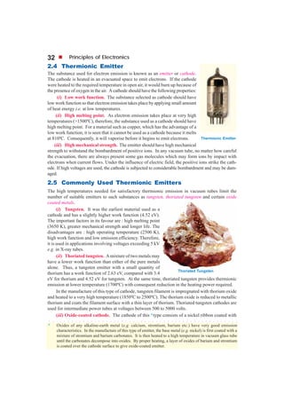
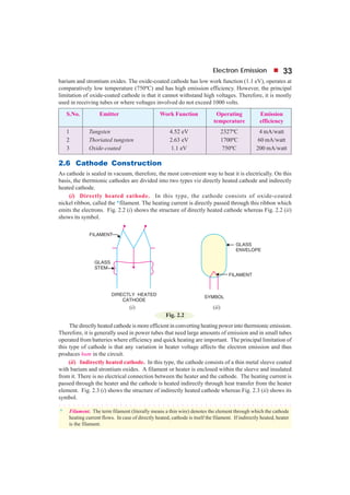
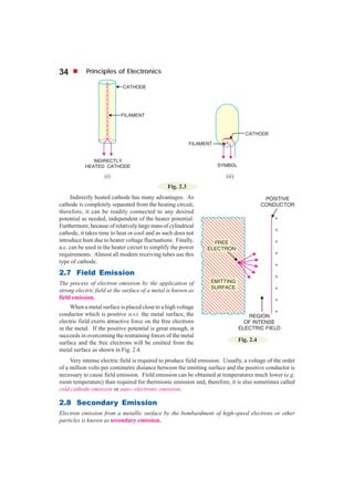
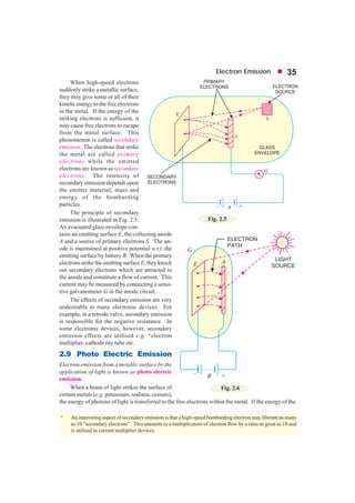
This document discusses different types of electron emission from metal surfaces. There are four principal types: thermionic emission, where heating provides the energy for electrons to overcome the work function; field emission, where a strong electric field pulls electrons from the surface; photoelectric emission, where light energy is transferred to electrons; and secondary emission, where high-velocity electrons striking the surface knock out more electrons. Thermionic emission is described in more detail, including the Richardson-Dushman equation that relates emission current density to temperature and work function, and examples are provided to calculate emission currents and determine metal work functions.
This Presentation "Energy band theory of solids" will help you to Clarify your doubts and Enrich your Knowledge. Kindly use this presentation as a Reference and utilize this presentation
Energy bands consisting of a large number of closely spaced energy levels exist in crystalline materials. The bands can be thought of as the collection of the individual energy levels of electrons surrounding each atom. The wavefunctions of the individual electrons, however, overlap with those of electrons confined to neighboring atoms. The Pauli exclusion principle does not allow the electron energy levels to be the same so that one obtains a set of closely spaced energy levels, forming an energy band. The energy band model is crucial to any detailed treatment of semiconductor devices. It provides the framework needed to understand the concept of an energy bandgap and that of conduction in an almost filled band as described by the empty states.
Fundamentals of learn how to Semiconductors can easily be mani pulated to become conducting or insulating materials and can change their conductive properties
IIT JEE PHYSICS CLASS NOTES UPLOADED BY Er. AMBARISH SRIVASTAVA (AIR 538)Ambarish Srivastava
IIT JEE PHYSICS NOTES PART 6
Semiconductor Devices, Principles of Communication,
Diffraction, Polarization.
Uploaded by Ambarish Srivastava
Thanks to my student Harsh Pruthi (2014 batch) for Making Nice Notes
I gave this presentation in my university as part of the High Voltage Engineering course. The contents of this presentation are as follows:
1) Ionization Process
2) Gases as Insulating Medium
3) Secondary Ionization
4) Cathode Process
5) Types of Cathode Processes
Study Some Parameters of Electrical Discharge in N2 and CO2 Without and With ...IOSRJECE
:We study the breakdown voltage under low pressure for N2, CO2 gases of with a magnetic field to the electrode of iron and aluminum with diameter (8.8cm) cm and distance separation between them is (3cm). by using Passion curve, we measur less effort collapsed, and we notice that less effort is linked to the collapse of a function held cities and when the magnetic field will be reduced to shed breakdown voltage. Since the breakdown voltage for CO2 is greater than breakdown voltage N2. Through curved Passion was calculated (훾) and when to shed the magnetic field will increase in value
Securing your Kubernetes cluster_ a step-by-step guide to success !KatiaHIMEUR1
Today, after several years of existence, an extremely active community and an ultra-dynamic ecosystem, Kubernetes has established itself as the de facto standard in container orchestration. Thanks to a wide range of managed services, it has never been so easy to set up a ready-to-use Kubernetes cluster.
However, this ease of use means that the subject of security in Kubernetes is often left for later, or even neglected. This exposes companies to significant risks.
In this talk, I'll show you step-by-step how to secure your Kubernetes cluster for greater peace of mind and reliability.
Builder.ai Founder Sachin Dev Duggal's Strategic Approach to Create an Innova...Ramesh Iyer
In today's fast-changing business world, Companies that adapt and embrace new ideas often need help to keep up with the competition. However, fostering a culture of innovation takes much work. It takes vision, leadership and willingness to take risks in the right proportion. Sachin Dev Duggal, co-founder of Builder.ai, has perfected the art of this balance, creating a company culture where creativity and growth are nurtured at each stage.
Neuro-symbolic is not enough, we need neuro-*semantic*Frank van Harmelen
Neuro-symbolic (NeSy) AI is on the rise. However, simply machine learning on just any symbolic structure is not sufficient to really harvest the gains of NeSy. These will only be gained when the symbolic structures have an actual semantics. I give an operational definition of semantics as “predictable inference”.
All of this illustrated with link prediction over knowledge graphs, but the argument is general.
Accelerate your Kubernetes clusters with Varnish CachingThijs Feryn
A presentation about the usage and availability of Varnish on Kubernetes. This talk explores the capabilities of Varnish caching and shows how to use the Varnish Helm chart to deploy it to Kubernetes.
This presentation was delivered at K8SUG Singapore. See https://feryn.eu/presentations/accelerate-your-kubernetes-clusters-with-varnish-caching-k8sug-singapore-28-2024 for more details.
Generating a custom Ruby SDK for your web service or Rails API using Smithyg2nightmarescribd
Have you ever wanted a Ruby client API to communicate with your web service? Smithy is a protocol-agnostic language for defining services and SDKs. Smithy Ruby is an implementation of Smithy that generates a Ruby SDK using a Smithy model. In this talk, we will explore Smithy and Smithy Ruby to learn how to generate custom feature-rich SDKs that can communicate with any web service, such as a Rails JSON API.
Essentials of Automations: Optimizing FME Workflows with ParametersSafe Software
Are you looking to streamline your workflows and boost your projects’ efficiency? Do you find yourself searching for ways to add flexibility and control over your FME workflows? If so, you’re in the right place.
Join us for an insightful dive into the world of FME parameters, a critical element in optimizing workflow efficiency. This webinar marks the beginning of our three-part “Essentials of Automation” series. This first webinar is designed to equip you with the knowledge and skills to utilize parameters effectively: enhancing the flexibility, maintainability, and user control of your FME projects.
Here’s what you’ll gain:
- Essentials of FME Parameters: Understand the pivotal role of parameters, including Reader/Writer, Transformer, User, and FME Flow categories. Discover how they are the key to unlocking automation and optimization within your workflows.
- Practical Applications in FME Form: Delve into key user parameter types including choice, connections, and file URLs. Allow users to control how a workflow runs, making your workflows more reusable. Learn to import values and deliver the best user experience for your workflows while enhancing accuracy.
- Optimization Strategies in FME Flow: Explore the creation and strategic deployment of parameters in FME Flow, including the use of deployment and geometry parameters, to maximize workflow efficiency.
- Pro Tips for Success: Gain insights on parameterizing connections and leveraging new features like Conditional Visibility for clarity and simplicity.
We’ll wrap up with a glimpse into future webinars, followed by a Q&A session to address your specific questions surrounding this topic.
Don’t miss this opportunity to elevate your FME expertise and drive your projects to new heights of efficiency.
The Art of the Pitch: WordPress Relationships and SalesLaura Byrne
Clients don’t know what they don’t know. What web solutions are right for them? How does WordPress come into the picture? How do you make sure you understand scope and timeline? What do you do if sometime changes?
All these questions and more will be explored as we talk about matching clients’ needs with what your agency offers without pulling teeth or pulling your hair out. Practical tips, and strategies for successful relationship building that leads to closing the deal.
Elevating Tactical DDD Patterns Through Object CalisthenicsDorra BARTAGUIZ
After immersing yourself in the blue book and its red counterpart, attending DDD-focused conferences, and applying tactical patterns, you're left with a crucial question: How do I ensure my design is effective? Tactical patterns within Domain-Driven Design (DDD) serve as guiding principles for creating clear and manageable domain models. However, achieving success with these patterns requires additional guidance. Interestingly, we've observed that a set of constraints initially designed for training purposes remarkably aligns with effective pattern implementation, offering a more ‘mechanical’ approach. Let's explore together how Object Calisthenics can elevate the design of your tactical DDD patterns, offering concrete help for those venturing into DDD for the first time!
State of ICS and IoT Cyber Threat Landscape Report 2024 previewPrayukth K V
The IoT and OT threat landscape report has been prepared by the Threat Research Team at Sectrio using data from Sectrio, cyber threat intelligence farming facilities spread across over 85 cities around the world. In addition, Sectrio also runs AI-based advanced threat and payload engagement facilities that serve as sinks to attract and engage sophisticated threat actors, and newer malware including new variants and latent threats that are at an earlier stage of development.
The latest edition of the OT/ICS and IoT security Threat Landscape Report 2024 also covers:
State of global ICS asset and network exposure
Sectoral targets and attacks as well as the cost of ransom
Global APT activity, AI usage, actor and tactic profiles, and implications
Rise in volumes of AI-powered cyberattacks
Major cyber events in 2024
Malware and malicious payload trends
Cyberattack types and targets
Vulnerability exploit attempts on CVEs
Attacks on counties – USA
Expansion of bot farms – how, where, and why
In-depth analysis of the cyber threat landscape across North America, South America, Europe, APAC, and the Middle East
Why are attacks on smart factories rising?
Cyber risk predictions
Axis of attacks – Europe
Systemic attacks in the Middle East
Download the full report from here:
https://sectrio.com/resources/ot-threat-landscape-reports/sectrio-releases-ot-ics-and-iot-security-threat-landscape-report-2024/
Software Delivery At the Speed of AI: Inflectra Invests In AI-Powered QualityInflectra
In this insightful webinar, Inflectra explores how artificial intelligence (AI) is transforming software development and testing. Discover how AI-powered tools are revolutionizing every stage of the software development lifecycle (SDLC), from design and prototyping to testing, deployment, and monitoring.
Learn about:
• The Future of Testing: How AI is shifting testing towards verification, analysis, and higher-level skills, while reducing repetitive tasks.
• Test Automation: How AI-powered test case generation, optimization, and self-healing tests are making testing more efficient and effective.
• Visual Testing: Explore the emerging capabilities of AI in visual testing and how it's set to revolutionize UI verification.
• Inflectra's AI Solutions: See demonstrations of Inflectra's cutting-edge AI tools like the ChatGPT plugin and Azure Open AI platform, designed to streamline your testing process.
Whether you're a developer, tester, or QA professional, this webinar will give you valuable insights into how AI is shaping the future of software delivery.
Epistemic Interaction - tuning interfaces to provide information for AI supportAlan Dix
Paper presented at SYNERGY workshop at AVI 2024, Genoa, Italy. 3rd June 2024
https://alandix.com/academic/papers/synergy2024-epistemic/
As machine learning integrates deeper into human-computer interactions, the concept of epistemic interaction emerges, aiming to refine these interactions to enhance system adaptability. This approach encourages minor, intentional adjustments in user behaviour to enrich the data available for system learning. This paper introduces epistemic interaction within the context of human-system communication, illustrating how deliberate interaction design can improve system understanding and adaptation. Through concrete examples, we demonstrate the potential of epistemic interaction to significantly advance human-computer interaction by leveraging intuitive human communication strategies to inform system design and functionality, offering a novel pathway for enriching user-system engagements.
1. 28 Principles of Electronics
2.1 Electron Emission
2.2 Types of Electron Emission
2.3 Thermionic Emission
2.4 Thermionic Emitter
2.5 Commonly Used Thermionic Emitters
2.6 Cathode Construction
2.7 Field Emission
2.8 Secondary Emission
2.9 Photo Electric Emission
Electron Emission
2
INTRINTRINTRINTRINTRODUCTIONODUCTIONODUCTIONODUCTIONODUCTION
T
he reader is familiar with the current conduction (i.e. flow of electrons) through a conduc-
tor. The valence electrons of the conductor atoms are loosely bound to the atomic nuclei. At
room temperature, the thermal energy in the conductor is adequate to break the bonds of the
valence electrons and leave them unattached to any one nucleus. These unbound electrons move at
random within the conductor and are known as
free electrons. If an electric field is applied across
the conductor, these free electrons move through
the conductor in an orderly manner, thus consti-
tuting electric current. This is how these free elec-
trons move through the conductor or electric cur-
rent flows through a wire.
Many electronic devices depend for their op-
eration on the movement of electrons in an evacu-
ated space. For this purpose, the free electrons
must be ejected from the surface of metallic con- Electron Emission
2. Electron Emission 29
ductor by supplying sufficient energy from some external source. This is known as electron emission.
The emitted electrons can be made to move in vacuum under the influence of an electric field, thus
constituting electric current in vacuum. In this chapter, we shall confine our attention to the various
aspects of electron emission.
2.1 Electron Emission
The liberation of electrons from the surface of a substance is known as electron emission.
For electron emission, metals are used because they
have many free electrons. If a piece of metal is
investigated at room temperature, the random motion
of free electrons is as shown in Fig. 2.1. However, these
electrons are free only to the extent that they may transfer
from one atom to another within the metal but they
cannot leave the metal surface to provide electron
emission. It is because the free electrons that start at
the surface of metal find behind them positive nuclei
pulling them back and none pulling forward. Thus at
the surface of a metal, a free electron encounters forces
that prevent it to leave the metal. In other words, the
metallic surface offers a barrier to free electrons and is
known as surface barrier.
However, if sufficient external energy is given to the free electron, its kinetic energy is increased
and thus electron will cross over the surface barrier to leave the metal. This additional energy required
by an electron to overcome the surface barrier of the metal is called work function of the metal.
The amount of additional energy required to emit an electron from a metallic surface is known
as work function of that metal.
Thus, if the total energy required to liberate an electron from a metal is 4 eV* and the energy
already possessed by the electron is 0.5 eV, then additional energy required (i.e., work function) is
4.0− 0.5 = 3.5 eV. The work function of pure metals varies roughly from 2 to 6 eV. It depends upon
the nature of metal, its purity and the conditions of its surface. It may be noted that it is desirable that
metal used for electron emission should have low work function so that a small amount of energy is
required to cause emission of electrons.
2.2 Types of Electron Emission
The electron emission from the surface of a metal is possible only if sufficient additional energy
(equal to the work function of the metal) is supplied from some external source. This external energy
may come from a variety of sources such as heat energy, energy stored in electric field, light energy or
kinetic energy of the electric charges bombarding the metal surface. Accordingly, there are following
four principal methods of obtaining electron emission from the surface of a metal :
* Work function is the additional energy required for the liberation of electrons. Therefore, it should have
the conventional unit of energy i.e. joules. But this unit is very large for computing electronics work.
Therefore, in practice, a smaller unit called electron volt (abbreviated as eV) is used.
One electron-volt is the amount of energy acquired by an electron when it is accelerated through a poten-
tial difference of 1 V.
Thus, if an electron moves from a point of 0 potential to a point of +10V, then amount of energy acquired
by the electron is 10 eV.
Since charge on an electron = 1.602 × 10
−19
C and voltage = 1 V,
∴ 1 electron-volt = Q V = (1.602 × 10
−19
) × 1 J
or 1 eV = 1.602 × 10
−19
J
Fig. 2.1
○ ○ ○ ○ ○ ○ ○ ○ ○ ○ ○ ○ ○ ○ ○ ○ ○ ○ ○ ○ ○ ○ ○ ○ ○ ○ ○ ○ ○ ○ ○ ○ ○ ○ ○ ○ ○ ○ ○ ○ ○ ○ ○ ○ ○ ○ ○ ○ ○ ○
3. 30 Principles of Electronics
(i) Thermionic emission. In this method, the metal is heated to sufficient temperature (about
2500ºC) to enable the free electrons to leave the metal surface. The number of electrons emitted
depends upon the temperature. The higher the temperature, the greater is the emission of electrons.
This type of emission is employed in vacuum tubes.
(ii) Field emission. In this method, a strong electric field (i.e. a high positive voltage) is
applied at the metal surface which pulls the free electrons out of metal because of the attraction of
positive field. The stronger the electric field, the greater is the electron emission.
(iii) Photo-electric emission. In this method, the energy of light falling upon the metal surface
is transferred to the free electrons within the metal to enable them to leave the surface. The greater the
intensity (i.e. brightness) of light beam falling on the metal surface, the greater is the photo-electric
emission.
(iv) Secondary emission. In this method, a high velocity beam of electrons strikes the metal
surface and causes the free electrons of the metal to be knocked out from the surface.
2.3 Thermionic Emission
The process of electron emission from a metal surface by supplying thermal energy to it is known as
thermionic emission.
At ordinary temperatures, the energy possessed by free electrons in the metal is inadequate to
cause them to escape from the surface. When heat is applied to the metal, some of heat energy is
converted into kinetic energy, causing accelerated motion of free electrons. When the temperature
rises sufficiently, these electrons acquire additional energy equal to the work function of the metal.
Consequently, they overcome the restraining surface barrier and leave the metal surface.
Metals with lower work function will require less additional energy and, therefore, will emit
electrons at lower temperatures. The commonly used materials for electron emission are tungsten,
thoriated tungsten and metallic oxides of barium and strontium. It may be added here that high
temperatures are necessary to cause thermionic emission. For example, pure tungsten must be heated
to about 2300ºC to get electron emission. However, oxide coated emitters need only 750ºC to cause
thermionic emission.
Richardson-Dushman equation. The amount of thermionic emission increases rapidly as the
emitter temperature is raised. The emission current density is given by Richardson-Dushman equa-
tion given below :
Js = A T
2 b
Te
−
amp/m
2
...(i)
where Js = emission current density i.e. current per square metre of the
emitting surface
T = absolute temperature of emitter in K
A = constant, depending upon the type of emitter and is measured
in amp/m2
/K2
b = a constant for the emitter
e = natural logarithmic base
The value of b is constant for a metal and is given by :
b =
e
k
φ
where φ = work function of emitter
e = electron charge = 1.602 × 10⁻¹⁹
coulomb
k = Boltzmann’s constant = 1.38 × 10
−23
J/K
∴ b =
19
23
1.602 10
1.38 10
−
−
φ× ×
×
= 11600 φ K
4. Electron Emission 31
Putting the value of b in exp. (i), we get,
Js =
11600
2 TAT e
φ
−
...(ii)
The following points may be noted from eqn. (ii) :
(i) The emission is markedly affected by temperature changes. Doubling the temperature of an
emitter may increase electron emission by more than 10
7
times. For instance, emission from pure
tungsten metal is about 10− 6
ampere per sq. cm. at 1300ºC but rises to enormous value of about 100
amperes when temperature is raised to 2900ºC.
(ii) Small changes in the work function of the emitter can produce enormous effects on emis-
sion. Halving the work function has exactly the same effect as doubling the temperature.
Example 2.1. A tungsten filament consists of a cylindrical cathode 5 cm long and 0.01 cm in
diameter. If the operating temperature is 2500 K, find the emission current. Given that
A = 60.2 × 10⁴
A/m2
/ K2
, φ = 4.517 eV.
Solution. A = 60.2 × 10
4
amp/m
2
/K
2
, T = 2500 K, φ = 4.517 eV
∴ b = 11600 φ K = 11600 × 4.517 K = 52400 K
Using Richardson-Dushman equation, emission current density is given by :
Js = 2
b
TAT e
−
amp/m
2
= 60.2 × 10
4
× (2500)
2
×
52400
2500
(2.718)
−
= 0.3 × 10
4
amp/m
2
Surface area of cathode, a = π d l = 3.146 × 0.01 × 5 = 0.157 cm2
= 0.157 × 10⁻⁴
m2
∴ Emission current = Js × a = (0.3 × 10
4
) × (0.157 × 10
−4
) = 0.047 A
Example 2.2. A tungsten wire of unknown composition emits 0.1 amp/cm
2
at a temperature of
1900 K. Find the work function of tungsten filament. Determine whether the tungsten is pure or
contaminated with substance of lower work function. Given that A = 60.2 amp/cm2
/K2
.
Solution. Js = 0.1 amp/cm
2
; A = 60.2 amp/cm
2
/K
2
; T = 1900 K
Let φ electron-volt be the work function of the filament.
∴ b = 11600 φ K
Using Richardson-Dushman equation, emission current density is given by :
Js = 2
b
TA T e
−
amp/cm2
or 0.1 = 60.2 × (1900)
2
×
11600
1900
e
φ
−
or
11600
1900
e
φ
− = 2
0.1
60.2 (1900)× = 4.6 × 10⁻¹⁰
or e
−6.1 φ
= 4.6 × 10
−10
or − 6.1 φ loge e = loge 4.6 − 10 loge 10
or − 6.1 φ = 1.526 − 23.02
∴ φ =
1.526 23.02
6.1
−
− = 3.56 eV
Since the work function of pure tungsten is 4.52 eV, the sample must be contaminated. Thoriated
tungsten has a work function ranging from 2.63 eV to 4.52 eV, depending upon the percentage of
metallic thorium. Therefore, the sample is most likely to be thoriated tungsten.
5. 32 Principles of Electronics
Thermionic Emitter
2.4 Thermionic Emitter
The substance used for electron emission is known as an emitter or cathode.
The cathode is heated in an evacuated space to emit electrons. If the cathode
were heated to the required temperature in open air, it would burn up because of
the presence of oxygen in the air. A cathode should have the following properties:
(i) Low work function. The substance selected as cathode should have
low work function so that electron emission takes place by applying small amount
of heat energy i.e. at low temperatures.
(ii) High melting point. As electron emission takes place at very high
temperatures (>1500ºC), therefore, the substance used as a cathode should have
high melting point. For a material such as copper, which has the advantage of a
low work function, it is seen that it cannot be used as a cathode because it melts
at 810ºC. Consequently, it will vaporise before it begins to emit electrons.
(iii) High mechanical strength. The emitter should have high mechanical
strength to withstand the bombardment of positive ions. In any vacuum tube, no matter how careful
the evacuation, there are always present some gas molecules which may form ions by impact with
electrons when current flows. Under the influence of electric field, the positive ions strike the cath-
ode. If high voltages are used, the cathode is subjected to considerable bombardment and may be dam-
aged.
2.5 Commonly Used Thermionic Emitters
The high temperatures needed for satisfactory thermionic emission in vacuum tubes limit the
number of suitable emitters to such substances as tungsten, thoriated tungsten and certain oxide
coated metals.
(i) Tungsten. It was the earliest material used as a
cathode and has a slightly higher work function (4.52 eV).
The important factors in its favour are : high melting point
(3650 K), greater mechanical strength and longer life. The
disadvantages are : high operating temperature (2500 K),
high work function and low emission efficiency. Therefore,
it is used in applications involving voltages exceeding 5 kV
e.g. in X-ray tubes.
(ii) Thoriated tungsten. A mixture of two metals may
have a lower work function than either of the pure metals
alone. Thus, a tungsten emitter with a small quantity of
thorium has a work function of 2.63 eV, compared with 3.4
eV for thorium and 4.52 eV for tungsten. At the same time, thoriated tungsten provides thermionic
emission at lower temperature (1700ºC) with consequent reduction in the heating power required.
In the manufacture of this type of cathode, tungsten filament is impregnated with thorium oxide
and heated to a very high temperature (1850ºC to 2500ºC). The thorium oxide is reduced to metallic
thorium and coats the filament surface with a thin layer of thorium. Thoriated tungsten cathodes are
used for intermediate power tubes at voltages between 500 to 5000 volts.
(iii) Oxide-coated cathode. The cathode of this *type consists of a nickel ribbon coated with
Thoriated Tungsten
* Oxides of any alkaline-earth metal (e.g. calcium, strontium, barium etc.) have very good emission
characteristics. In the manufacture of this type of emitter, the base metal (e.g. nickel) is first coated with a
mixture of strontium and barium carbonates. It is then heated to a high temperature in vacuum glass tube
until the carbonates decompose into oxides. By proper heating, a layer of oxides of barium and strontium
is coated over the cathode surface to give oxide-coated emitter.
○ ○ ○ ○ ○ ○ ○ ○ ○ ○ ○ ○ ○ ○ ○ ○ ○ ○ ○ ○ ○ ○ ○ ○ ○ ○ ○ ○ ○ ○ ○ ○ ○ ○ ○ ○ ○ ○ ○ ○ ○ ○ ○ ○ ○ ○ ○ ○ ○ ○
6. Electron Emission 33
barium and strontium oxides. The oxide-coated cathode has low work function (1.1 eV), operates at
comparatively low temperature (750ºC) and has high emission efficiency. However, the principal
limitation of oxide-coated cathode is that it cannot withstand high voltages. Therefore, it is mostly
used in receiving tubes or where voltages involved do not exceed 1000 volts.
S.No. Emitter Work Function Operating Emission
temperature efficiency
1 Tungsten 4.52 eV 2327ºC 4 mA/watt
2 Thoriated tungsten 2.63 eV 1700ºC 60 mA/watt
3 Oxide-coated 1.1 eV 750ºC 200 mA/watt
2.6 Cathode Construction
As cathode is sealed in vacuum, therefore, the most convenient way to heat it is electrically. On this
basis, the thermionic cathodes are divided into two types viz directly heated cathode and indirectly
heated cathode.
(i) Directly heated cathode. In this type, the cathode consists of oxide-coated
nickel ribbon, called the *filament. The heating current is directly passed through this ribbon which
emits the electrons. Fig. 2.2 (i) shows the structure of directly heated cathode whereas Fig. 2.2 (ii)
shows its symbol.
Fig. 2.2
The directly heated cathode is more efficient in converting heating power into thermionic emission.
Therefore, it is generally used in power tubes that need large amounts of emission and in small tubes
operated from batteries where efficiency and quick heating are important. The principal limitation of
this type of cathode is that any variation in heater voltage affects the electron emission and thus
produces hum in the circuit.
(ii) Indirectly heated cathode. In this type, the cathode consists of a thin metal sleeve coated
with barium and strontium oxides. A filament or heater is enclosed within the sleeve and insulated
from it. There is no electrical connection between the heater and the cathode. The heating current is
passed through the heater and the cathode is heated indirectly through heat transfer from the heater
element. Fig. 2.3 (i) shows the structure of indirectly heated cathode whereas Fig. 2.3 (ii) shows its
symbol.
* Filament. The term filament (literally means a thin wire) denotes the element through which the cathode
heating current flows. In case of directly heated, cathode is itself the filament. If indirectly heated, heater
is the filament.
○ ○ ○ ○ ○ ○ ○ ○ ○ ○ ○ ○ ○ ○ ○ ○ ○ ○ ○ ○ ○ ○ ○ ○ ○ ○ ○ ○ ○ ○ ○ ○ ○ ○ ○ ○ ○ ○ ○ ○ ○ ○ ○ ○ ○ ○ ○ ○ ○ ○
7. 34 Principles of Electronics
Fig. 2.3
Indirectly heated cathode has many advantages. As
cathode is completely separated from the heating circuit,
therefore, it can be readily connected to any desired
potential as needed, independent of the heater potential.
Furthermore, because of relatively large mass of cylindrical
cathode, it takes time to heat or cool and as such does not
introduce hum due to heater voltage fluctuations. Finally,
a.c. can be used in the heater circuit to simplify the power
requirements. Almost all modern receiving tubes use this
type of cathode.
2.7 Field Emission
The process of electron emission by the application of
strong electric field at the surface of a metal is known as
field emission.
When a metal surface is placed close to a high voltage
conductor which is positive w.r.t. the metal surface, the
electric field exerts attractive force on the free electrons
in the metal. If the positive potential is great enough, it
succeeds in overcoming the restraining forces of the metal
surface and the free electrons will be emitted from the
metal surface as shown in Fig. 2.4.
Very intense electric field is required to produce field emission. Usually, a voltage of the order
of a million volts per centimetre distance between the emitting surface and the positive conductor is
necessary to cause field emission. Field emission can be obtained at temperatures much lower (e.g.
room temperature) than required for thermionic emission and, therefore, it is also sometimes called
cold cathode emission or auto- electronic emission.
2.8 Secondary Emission
Electron emission from a metallic surface by the bombardment of high-speed electrons or other
particles is known as secondary emission.
Fig. 2.4
8. Electron Emission 35
Fig. 2.6
* An interesting aspect of secondary emission is that a high-speed bombarding electron may liberate as many
as 10 “secondary electrons”. This amounts to a multiplication of electron flow by a ratio as great as 10 and
is utilised in current multiplier devices.
○ ○ ○ ○ ○ ○ ○ ○ ○ ○ ○ ○ ○ ○ ○ ○ ○ ○ ○ ○ ○ ○ ○ ○ ○ ○ ○ ○ ○ ○ ○ ○ ○ ○ ○ ○ ○ ○ ○ ○ ○ ○ ○ ○ ○ ○ ○ ○ ○ ○
When high-speed electrons
suddenly strike a metallic surface,
they may give some or all of their
kinetic energy to the free electrons
in the metal. If the energy of the
striking electrons is sufficient, it
may cause free electrons to escape
from the metal surface. This
phenomenon is called secondary
emission. The electrons that strike
the metal are called primary
electrons while the emitted
electrons are known as secondary
electrons. The intensity of
secondary emission depends upon
the emitter material, mass and
energy of the bombarding
particles.
The principle of secondary
emission is illustrated in Fig. 2.5.
An evacuated glass envelope con-
tains an emitting surface E, the collecting anode
A and a source of primary electrons S. The an-
ode is maintained at positive potential w.r.t. the
emitting surface by battery B. When the primary
electrons strike the emitting surface E, they knock
out secondary electrons which are attracted to
the anode and constitute a flow of current. This
current may be measured by connecting a sensi-
tive galvanometer G in the anode circuit.
The effects of secondary emission are very
undesirable in many electronic devices. For
example, in a tetrode valve, secondary emission
is responsible for the negative resistance. In
some electronic devices, however, secondary
emission effects are utilised e.g. *electron
multiplier, cathode ray tube etc.
2.9 Photo Electric Emission
Electron emission from a metallic surface by the
application of light is known as photo electric
emission.
When a beam of light strikes the surface of
certain metals (e.g. potassium, sodium, cesium),
the energy of photons of light is transferred to the free electrons within the metal. If the energy of the
Fig. 2.5
9. 36 Principles of Electronics
striking photons is greater than the work
function of the metal, then free electrons
will be knocked out from the surface of
the metal. The emitted electrons are
known as photo electrons and the
phenomenon is known as photoelectric
emission. The amount of photoelectric
emission depends upon the intensity of
light falling upon the emitter and
frequency of radiations. The greater the
intensity and frequency of radiations, the
greater is the photo electric emission.
Photo-electric emission is utilised in photo
tubes which form the basis of television
and sound films.
Fig. 2.6 illustrates the phenomenon
of photoelectric emission. The emitter E and anode A are enclosed in an evacuated glass envelope G.
A battery B maintains the anode at positive potential w.r.t. emitter. When light of suitable intensity
and frequency falls on the emitter, electrons are ejected from its surface. These electrons are attracted
by the positive anode to constitute current in the circuit. It may be noted that current will exist in the
circuit so long as illumination is maintained.
MULTIPLE-CHOICE QUESTIONS
Photo Tube
1. Work function of metals is generally mea-
sured in ..............
(i) joules (ii) electron-volt
(iii) watt-hour (iv) watt
2. The operating temperature of an oxide-
coated emitter is about ..............
(i) 750ºC (ii) 1200ºC
(iii) 2300ºC (iv) 3650ºC
3. .............. is used in high voltage (> 10 kV)
applications.
(i) tungsten emitter
(ii) oxide-coated emitter
(iii) thoriated-tungsten emitter
(iv) none of the above
4. A desirable characteristic of an emitter is
that it should have .............. work function.
(i) large (ii) very large
(iii) small (iv) none of the above
5. The thermionic emitter that has the highest
operating temperature is ..............
(i) oxide-coated (ii) thoriated-tungsten
(iii) tungsten (iv) none of the above
6. If the temperature of an emitter is increased
two times, the electron emission is ..............
(i) increased two times
(ii) increased four times
(iii) increased several million times
(iv) none of the above
7. In X-ray tubes, .............. emitter is used.
(i) thoriated tungsten
(ii) tungsten
(iii) oxide-coated
(iv) none of the above
8. The life of an oxide-coated emitter is about
..............
(i) 500 hours (ii) 1000 hours
(iii) 200 hours (iv) 10,000 hours
9. The electrons emitted by a thermionic emit-
ter are called ..............
(i) free electrons
(ii) loose electrons
(iii) thermionic electrons
(iv) bound electrons
10. Electron Emission 37
10. The work function of an oxide-coated emit-
ter is about ..............
(i) 1.1 eV (ii) 4 eV
(iii) 2.63 eV (iv) 4.52 eV
11. The warm-up time of a directly heated cath-
ode is .............. that of indirectly heated cath-
ode.
(i) more than (ii) less than
(iii) same as (iv) data incomplete
12. The most commonly used emitter in the tubes
of a radio receiver is ..............
(i) tungsten (ii) thoriated-tungsten
(iii) oxide-coated (iv) none of the above
13. Field emission is utilised in ..............
(i) vacuum tubes
(ii) TV picture tubes
(iii) gas-filled tubes
(iv) mercury pool devices
14. Oxide-coated emitters have electron emis-
sion of .............. per watt of heating power.
(i) 5-10 mA (ii) 40-90 mA
(iii) 50-100 mA (iv) 150-1000 mA
15. The oxide-coated cathodes can be used for
voltages upto ..............
(i) 1000 V (ii) 3000 V
(iii) 4000 V (iv) 10,000 V
Answers to Multiple-Choice Questions
1. (ii) 2. (i) 3. (i) 4. (iii) 5. (iii)
6. (iii) 7. (ii) 8. (iv) 9. (iii) 10. (i)
11. (ii) 12. (iii) 13. (iv) 14. (iv) 15. (i)
Chapter Review Topics
1. What is electron emission ? Explain the terms : surface barrier and work function.
2. What general conditions must be satisfied before an electron can escape from the surface of a
material ?
3. Name and explain briefly four practical ways by which electron emission can occur.
4. What are the materials used for thermionic emitters ? Compare the relative merits of each.
5. Discuss briefly construction and relative advantages of directly and indirectly heated cathodes.
Problems
1. An oxide-coated emitter has a surface area of 0.157 cm
2
. If the operating temperature is 110 K, find
the emission current. Given A = 100 A/m2
/K2
, work function = 1.04 eV. [0.0352 A]
2. A tungsten filament of unknown composition emits 1000 A/m
2
at an operating temperature of
1900 K. Find the work function of tungsten filament. Given A = 60.2 × 10
4
A/m
2
/ K
2
. [3.44 eV]
3. Calculate the total emission available from barium-strontium oxide emitter, 10 cm long and 0.01 cm
in diameter, operated at 1900 K. Given that A = 10−12
Amp/cm2
/K2
and b = 12,000. [0.345 A]
Discussion Questions
1. Why does electron emission not occur at room temperature ?
2. Why are high temperatures necessary for thermionic emission ?
3. Why are electron emitters heated electrically ?
4. Why are thermionic emitters heated in vacuum ?
5. Why are tungsten and thoriated tungsten cathodes always of directly heated type ?
6. Why cannot oxide-coated cathodes be used for voltages exceeding 1000 volts?
7. Why do directly heated cathodes introduce hum in the circuit ?
8. Why are directly heated cathodes used in high power applications ?