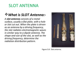
Downloaded 794 times


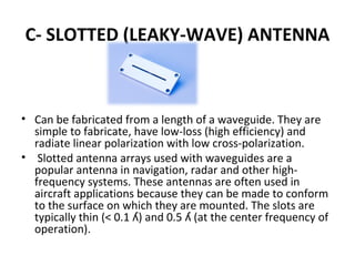
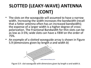
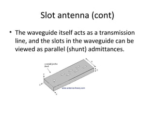
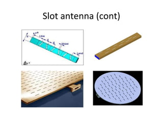
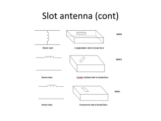
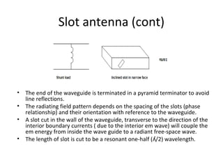


A slotted antenna array uses slots cut into a metal waveguide to radiate electromagnetic waves. The slots are typically thin and about half the wavelength of the center frequency. As waves propagate through the waveguide, the slots disturb the current and cause it to radiate linearly polarized waves with low cross-polarization. Slotted antenna arrays are commonly used in aircraft and other applications because they can conform to surfaces and are simple and efficient to fabricate. Multiple slots can be cut into the waveguide in a periodic pattern to form an antenna array. The position and size of the slots determine the radiation pattern produced.


