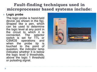
Fault Finding
Fault detection techniques, common hardware faults
Fault detection techniques
There are a number of techniques that can be used to
detect faults:
Fault detection techniques
 Replication Checks
This involves duplicating or replicating an
activity and comparing the results. In
absence of faults it is assumed that the
results should be the same. It could mean,
with transient errors, just repeat an
operation twice and comparing the results
or it could involve having duplicate
systems and comparing the results given
by the two. This can be an expensive
option.
Fault detection techniques
 Expected value checks
Software errors are commonly detected by checking
whether an expected value is obtained when a specific
numerical input is used. If the expected value is not
obtained then there is a fault.
 Timing checks
This involves the use of timing checks that some function
has been carried out within a specified time. These
checks are commonly referred to as Watchdog timers.
For example, with a PLC, when an operation starts a
timer is also started and if the operation is not completed
within the specified time a fault is assumed to have
occurred. The watchdog timer trips, sets off an alarm and
closes down part or the entire plant.
Fault detection techniques
 Reversal checks
Where there is a direct relationship between input
and output values, the value of the output can be
taken and the input which should have caused it
computed. This can then be compared with the
actual input.
 Diagnostic checks
Diagnostic checks are used to test the behavior of
components in a system. Input s are applied to a
component and the outputs compared with those
which should occur.
Fault detection techniques
 Parity and error coding checks
This form of checking is commonly used for
detecting memory and data transmission errors.
Communication channels are frequently subjected to
interference which can affect data being transmitted.
To detect whether data has been corrupted a parity
bit is a bit added to the transmitted data word. The
parity bit is chosen to make the resulting number of
1s in the group either odd (odd parity) or even (even
parity). If odd parity then the word can be checked
after transmission to see if it is still odd. Other forms
of checking involve codes added to transmitted data
in order to detect corrupt bits.
Common hardware faults
The following are some of the commonly encountered
faults that can occur with specific types of components
and systems.
Common hardware faults
 Sensors
If there are faults in a measurement system then the
sensor might be at fault. A simple test is to substitute
the sensor with a new one and see what effect this
has on the results given by the system. If the results
change then it is likely that the original sensor was
faulty; if the results do not change then the fault is
elsewhere in the system. It is also possible to check
that the voltage/current sources are supplying the
correct voltages/currents, whether there is electrical
continuity in connecting wires, that the sensor is
correctly mounted and used under the conditions
specified by the manufacturer’s data sheet, etc.
Common hardware faults
 Switches and relay
Dirt and particles of waste material between switch contacts is a
common source of incorrect functioning of mechanical switches.
A voltmeter used across a switch should indicate the applied
voltage when the contacts are open and nearly zero when they
are closed.
 Motors
Maintenance of both DC and AC motors involves correct
lubrication. With DC motors the brushes wear and can require
changing. Setting of new brushes needs to be in accordance
with the manufacturer’s specification. A single-phase capacitor
start AC motor that is sluggish in starting probably needs a new
starting capacitor.
Three-phase induction motor has no brushes, commutator, slip
rings or starting capacitor and short of a severe overload, the
only regular maintenance that is required is periodic lubrication.
 Hydraulic and pneumatic systems
Common cause of faults with hydraulic and pneumatic
systems is dirt. Small particles of dirt can damage seals,
block orifices, cause valve spools to jam, etc. thus filters
should be regularly checked and cleaned, components
should only be dismantled in clean conditions, and oil
should be regularly checked and changed.
Damaged to seals can result in hydraulic and pneumatic
cylinders leaking, beyond that which is normal, and result
in a drop in system pressure when the cylinder is
actuated. This can be remedied by replacing the seals in
the cylinders.
The vane in vane-type motors are subject to wear and
can then fail to make a good seal with the motor housing
with the result of a loss of motor power. The vanes can
be replaced. Leaks in hoses, pipes and fitting are
Common hardware faults
Microprocessor system
Typical faults in microprocessor systems are:
Faults in microprocessor systems
 Chip failure
 Chips are fairly reliable but occasionally there can be
failure

 Passive component failure
 Microprocessor systems will usually include passive
components such as resistors and capacitors. Failure of
any of these can cause system malfunction.

 Open circuits
 Open circuit can result in a break in a signal path or in a
power line. Typical reasons for such faults are
unsoldered or faulty soldered joints, fracture of printed
circuit track, a faulty connection on a connector and
breaks in cables.
 Short circuits
 Short circuits between points on a board which
should not be connected often arise as a result of
surplus solder bridging the gap between
neighbouring printed circuit tracks.

 Software faults
 Despite extensive testing it is still quite feasible for
software to contain bugs and under particular input
or output conditions cause a malfunction.
Faults in microprocessor systems
Fault-finding techniques in
Microprocessor based system
Fault-finding techniques used in
microprocessor based systems include:
 Visual inspection
Just carefully looking at faulty system may reveal the
source of a fault, e.g. an integrated circuit which is
loose in its holder or surplus solder bridging tracks
on a board.
 Multimeter
This is of limited use with microprocessor systems
but can be used to check for short- or open-circuit
connections and the power supplies.
 Logic probe
The logic probe is hand-held
device (as shown in the fig).
Shaped like a pen, which
can be used to determine
the logic level at any point in
the circuit to which it is
connected. The selector
switch is set for TTL or
CSMOS operations and
when the probe tip is
touched to the point of
question, the indicator lamp
indicates whether it is below
the logic level 0 thresholds,
above the logic 1 threshold
or pulsating signal.
Fault-finding techniques used in
microprocessor based systems include:
 Logic pulser
The logic pulser is a hand-
held pulse generator,
shaped like a pen that is
used to inject controlled
pulses into circuits. The
pulse probe tip is pressed
against a node in the
circuit and the button on
the probe pressed to
generate pulse. It is often
used with the logic probe
to check the functions of
logic gates.
Fault-finding techniques used in
microprocessor based systems include:
 Current tracer
The current tracer is similar to the logic probe but it
senses pulsing current in a circuit rather than voltage
levels. The tip of the current tracer is magnetically
sensitive and is used to detect the changing
magnetic field near conductor carrying a pulsing
current. The current tracer tip is moved along printed
circuit tracks to trace out the low-impendence paths
along which current is flowing
Fault-finding techniques used in
microprocessor based systems include:
Questions
Wishing you all the best

Fault Finding.pptx

  • 1.
    Fault Finding Fault detectiontechniques, common hardware faults
  • 2.
    Fault detection techniques Thereare a number of techniques that can be used to detect faults:
  • 3.
    Fault detection techniques Replication Checks This involves duplicating or replicating an activity and comparing the results. In absence of faults it is assumed that the results should be the same. It could mean, with transient errors, just repeat an operation twice and comparing the results or it could involve having duplicate systems and comparing the results given by the two. This can be an expensive option.
  • 4.
    Fault detection techniques Expected value checks Software errors are commonly detected by checking whether an expected value is obtained when a specific numerical input is used. If the expected value is not obtained then there is a fault.  Timing checks This involves the use of timing checks that some function has been carried out within a specified time. These checks are commonly referred to as Watchdog timers. For example, with a PLC, when an operation starts a timer is also started and if the operation is not completed within the specified time a fault is assumed to have occurred. The watchdog timer trips, sets off an alarm and closes down part or the entire plant.
  • 5.
    Fault detection techniques Reversal checks Where there is a direct relationship between input and output values, the value of the output can be taken and the input which should have caused it computed. This can then be compared with the actual input.  Diagnostic checks Diagnostic checks are used to test the behavior of components in a system. Input s are applied to a component and the outputs compared with those which should occur.
  • 6.
    Fault detection techniques Parity and error coding checks This form of checking is commonly used for detecting memory and data transmission errors. Communication channels are frequently subjected to interference which can affect data being transmitted. To detect whether data has been corrupted a parity bit is a bit added to the transmitted data word. The parity bit is chosen to make the resulting number of 1s in the group either odd (odd parity) or even (even parity). If odd parity then the word can be checked after transmission to see if it is still odd. Other forms of checking involve codes added to transmitted data in order to detect corrupt bits.
  • 7.
    Common hardware faults Thefollowing are some of the commonly encountered faults that can occur with specific types of components and systems.
  • 8.
    Common hardware faults Sensors If there are faults in a measurement system then the sensor might be at fault. A simple test is to substitute the sensor with a new one and see what effect this has on the results given by the system. If the results change then it is likely that the original sensor was faulty; if the results do not change then the fault is elsewhere in the system. It is also possible to check that the voltage/current sources are supplying the correct voltages/currents, whether there is electrical continuity in connecting wires, that the sensor is correctly mounted and used under the conditions specified by the manufacturer’s data sheet, etc.
  • 9.
    Common hardware faults Switches and relay Dirt and particles of waste material between switch contacts is a common source of incorrect functioning of mechanical switches. A voltmeter used across a switch should indicate the applied voltage when the contacts are open and nearly zero when they are closed.  Motors Maintenance of both DC and AC motors involves correct lubrication. With DC motors the brushes wear and can require changing. Setting of new brushes needs to be in accordance with the manufacturer’s specification. A single-phase capacitor start AC motor that is sluggish in starting probably needs a new starting capacitor. Three-phase induction motor has no brushes, commutator, slip rings or starting capacitor and short of a severe overload, the only regular maintenance that is required is periodic lubrication.
  • 10.
     Hydraulic andpneumatic systems Common cause of faults with hydraulic and pneumatic systems is dirt. Small particles of dirt can damage seals, block orifices, cause valve spools to jam, etc. thus filters should be regularly checked and cleaned, components should only be dismantled in clean conditions, and oil should be regularly checked and changed. Damaged to seals can result in hydraulic and pneumatic cylinders leaking, beyond that which is normal, and result in a drop in system pressure when the cylinder is actuated. This can be remedied by replacing the seals in the cylinders. The vane in vane-type motors are subject to wear and can then fail to make a good seal with the motor housing with the result of a loss of motor power. The vanes can be replaced. Leaks in hoses, pipes and fitting are Common hardware faults
  • 11.
    Microprocessor system Typical faultsin microprocessor systems are:
  • 12.
    Faults in microprocessorsystems  Chip failure  Chips are fairly reliable but occasionally there can be failure   Passive component failure  Microprocessor systems will usually include passive components such as resistors and capacitors. Failure of any of these can cause system malfunction.   Open circuits  Open circuit can result in a break in a signal path or in a power line. Typical reasons for such faults are unsoldered or faulty soldered joints, fracture of printed circuit track, a faulty connection on a connector and breaks in cables.
  • 13.
     Short circuits Short circuits between points on a board which should not be connected often arise as a result of surplus solder bridging the gap between neighbouring printed circuit tracks.   Software faults  Despite extensive testing it is still quite feasible for software to contain bugs and under particular input or output conditions cause a malfunction. Faults in microprocessor systems
  • 14.
  • 15.
    Fault-finding techniques usedin microprocessor based systems include:  Visual inspection Just carefully looking at faulty system may reveal the source of a fault, e.g. an integrated circuit which is loose in its holder or surplus solder bridging tracks on a board.  Multimeter This is of limited use with microprocessor systems but can be used to check for short- or open-circuit connections and the power supplies.
  • 16.
     Logic probe Thelogic probe is hand-held device (as shown in the fig). Shaped like a pen, which can be used to determine the logic level at any point in the circuit to which it is connected. The selector switch is set for TTL or CSMOS operations and when the probe tip is touched to the point of question, the indicator lamp indicates whether it is below the logic level 0 thresholds, above the logic 1 threshold or pulsating signal. Fault-finding techniques used in microprocessor based systems include:
  • 17.
     Logic pulser Thelogic pulser is a hand- held pulse generator, shaped like a pen that is used to inject controlled pulses into circuits. The pulse probe tip is pressed against a node in the circuit and the button on the probe pressed to generate pulse. It is often used with the logic probe to check the functions of logic gates. Fault-finding techniques used in microprocessor based systems include:
  • 18.
     Current tracer Thecurrent tracer is similar to the logic probe but it senses pulsing current in a circuit rather than voltage levels. The tip of the current tracer is magnetically sensitive and is used to detect the changing magnetic field near conductor carrying a pulsing current. The current tracer tip is moved along printed circuit tracks to trace out the low-impendence paths along which current is flowing Fault-finding techniques used in microprocessor based systems include:
  • 19.