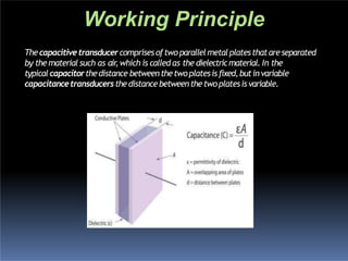
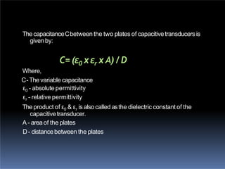
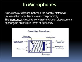
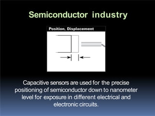
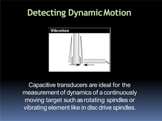
CAPACITIVE
TYPE
TRANSDUCERS
Introduction
Work Principle
Parameters of capacitive transducer
Application of capacitive transducer
Advantages and Disadvantages
Introduction
“Capacitive type means using capacitance and
transducer means a device thatconverts variations
ina physical quantity,intoan electricalsignal”
 Moreover, the capacitive transducer or
sensoris nothing but the capacitor with
variable capacitance
Thecapacitivetransducercomprisesoftwoparallelmetalplatesthatareseparated
by thematerial such as air,which is called as the dielectricmaterial. In the
typical capacitorthedistance betweenthetwoplatesisfixed,butinvariable
capacitancetransducersthedistancebetweenthetwoplatesisvariable.
Working Principle
ThecapacitanceCbetween the two plates of capacitivetransducersis
givenby:
C= (ε0 xεr x A) /D
Where,
C-Thevariable capacitance
ε0 - absolute permittivity
εr - relative permittivity
Theproduct of ε0 & εr is alsocalled asthe dielectric constant of the
capacitivetransducer.
A - areaof the plates
D- distancebetween the plates
Parameters of Capacitive
transducers
 Changing Dielectric Constant type of
Capacitive Transducers
 Changing Area of the Plates of Capacitive
Transducers
 Changing Distance between the Plates of
Capacitive Transducers
Changing Dielectric Constant
type of Capacitive Transducers
In these capacitive transducer the dielectric material between
the two plates changes, due to which the capacitance of the
transducer also changes. When the input quantity to be
measured changes the value of the dielectric constant also
changes so the capacitance of the instrument changes. This
capacitance, calibrated against the input quantity, directly
gives the value of the quantity to be measured. This principle
is used for measurement of level in the hydrogen container,
where the change in level of hydrogen between the two plates
results in change of the dielectric constant of the capacitance
transducer. Apart from level, this principle can also be used for
measurement of humidity and moisture content of the air.
Changing Area of the Plates of
Capacitive Transducers
The capacitance of the variable capacitance
transducer also changes with the area of the
two plates. This principle is used in the
torquemeter, used for measurement of the
torque on the shaft. This comprises of the
sleeve that has teeth cut axially and the
matching shaft that has similar teeth at its
periphery.
Changing Distance between the
Plates of Capacitive Transducers
In these capacitive transducers the distance between the
plates is variable, while the area of the plates and the dielectric
constant remain constant. This is the most commonly used
type of variable capacitance transducer. For measurement of
the displacement of the object, one plate of the capacitance
transducer is kept fixed, while the other is connected to the
object. When the object moves, the plate of the capacitance
transducer also moves, this results in change in distance
between the two plates and the change in the capacitance.
The changed capacitance is measured easily and it calibrated
against the input quantity, which is displacement. This
principle can also be used to measure pressure, velocity,
acceleration etc.
Capacitive type transducers has wide range of applications in
which some of them are:
 In Microphones
 In SemiconductorIndustries
 In Detecting DynamicMotion
Application of Capacitive
transducer
In Microphones
An increase of distance between the parallel plates will
decrease the capacitance valuecorrespondingly.
This transduceris usedto convert the value of displacement
or change in pressurein terms of frequency.
•As shown in the figure ,A capacitive transducer has a
static plate and a deflected flexible diaphragm with a
dielectricinbetween.When a forceis exertedtotheouter
side of the diaphragm the distance between the
diaphragm and thestaticplatechanges.This produces a
capacitance which is measured using an alternating
currentbridgeora tank circuit.
•A tank circuitismorepreferredbecauseitproduces a
change in frequency according to the change in
capacitance. This value of frequencywill be
corresponding tothedisplacement orforcegiven tothe
input.
Capacitive sensors are used for the precise
positioning of semiconductor down to nanometer
level for exposure in different electrical and
electronic circuits.
Semiconductor industry
Capacitive transducers are ideal for the
measurement of dynamics of acontinuously
moving target such asrotating spindles or
vibrating element like in disc drive spindles.
Detecting DynamicMotion
 Liquid level measurement by changing the
capacitance between two conductive plates.
 Capacitors are common forcesensors.
 Commonly usedforThickness measurement in a
noncontact fashion.
Advantages
 High sensitivity
 Candetect upto 10-14 m displacements
 Low powerrequirement
 High resolution
 Low cost
 Easyto integrate into ICs
Disadvantages
 Performance is severelyeffected by dirt and
other contaminants.
 The metallic part must be insulated from
eachother.
 Affected by temperature and humidity
 Sensitivity to noise
 Difficulties indesigning
 Non-linearity
References
 www.electronicdesign.com
 www.instrumentationtoday.com
 http://www.brighthubengineering.com/hvac
/53147-how-capacitive-transducers-work/
 http://kalpanatamvada.tripod.com/
 https://circuitglobe.com/capacitive-
transducer.html
Capacitive type transducers

Capacitive type transducers

  • 1.
  • 2.
    Introduction Work Principle Parameters ofcapacitive transducer Application of capacitive transducer Advantages and Disadvantages
  • 3.
    Introduction “Capacitive type meansusing capacitance and transducer means a device thatconverts variations ina physical quantity,intoan electricalsignal”  Moreover, the capacitive transducer or sensoris nothing but the capacitor with variable capacitance
  • 4.
    Thecapacitivetransducercomprisesoftwoparallelmetalplatesthatareseparated by thematerial suchas air,which is called as the dielectricmaterial. In the typical capacitorthedistance betweenthetwoplatesisfixed,butinvariable capacitancetransducersthedistancebetweenthetwoplatesisvariable. Working Principle
  • 5.
    ThecapacitanceCbetween the twoplates of capacitivetransducersis givenby: C= (ε0 xεr x A) /D Where, C-Thevariable capacitance ε0 - absolute permittivity εr - relative permittivity Theproduct of ε0 & εr is alsocalled asthe dielectric constant of the capacitivetransducer. A - areaof the plates D- distancebetween the plates
  • 6.
    Parameters of Capacitive transducers Changing Dielectric Constant type of Capacitive Transducers  Changing Area of the Plates of Capacitive Transducers  Changing Distance between the Plates of Capacitive Transducers
  • 7.
    Changing Dielectric Constant typeof Capacitive Transducers In these capacitive transducer the dielectric material between the two plates changes, due to which the capacitance of the transducer also changes. When the input quantity to be measured changes the value of the dielectric constant also changes so the capacitance of the instrument changes. This capacitance, calibrated against the input quantity, directly gives the value of the quantity to be measured. This principle is used for measurement of level in the hydrogen container, where the change in level of hydrogen between the two plates results in change of the dielectric constant of the capacitance transducer. Apart from level, this principle can also be used for measurement of humidity and moisture content of the air.
  • 8.
    Changing Area ofthe Plates of Capacitive Transducers The capacitance of the variable capacitance transducer also changes with the area of the two plates. This principle is used in the torquemeter, used for measurement of the torque on the shaft. This comprises of the sleeve that has teeth cut axially and the matching shaft that has similar teeth at its periphery.
  • 9.
    Changing Distance betweenthe Plates of Capacitive Transducers In these capacitive transducers the distance between the plates is variable, while the area of the plates and the dielectric constant remain constant. This is the most commonly used type of variable capacitance transducer. For measurement of the displacement of the object, one plate of the capacitance transducer is kept fixed, while the other is connected to the object. When the object moves, the plate of the capacitance transducer also moves, this results in change in distance between the two plates and the change in the capacitance. The changed capacitance is measured easily and it calibrated against the input quantity, which is displacement. This principle can also be used to measure pressure, velocity, acceleration etc.
  • 10.
    Capacitive type transducershas wide range of applications in which some of them are:  In Microphones  In SemiconductorIndustries  In Detecting DynamicMotion Application of Capacitive transducer
  • 11.
    In Microphones An increaseof distance between the parallel plates will decrease the capacitance valuecorrespondingly. This transduceris usedto convert the value of displacement or change in pressurein terms of frequency.
  • 12.
    •As shown inthe figure ,A capacitive transducer has a static plate and a deflected flexible diaphragm with a dielectricinbetween.When a forceis exertedtotheouter side of the diaphragm the distance between the diaphragm and thestaticplatechanges.This produces a capacitance which is measured using an alternating currentbridgeora tank circuit. •A tank circuitismorepreferredbecauseitproduces a change in frequency according to the change in capacitance. This value of frequencywill be corresponding tothedisplacement orforcegiven tothe input.
  • 13.
    Capacitive sensors areused for the precise positioning of semiconductor down to nanometer level for exposure in different electrical and electronic circuits. Semiconductor industry
  • 14.
    Capacitive transducers areideal for the measurement of dynamics of acontinuously moving target such asrotating spindles or vibrating element like in disc drive spindles. Detecting DynamicMotion
  • 15.
     Liquid levelmeasurement by changing the capacitance between two conductive plates.  Capacitors are common forcesensors.  Commonly usedforThickness measurement in a noncontact fashion.
  • 16.
    Advantages  High sensitivity Candetect upto 10-14 m displacements  Low powerrequirement  High resolution  Low cost  Easyto integrate into ICs
  • 17.
    Disadvantages  Performance isseverelyeffected by dirt and other contaminants.  The metallic part must be insulated from eachother.  Affected by temperature and humidity  Sensitivity to noise  Difficulties indesigning  Non-linearity
  • 18.
    References  www.electronicdesign.com  www.instrumentationtoday.com http://www.brighthubengineering.com/hvac /53147-how-capacitive-transducers-work/  http://kalpanatamvada.tripod.com/  https://circuitglobe.com/capacitive- transducer.html