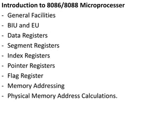
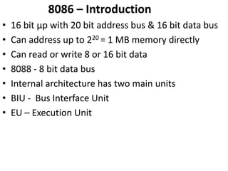
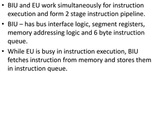
The document provides an overview of the 8086/8088 microprocessor architecture. It discusses the main components including the Bus Interface Unit (BIU) and Execution Unit (EU) that work in parallel to implement a two-stage pipeline. It describes the various registers like the segment, index, pointer, and flag registers. It also covers the different addressing modes used to calculate physical memory addresses from segment and offset values in real mode.
1. Introduction to 8086/8088 Microprocesser
- General Facilities
- BIU and EU
- Data Registers
- Segment Registers
- Index Registers
- Pointer Registers
- Flag Register
- Memory Addressing
- Physical Memory Address Calculations.
2. 8086 – Introduction
• 16 bit µp with 20 bit address bus & 16 bit data bus
• Can address up to 220 = 1 MB memory directly
• Can read or write 8 or 16 bit data
• 8088 - 8 bit data bus
• Internal architecture has two main units
• BIU - Bus Interface Unit
• EU – Execution Unit
3.
4. • BIU and EU work simultaneously for instruction
execution and form 2 stage instruction pipeline.
• BIU – has bus interface logic, segment registers,
memory addressing logic and 6 byte instruction
queue.
• While EU is busy in instruction execution, BIU
fetches instruction from memory and stores them
in instruction queue.
5. • If EU executes a jump instruction
– Program control to be transferred to another location
then BIU
• Resets the queue
• Fetches instruction from new address
• Passes the instruction to EU
• Starts refilling the queue from new location
• Process is called pipeline flushing.
6. BIU of 8088
• 8088 – 4 byte instruction queue
• Each time there is empty space of 2 bytes or more
8086 BIU startes filling the queue.
• 8088 BIU fills the queue when there is empty space
of 1 byte.
7. Execution Unit (EU)
• Contains – instruction decoder, ALU, general purpose
registers, pointer registers, index registers, flag register
and control circuitary to execute instruction.
• EU is resposible for-
– Execution of instructions
– Providing address to BIU for fetching
data/instruction.
– Manipulating various registers as well as flag register.
• EU is almost completly isolated from outside world.
• BIU performs all bus operations for EU.
• Overlapped fetching and execution of instruction is
shown
8.
9. It is assumed that
• Two µps i.e 2nd generation and 8086 execute the
instruction in same no. of clock cycles.
• Due to overlapping of fetch and excute, 8086/8088
is able to excute 3 instruction in lesser time but also
able to fetch 4th and 5th instruction.
• Register Set- 8086 has fourteen – 16 bit registers
• Data Registers
• Segment Registers
• Pointer & index register
• flag register
10.
11. • Data Registers- Four sixteen bit AX,BX,CX,DX
• Or 8 – 8 bit registers
• AH AL BH BL CH CL DH DL
• AX- Primary Accumulator
• Input-Output operations through AX(or AL)
• Several string operations require one operand
to be in AX (or AL).
• 16 bit divide or multiply - AX has one word
operand (AL for 8 bit operation).
• 32 bit multiply or divide – AX holds lower order
word operand.
12.
13. • BX – GPR (Genral Purpose Register) + Base Register
• CX – GPR + Count Register in multi iteration
instruction.
• DX – GPR + used in I/O instructions, multiply
& divide instructions.
14.
15. Segment Registers
• concept of memory segmentation.
Memory divided into no. of parts called segments.
• In 8086, 1 MB physical memory can be divide into 4
types of segments.
• Starting address of each segment is placed in 16 bit
register
• CS – Code Segment Register.
• DS – Data Segment Register.
• SS – Stack Segment Register.
• ES – Extra Segment Register.
• Each segment has memory space of 64k byte
16.
17.
18. Index Registers
SI – Source Index Register
DI – Destination Index Register
• May be used as GPR. However main purpose is to
store address offset in case of – Indexed, Base
Indexed, and Relative Base Indexed addressing
modes
19.
20. Pointer Registers
• Stack Pointer(SP) - provides access to stack top.
Holds offset address of stack top.
• Instruction Pointer(IP) - holds offset address of next
instruction to be executed. Like program counter.
• Base Pointer (BP) - GPR. Main purpose is to provide
indirect access to data in stack.
21.
22. • Flag Register - also called program status word
(PSW)
9 active Flags
6 status flags
3 control flags
23.
24. Status Flag –
• Carry – Arithmetic operation results is carry out of
MSB or Borrow in Subtraction. Also used in shift &
Rotate.
• Parity – Even parity in byte operation or lower byte
of word operation
• Auxiliary Carry – set if there in carry out of lower
nibble to higher nibble in 8 bit quantity or lower
byte to higher byte in 16 bit quantity. Used in BCD
operations.
• Zero – set when result of operation is zero.
25. • Sign – set when after arithmetic or logic
operation, MSB of result = 1 indicates that result is
negative.
• Overflow – used to detect magnitude overflow in
signed arithmetic.
• For addition operation – flag is set when there
is carry in to MSB but no carry out of MSB or
vice versa.
• For subtraction – flag is set when MSB needs a
borrow but there is no borrow from MSB or
vice versa.
26. Control Flags –
• Direction – Used with string operations. When set
(i.e = 1) then string operation in auto decrement
mode (i.e right to left) when reset (i.e = 0) then
string operation in auto increment mode (left to
right)
Interrupt Enable –
• When = 1, enables 8086 to recognize external
interrupts. When = 0, all maskable interrupts are
disabled. No effect on non maskable interrupts.
• Trap flag – when = 1, sets processor in single step
mode for debugging.
27. Memory Addressing – Real Mode
• Real Mode – limited to 1 MB of memory i.e real
memory.
• Segment Register – 16 bits in length.
• Memory address – 20 bits.
• Segment register content are appended with 0000 to
make it 20 bit address i.e segment register contents are
multiplied by 16
• Now the address represent the starting address of
segment in memory
• Let us say CS = 1234H
• After appending with 0000(=0H) we get 12340H as
starting address of code segment in memory.
• The size of a segment i.e 64kb i.e FFFFH
• The address range of code segment 12340H to (12340
+ FFFF) = 2233FH
28.
29. • A segment must thus start at 16 byte boundary
[since last 4 bits = 0000]
• Two segment can overlap with each other partially
if segment address have been defined like that.
• There may be more then one segment of a
particular type. For that segment register contents
are dynamically changed.
• All real mode memory addresses consist of segment
address plus an offset address.
• Offset address – increment from starting of
segment.
30. • Thus segment address defines the starting address
of 64k byte memory segment.
• Offset address selects a location within 64k byte
memory segment.
• Offset address is also known as logical address.
• Physical address is actual memory location of
operands = segment address appended with 0H +
offset address = (segment address) x 16 + offset
address.
31.
32. - Let us take an example.
-> Segment register = 1234H
-> Offset = 0022H
Physical address ?
Segment starting address = 12340H
+ offset = 0022H
________________________
Physical address = 12362H
Exercise 1 – calculate last address of segment, given
the segment register values as 1234H, 2300H and
AB00H.
33.
34. Exercise -2 – Given physical address of memory
location and segment register content, find the
logical address i.e offset
35.
36.
37. Note –
• 8086 and 8088 operate only in real mode
• 80286 – 80486 – Pentium – operate in real or
protected mode.
• Real mode operation allows microprocessor to
address only first 1 MB of memory space even if it is
80486 µp.
• Memory segmentation allows program to be
relocated in any portion of memory.
38. • There is a set combination of segment register and
offset register known as default combination .
Segment offset Special purpose
CS IP Instruction address
SS SP or BP stack address
DS BX,DI,SI Data address
An 8 or 16 bit number
ES DI for string string destination
instruction address