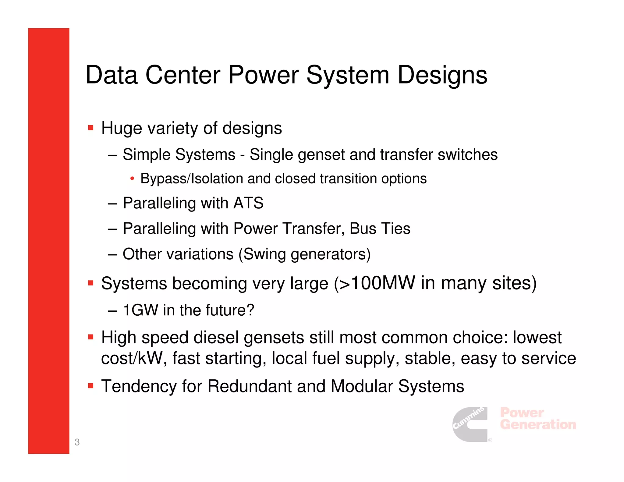
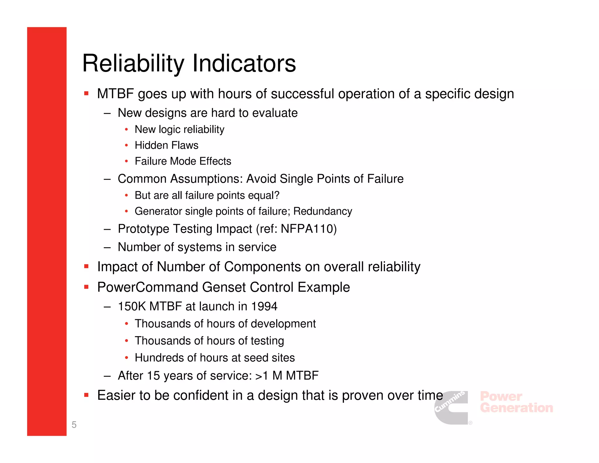
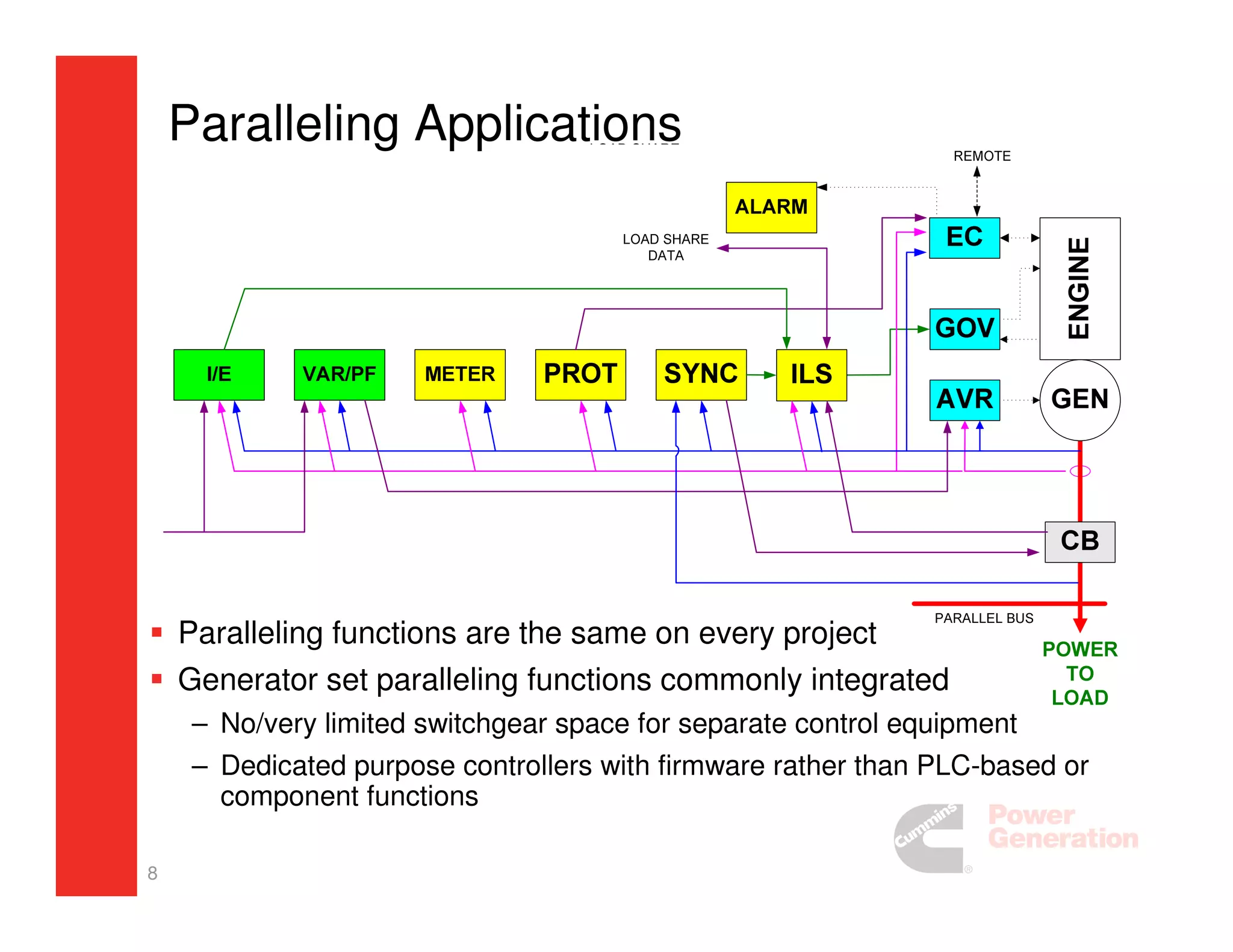
1. Evaluation of
Large Standby Power System
Architectures
As facility power needs get very large, what’s the best
design for optimum reliability?
2. 2
Agenda
Current Trends on Data Centers Design
Reliability Indicators
Overview of System Designs
Lessons Learned
Conclusions and Take-aways
3. 3
Data Center Power System Designs
Huge variety of designs
– Simple Systems - Single genset and transfer switches
• Bypass/Isolation and closed transition options
– Paralleling with ATS
– Paralleling with Power Transfer, Bus Ties
– Other variations (Swing generators)
Systems becoming very large (>100MW in many sites)
– 1GW in the future?
High speed diesel gensets still most common choice: lowest
cost/kW, fast starting, local fuel supply, stable, easy to service
Tendency for Redundant and Modular Systems
4. 4
Big is not necessarily complex…
Long Island Power Demand Response Site
– 48MW, each machine individually paralleled to grid, controlled by SCADA software
– Emissions compliant
– No switchgear or additional controls required
5. 5
Reliability Indicators
MTBF goes up with hours of successful operation of a specific design
– New designs are hard to evaluate
• New logic reliability
• Hidden Flaws
• Failure Mode Effects
– Common Assumptions: Avoid Single Points of Failure
• But are all failure points equal?
• Generator single points of failure; Redundancy
– Prototype Testing Impact (ref: NFPA110)
– Number of systems in service
Impact of Number of Components on overall reliability
PowerCommand Genset Control Example
– 150K MTBF at launch in 1994
• Thousands of hours of development
• Thousands of hours of testing
• Hundreds of hours at seed sites
– After 15 years of service: >1 M MTBF
Easier to be confident in a design that is proven over time
6. 6
A GOOD QUESTION
OK, it’s easy to see that reliability is positively
impacted by consistent quality control on a lot of
widgits,
but how do we deal with large, complex “one of a
kind” systems?
7. 7
Simplest Designs
Genset with one or more ATS
– Best for smaller projects
– Can be multiplied for larger projects
Genset operating power transfer
breaker pair
– Best for larger generators, switching
near service
– Lowest cost, smallest footprint
– Can synchronize and ramp loads
between live sources
– Breakers can trip, so need to deal
with that logically
– Can be multiplied for any size
project
When used in multiples, each
genset/transfer equipment has single
points of failure, but only part of
system fails
8. 8
Paralleling Applications
Paralleling functions are the same on every project
Generator set paralleling functions commonly integrated
– No/very limited switchgear space for separate control equipment
– Dedicated purpose controllers with firmware rather than PLC-based or
component functions
9. 9
Parallel Applications
Paralleling Systems Utilize Major
Control Blocks with Common Functions
– Parallel Controllers (PLL)
• Start/Stop/Protect Genset
• Black Start Control
• Synchronize
• Load Share
• Bus Protection
– Transfer Controllers (ATS)
• Source Availability
• Transfer Logic
– System Control
• System monitoring
• Load Management (load add/shed)
• Capacity Management (load demand)
Distributed Logic Strategy
Design Control
– “One Throat to Choke”
10. 10
Isolated Bus Master Control Functions
Load Management (load add & shed sequence)
– Back-up for overide of automatic sequence
– Controls feeder breakers, ATS, or interface to BMS
System Capacity (load demand)
– Provides means of minimizing fuel consumption in long runs
Local Operator Interface
– What do you want the operator to do? Where?
Remote Monitor & Control
Digital Control
11. 11
Remote Monitoring & Control
! "# $
$
%
& $' ()
*
! "# $
$
%
& $' ()
*
%
Multiple Networks/Multiple Uses
– Isolated for speed, ease of installation
Remote Monitoring is Very Common
– Tons of data and control is available
13. 13
More Complex Designs
%
A combination of core paralleling and power transfer control
blocks
May have many generators and many transfer pairs
Common to have multiple feeds to downstream devices
Usually includes a central monitoring system for entire
package
14. 14
Impact of Automated Ties
Automating Tie
operation
complicates design
Best accomplished
with core controls,
orchestrated with
PLC
Best practice is
to exercise
design control
on PLC logic
“modules”
16. 16
Tier 3 Data Center Design
More duplicated functions…
PARALLELING
PWR TRANS
17. 17
Lessons Learned:
Effective Use of Redundancy
Single points of failure have a big impact on
reliability
Address by:
– Design it out
– True Redundancy
– Live with it/Best Quality
Genset Example
MasterControl Example
18. 18
Lessons Learned:
Support for Complex Systems
Look for ability to have support local to the project site
– Local support should be equipped with software necessary for
PLC and HMI (if different)
– Training is critical
Consider ability to support the PLC and HMI and other
controls’ software in the future
– 30-year life is not unexpected at many sites
– Vendors’ commitment to backward compatibility
• This capability varies with vendor
– Number of software sets needed for total service is a major
concern over time
19. 19
Lessons Learned:
Hot Standby (Vendor 1) + Hot Standby (Vendor 2)
What does “Redundant PLC” mean?
– Redundant Processor? Redundant I/O? Redundant Power
Supply? Redundant Power Supply Bus? Redundant Coms
Links?
Hot Standby practices can significantly impact PLC operation
time (responsiveness)
– Impact on display responsiveness
– Operation time for critical functions
Capabilities of each PLC/Touchscreen differ by vendor
– Every system supplier standardizes on specific vendors, and has
limited flexibility to use others
20. 20
Lessons Learned:
On-going Operator Instruction & Training
Posted Manual Operation Instructions
– Consider all critical operations,
• power transfer from utility to gensets and return
• gensets on and off bus (if paralleled)
• manual load add and shed
Pay Attention to Operator Panel Information
– What are operator capabilities?
– What do you want them to do?
– Where do you want them to do it?
21. 21
Conclusions
There’s a lot of wisdom in the first rule of
engineering: KISS
BUT, we are dealing with complicated facilities and
demanding performance requirements
Use Distributed Logic Strategy
Make sure of support plan in the long run
Keep learning from experience
23. 23
Product Configurations
Cummins Caterpillar/Asco4000 Generac
This slide shows the genset and paralleling control functions for
different suppliers
Cat/Asco/Generac all have 6-8 level load add/shed and load demand
in their arrangement
– Most global control competitors use the Cat/Asco model, except SDMO