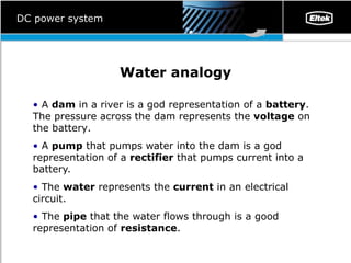
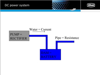
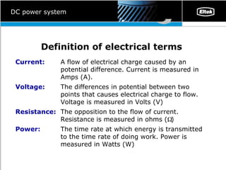
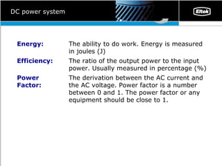
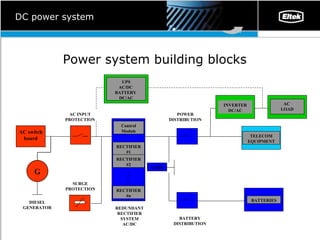
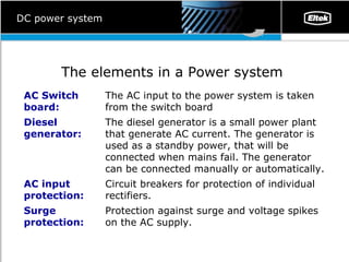
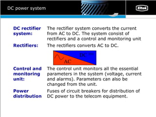
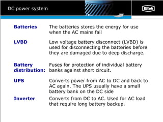
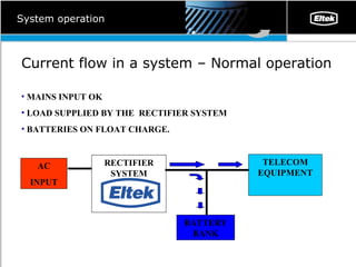
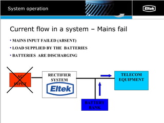
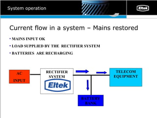
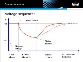
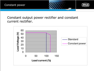
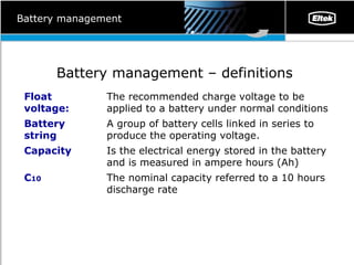
DC power system training The purpose of this presentation is to give an introduction to DC power systems and DC power fundamentals. DC Power System
Scope of training Why do we user DC power ? DC system – Water analogy   Definition of electrical terms   Electrical basic equations   DC power system –    Elements and fundamental operation   Battery management   DC power system
Why DC Power ? Provide a reliable power supply for telecom industry.  Telecom equipment must operate when AC supply is absent.  DC energy can be stored on batteries and used when AC power is absent.  A DC power system is 100% uninterruptible.  The DC power supply is a filter for noise (EMC, surge etc) that is present on the mains supply.  DC power system
Water analogy A  dam  in a river is a god representation of a  battery . The pressure across the dam represents the  voltage  on the battery .   A  pump  that pumps water into the dam is a god representation of a  rectifier  that pumps current into a battery.  The  water  represents the  current  in an electrical circuit.  The  pipe  that the water flows through is a good representation of  resistance .  DC power system
DC power system PUMP = RECTIFIER DAM = BATTERY Pipe  =  Resistance Water  =  Current
Definition of electrical terms   DC power system The time rate at which energy is transmitted to the time rate of doing work. Power is measured in Watts (W) Power: The opposition to the flow of current. Resistance is measured in ohms (  ) Resistance:  The differences in potential between two points that causes electrical charge to flow. Voltage is measured in Volts (V) Voltage: A flow of electrical charge caused by an potential difference. Current is measured in Amps (A). Current:
DC power system The derivation between the AC current and the AC voltage. Power factor is a number between 0 and 1. The power factor or any equipment should be close to 1.  Power Factor: The ratio of the output power to the input power. Usually measured in percentage (%) Efficiency: The ability to do work. Energy is measured in joules (J) Energy:
Electrical basic equations   Ohms law :  Voltage = Current x Resistance Power calculation : Power = Voltage x Current Energy calculation : Energy = Power x time DC power system
DC power system P ower system building blocks SURGE PROTECTION POWER DISTRIBUTION LVBD BATTERY DISTRIBUTION UPS AC/DC  BATTERY  DC/AC TELECOM EQUIPMENT BATTERIES INVERTER DC/AC AC  LOAD AC INPUT PROTECTION Control Module RECTIFIER #1 RECTIFIER #2 RECTIFIER #n REDUNDANT RECTIFIER SYSTEM AC/DC G DIESEL GENERATOR AC switch board
DC power system The elements in a Power system   P rotection against surge and voltage spikes on the AC supply.  Surge protection: Circuit breakers for protection of individual rectifiers.  AC input protection:  The diesel generator is a small power plant that generate AC current. The generator is used as a standby power, that will be connected when mains fail. The generator can be connected manually or automatically.  Diesel generator: The AC input to the power system is taken from the switch board AC Switch board:
DC power system Fuses of circuit breakers for distribution of DC power to the telecom equipment. Power distribution The control unit monitors all the essential parameters in the system (voltage, current and alarms). Parameters can also be changed from the unit.  Control and monitoring unit:  The rectifiers converts AC to DC. Rectifiers: The rectifier system converts the current from AC to DC. The system consist of rectifiers and a control and monitoring unit  DC rectifier  system: AC DC
DC power system Converts from DC to AC. Used for  AC  load that require long battery backup.  Inverter Converts power from AC to DC and back to AC again. The UPS usually have a small battery bank on the DC side UPS Fuses for protection o f  individual battery banks against short circuit.  Battery distribution: Low voltage battery disconnect (LVBD) is used for disconnecting the batteries before the y  are damaged due to deep discharge.  LVBD The batteries stores the energy for use when the AC mains fail Batteries
System operation Current flow in a system – Normal operation MAINS INPUT OK LOAD SUPPLIED BY THE  RECTIFIER SYSTEM BATTERIES ON FLOAT CHARGE. RECTIFIER SYSTEM TELECOM EQUIPMENT BATTERY BANK AC INPUT
System operation Current flow in a system –  Mains fail MAINS INPUT FAILED (ABSENT) LOAD SUPPLIED BY THE  BATTERIES BATTERIES  ARE DISCHARGING RECTIFIER SYSTEM TELECOM EQUIPMENT BATTERY BANK AC INPUT
System operation Current flow in a system –  Mains restored MAINS INPUT OK LOAD SUPPLIED BY THE  RECTIFIER SYSTEM BATTERIES  ARE RECHARGING RECTIFIER SYSTEM TELECOM EQUIPMENT BATTERY BANK AC INPUT
System operation U 54.5 43.2 Float charge Battery discharge Battery recharge t - - -  w/current limitation Disconnect Voltage Voltage sequence: Mains failure Mains resume
Constant output power Modern telecom equipment behaves as a constant power load A constant power rectifier system will regulate the voltage – current ratio to give constant power  output . Constant power rectifiers will a increased recharge capacity for the batteries ( 15- 20%) .   Constant power
Constant power Constant output power rectifier and constant current rectifier.
Battery management Battery management – definitions  The nominal capacity referred to a 10 hours discharge rate C 10 Is the electrical energy stored in the battery and is measured in ampere hours (Ah) Capacity A group of battery cells linked in series to produce the operating voltage.  Battery string The recommended charge voltage to be applied to a battery under normal conditions  Float voltage:
Battery management A technique that change the battery voltage as a function of battery temperature. This technique will increase the lifetime of the batteries and the rate of change is usually specified by the battery manufacturer Temperature compensation Is a voltage higher then the float voltage for fast charging or equalising of batteries Boost voltage A high voltage is applied to the batteries in order to equalise the cell voltage on a string of batteries Equalising batteries:
Battery management - why Ensure long lifetime of batteries . This is done by correct float voltage, temperature compensated charging and temperature controlled environment.  Prevent batteries form being damaged due to deep discharge . Low voltage battery disconnect is used to prevent deep discharge & damage to the load equipment Battery management
Battery management Open Circuit Voltage in relation to state of charge of the cell. 25 50 75 100 V DC 1.90 Open Circuit Voltage (per cell)l 1.95 2.00 2.05 2.10 2.15 0 State of charge (%)
Battery management Float Voltage versus temperature Temp (ºC) V DC 2.22 Volt per cell 2.24 2.26 2.28 2.30 2.32 2.34 2.36 2.38 -10 0 10 20 30 40
Battery management Battery capacity  versus temperature Temp (ºC) V DC 70 Available capacity  (%) 75 80 85 90 95 100 105 110 5 10 15 20 25 30

Dc Power System

  • 1.
    DC power systemtraining The purpose of this presentation is to give an introduction to DC power systems and DC power fundamentals. DC Power System
  • 2.
    Scope of trainingWhy do we user DC power ? DC system – Water analogy Definition of electrical terms Electrical basic equations DC power system – Elements and fundamental operation Battery management DC power system
  • 3.
    Why DC Power? Provide a reliable power supply for telecom industry. Telecom equipment must operate when AC supply is absent. DC energy can be stored on batteries and used when AC power is absent. A DC power system is 100% uninterruptible. The DC power supply is a filter for noise (EMC, surge etc) that is present on the mains supply. DC power system
  • 4.
    Water analogy A dam in a river is a god representation of a battery . The pressure across the dam represents the voltage on the battery . A pump that pumps water into the dam is a god representation of a rectifier that pumps current into a battery. The water represents the current in an electrical circuit. The pipe that the water flows through is a good representation of resistance . DC power system
  • 5.
    DC power systemPUMP = RECTIFIER DAM = BATTERY Pipe = Resistance Water = Current
  • 6.
    Definition of electricalterms DC power system The time rate at which energy is transmitted to the time rate of doing work. Power is measured in Watts (W) Power: The opposition to the flow of current. Resistance is measured in ohms (  ) Resistance: The differences in potential between two points that causes electrical charge to flow. Voltage is measured in Volts (V) Voltage: A flow of electrical charge caused by an potential difference. Current is measured in Amps (A). Current:
  • 7.
    DC power systemThe derivation between the AC current and the AC voltage. Power factor is a number between 0 and 1. The power factor or any equipment should be close to 1. Power Factor: The ratio of the output power to the input power. Usually measured in percentage (%) Efficiency: The ability to do work. Energy is measured in joules (J) Energy:
  • 8.
    Electrical basic equations Ohms law : Voltage = Current x Resistance Power calculation : Power = Voltage x Current Energy calculation : Energy = Power x time DC power system
  • 9.
    DC power systemP ower system building blocks SURGE PROTECTION POWER DISTRIBUTION LVBD BATTERY DISTRIBUTION UPS AC/DC BATTERY DC/AC TELECOM EQUIPMENT BATTERIES INVERTER DC/AC AC LOAD AC INPUT PROTECTION Control Module RECTIFIER #1 RECTIFIER #2 RECTIFIER #n REDUNDANT RECTIFIER SYSTEM AC/DC G DIESEL GENERATOR AC switch board
  • 10.
    DC power systemThe elements in a Power system P rotection against surge and voltage spikes on the AC supply. Surge protection: Circuit breakers for protection of individual rectifiers. AC input protection: The diesel generator is a small power plant that generate AC current. The generator is used as a standby power, that will be connected when mains fail. The generator can be connected manually or automatically. Diesel generator: The AC input to the power system is taken from the switch board AC Switch board:
  • 11.
    DC power systemFuses of circuit breakers for distribution of DC power to the telecom equipment. Power distribution The control unit monitors all the essential parameters in the system (voltage, current and alarms). Parameters can also be changed from the unit. Control and monitoring unit: The rectifiers converts AC to DC. Rectifiers: The rectifier system converts the current from AC to DC. The system consist of rectifiers and a control and monitoring unit DC rectifier system: AC DC
  • 12.
    DC power systemConverts from DC to AC. Used for AC load that require long battery backup. Inverter Converts power from AC to DC and back to AC again. The UPS usually have a small battery bank on the DC side UPS Fuses for protection o f individual battery banks against short circuit. Battery distribution: Low voltage battery disconnect (LVBD) is used for disconnecting the batteries before the y are damaged due to deep discharge. LVBD The batteries stores the energy for use when the AC mains fail Batteries
  • 13.
    System operation Currentflow in a system – Normal operation MAINS INPUT OK LOAD SUPPLIED BY THE RECTIFIER SYSTEM BATTERIES ON FLOAT CHARGE. RECTIFIER SYSTEM TELECOM EQUIPMENT BATTERY BANK AC INPUT
  • 14.
    System operation Currentflow in a system – Mains fail MAINS INPUT FAILED (ABSENT) LOAD SUPPLIED BY THE BATTERIES BATTERIES ARE DISCHARGING RECTIFIER SYSTEM TELECOM EQUIPMENT BATTERY BANK AC INPUT
  • 15.
    System operation Currentflow in a system – Mains restored MAINS INPUT OK LOAD SUPPLIED BY THE RECTIFIER SYSTEM BATTERIES ARE RECHARGING RECTIFIER SYSTEM TELECOM EQUIPMENT BATTERY BANK AC INPUT
  • 16.
    System operation U54.5 43.2 Float charge Battery discharge Battery recharge t - - - w/current limitation Disconnect Voltage Voltage sequence: Mains failure Mains resume
  • 17.
    Constant output powerModern telecom equipment behaves as a constant power load A constant power rectifier system will regulate the voltage – current ratio to give constant power output . Constant power rectifiers will a increased recharge capacity for the batteries ( 15- 20%) . Constant power
  • 18.
    Constant power Constantoutput power rectifier and constant current rectifier.
  • 19.
    Battery management Batterymanagement – definitions The nominal capacity referred to a 10 hours discharge rate C 10 Is the electrical energy stored in the battery and is measured in ampere hours (Ah) Capacity A group of battery cells linked in series to produce the operating voltage. Battery string The recommended charge voltage to be applied to a battery under normal conditions Float voltage:
  • 20.
    Battery management Atechnique that change the battery voltage as a function of battery temperature. This technique will increase the lifetime of the batteries and the rate of change is usually specified by the battery manufacturer Temperature compensation Is a voltage higher then the float voltage for fast charging or equalising of batteries Boost voltage A high voltage is applied to the batteries in order to equalise the cell voltage on a string of batteries Equalising batteries:
  • 21.
    Battery management -why Ensure long lifetime of batteries . This is done by correct float voltage, temperature compensated charging and temperature controlled environment. Prevent batteries form being damaged due to deep discharge . Low voltage battery disconnect is used to prevent deep discharge & damage to the load equipment Battery management
  • 22.
    Battery management OpenCircuit Voltage in relation to state of charge of the cell. 25 50 75 100 V DC 1.90 Open Circuit Voltage (per cell)l 1.95 2.00 2.05 2.10 2.15 0 State of charge (%)
  • 23.
    Battery management FloatVoltage versus temperature Temp (ºC) V DC 2.22 Volt per cell 2.24 2.26 2.28 2.30 2.32 2.34 2.36 2.38 -10 0 10 20 30 40
  • 24.
    Battery management Batterycapacity versus temperature Temp (ºC) V DC 70 Available capacity (%) 75 80 85 90 95 100 105 110 5 10 15 20 25 30