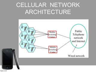
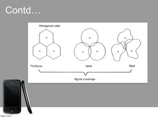
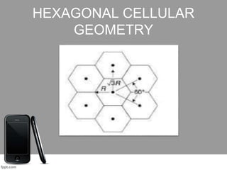
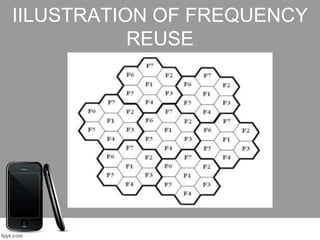
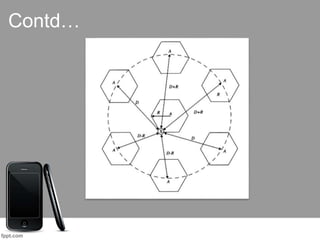
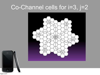
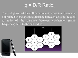
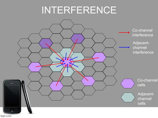
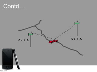
CELLULAR
CONCEPT
Divya Bansal
ECE 6TH Sem
110326105786
CELLULAR CONCEPT
• The cellular concept was a major breakthrough in solving
the problem of spectral congestion and user capacity.
• It offered very high capacity in a limited spectrum.
• Each cellular base station is allotted a group of radio
channels to be used within a small geographic area called
cells.
Contd…
• Use multiple low-power transmitters.
• Areas divided into cells
• Each served by its own antenna
• Served by base station consisting of
transmitter, receiver, and control unit
• Band of frequencies allocated
• Cells set up such that antennas of all neighbors
are equidistant (hexagonal pattern)
CELLULAR NETWORK
ARCHITECTURE
CELLS STRUCTURE
• Determined by the desired received signal level by
the mobile subscriber from its base station transmitter
in its operating area ideal, actual and fictitious cell
models.
Contd…
A CELL WITH A CS AND MOBILE
HEXAGONAL CELLULAR
GEOMETRY
• Offers best possible non-overlapped cell radio
coverage.
• Multiple hexagons can be arranged next to each other.
• The hexagons covers the large area.
• Simplifies the planning and design of the
cellular system.
HEXAGONAL CELLULAR
GEOMETRY
CELLULAR CLUSTER
• A group of cells that use a different set of frequencies
in each cell.
• Only selected number of cells can form a cluster.
• Can be repeated any number of times in a systematic
manner.
• The cluster size is the number of cells with in it and
designated by K.
HEXAGONALS CLUSTER
PATTERNS
CONVENTIONAL MOBILE
COMMUNICATION
• One very powerful transmitter located at the highest spot
in an area would broadcast in a radius of upto 50 kilometers.
LIMITATIONS:
• High power
consumption.
•Low capacity.
•Large size of the
mobile.
SYSTEM DESIGN PROBLEM
Main limitations of a conventional mobile
wireless communication system is:
• Minimum availability of FREQUENCY
SPECTRUM!!!
So the big challenge is…
to serve large no. of mobile users…
• within limited allocated frequency spectrum.
• with a specified system quality.
SYSTEM CAPACITY AND &
SPECTRUM UTILIZATION
How to increase the capacity and Spectrum
utilization
?
The Need:
• optimum spectrum usage
• More capacity
• High quality of service
• Low cost
POSSIBLE SOLUTION-
FREQUENCY REUSE
• Reuse allocated RF spectrum or a given set of frequencies
in a given large geographical service area without increasing
the interference.
• Divide the service area into a number of small areas called
cells.
• Allocate a subset of frequencies to each cell.
• Use low-power transmitters with lower height
antennas at the base stations
FREQUENCY REUSE CONCEPT
• Large coverage area, efficient spectrum utilization and
enhanced system capacity are the major attributes of cellular
communications.
• Frequency reuse is the core concept of cellular
communications.
• The design process of selecting and allocating channel
groups for all the cellular base stations within a system is
called frequency reuse.
IILUSTRATION OF FREQUENCY
REUSE
CO-CHANNEL & ADJACENT
CHANNEL CELLS
• Cells, which use the same set of frequencies are referred to
as co-channel cells.
• Co-channel cells are located sufficiently physically apart
so as not to cause co-channel interference.
• The space between adjacent co-channel cells filled with
other cells that use different frequencies to provide
frequency isolation.
TECHNICAL ISSUES
Technical issues for proper design & planning of a
cellular network:
• Selection of a suitable frequency reuse pattern.
• Analysis of the relationship between the capacity, cell
size & the cost of the infra structure.
CLUSTER SIZE AND CELL
CAPACITY
• In a cellular system, the whole geographical service area is
divided into a number of clusters having finite number of
cells.
• The K number of cells in a cluster use the complete set of
available frequency channels, N.
• Each cell in the cluster contain J = (N/K) number of channels
only.
Therefore, N = J * K ; where J ≤ N
CLUSTER SIZE & SYSTEM
CAPACITY
• The cluster can be replicated many times to cover the desired
geographical area by a cellular communication system.
•Let M be a number of clusters in the system, then overall
system capacity, C is given as:
C = M * N C = M * J * K (N = J * K)
• When K is reduced, J is proportionally increased since
N = J * K is constant.
• To increase co-channel interference!
CO-CHANNEL CELLS
• Cells which use the same set of frequencies are referred to
as co-channel cells.
• The interference between co-channel cells is referred to as
co-channel interference.
• The space between adjacent co-channel cells are filled with
cells using different frequencies.
Contd…
Shift Parameters I and j in a
Hexagonal Geometry
• The Shift parameters i and j are separated by 60 degrees
in a hexagonal geometry.
• It can have any integer value 0,1,2,…..
• These can be used to determine the location of co-
channel cells.
Contd…
METHOD TO LOCATE THE
CO-CHANNEL CELLS
Rules for determining the nearest co-channel cell using
“Shift parameters” (i , j) to lay out a cellular system is:
• Step 1: Move I cells along any side of a hexagon.
• Step 2: Turn 60 degrees anticlockwise.
• Step 3: Move j cells.
Where I and j are shift parameters and can have integer
value 0,1,2,3 & so on ….
Co-Channel cells for i=3, j=2
FREQUENCY REUSE
DISTANCE, D
• Reusing an identical frequency channel in different cells
is limited by co-channel interference between cells.
•The co-channel interference can become a major problem
in cellular communication.
•It is desirable to find the minimum frequency reuse
distance D in order to reduce this co-channel interference.
Factors Which Influence ‘D’
• The number of co-channels in the vicinity of the center
cell.
•The antenna height
• The transmitted power at each cell site
NOTE: As long as the cell size is fixed, co-channel
interference is independent of transmitter power of each
cell.
Frequency Reuse Ratio, q
q = D/R
The frequency reuse ratio, q is also referred to as:
• The co-channel reuse ratio.
• The co-channel reuse factor.
• Co-channel interference reduction factor.
q = D/R Ratio
The real power of the cellular concept is that interference is
not related to the absolute distance between cells but related
to ratio of the distance between co-channel (same
frequency) cells to the cell radius.
FREQUENCY REUSE
ADVANTAGES DISADVANTAGES
The frequency reuse
system can be increase
the spectrum efficiency,
thereby increasing the
system capacity.
If the system is not
properly designed , co-
channel interference
may occur due to the
simultaneous use of
the same channel.
CO-CHANNEL
INTERFERENCE
The interference between signals from co-channel cells
channel cells.
• Unlike thermal noise which can be overcome by
increasing the signal-to- noise ration (SNR), co-channel
interference cannot be combated by simply increasing the
carrier power of a transmitter.
• This is because an increase in carrier transmit power
increases the interference to neighboring co-channel cells.
How it can be reduced??
• Increasing the separation between two co-channel cells.
• Using directional antennas at the cell site.
• Lowering the antenna heights at the cell site.
• Use of diversity scheme at receiver.
ADJACENT CHANNEL
INTERFERENCE
1. What is adjacent channel interference?
Interference resulting from signals which are adjacent
in frequency to desired signal.
2. Why does it occur?
This results from imperfect receiver filters which allow
nearby frequencies to leak into the pass band.
How it can be reduced??
 Careful filtering and channel assignment
 By keeping the frequency separation between each
channel in a given cell as large as possible
 By sequentially assigning successive channels in the
frequency band to different cells
Co-channel
cells
Adjacent-
channel
cells
Co-channel
interference
Adjacent-
channel
interference
INTERFERENCE
HANDOFF
• When a mobile user travels from one cell to another cell
within a call’s duration the call should be transferred to the
new cell’s base station.
• Otherwise, the call will be dropped because the link with
the current base station becomes too weak as the mobile
recedes.
• This ability for transference is a design matter in mobile
cellular system design and is called handoff .
Contd…
HANDOFF STRATIGIES
• When a mobile moves into a different cell while a
conversation is in progress, the MSC automatically
transfers the call to a new channel belonging to the new
base station.
• Handoff operation
 identifying a new base station
re-allocating the voice and control channels with the new
base station.
Contd…
• Handoff Threshold
Minimum usable signal for acceptable voice quality (-
90dBm to -100dBm)
 Handoff margin ( = Pr Handoff – Pr minimum useable)
cannot be too large or too small.
 If is too large, unnecessary handoffs burden the MSC
 If is too small, there may be insufficient time to
complete handoff before a call is lost.
Contd…
Contd…
• Handoff must ensure that the drop in the measured signal
is not due to momentary fading and that the mobile is
actually moving away from the serving base station.
• Running average measurement of signal strength should
be optimized so that unnecessary handoffs are avoided.
Depends on the speed at which the vehicle is moving.
Steep short term average -> the hand off should be made
quickly
The speed can be estimated from the statistics of the
received short-term fading signal at the base station
Contd…
• Dwell time
The time over which a call may be maintained within a cell
without handoff.
• Dwell time depends on
propagation
interference
distance
speed
PRACTICAL HANDOFF
CONSIDERATIONS
• Different type of users
 High speed users need frequent handoff during a call.
 Low speed users may never need a handoff during a call.
•The MSC becomes burdened if high speed users are
constantly being passed between very small cells.
•To Minimize handoff intervention
handle the simultaneous traffic of high speed and low
speed users.
Contd…
• Large and small cells can be located at a single location
(Umbrella cell approach)
 different antenna height
different power level
• Cell dragging problem: pedestrian users provide a very
strong signal to the base station
The user may travel deep within a neighboring cell
UMBRELLA CELLS
• Use different antenna heights and Tx power levels to
provide large and small cell coverage
• Multiple antennas & Tx can be co-located at single
location if necessary (saves on obtaining new tower
licenses)
• large cell → high speed traffic → fewer handoffs
• small cell → speed traffic
• Example areas: interstate highway passing through urban
center office park, or nearby shopping mall center.
Contd…
Why cell splitting and cell
sectoring?
• As users increases channel capacity decreases.
• Techniques are needed to provide extra channels.
• Cell Splitting and cell Sectoring increases the capacity.
CELL SPLITTING
• The process of sub dividing a
congested cell into smaller cell.
• Each with its own base station
and a corresponding reduction in
antenna height.
• Leads to increase in capacity.
LIMITATIONS
• Handoffs are more frequent.
• Channel assignment becomes difficult.
• All Cells are split simultaneously so special care have to
be taken for proper allocation of problem.
CELL SECTORING
• The Co- Channel interference in a cellular system may
be reduced by replacing a single Omni-directional antenna
at the base station by several directional antennas radiating
with in specified sectors.
•A cell is normally partitioned in three 120 degree Sectors
or six 60 degree sectors.
•A given cell will receive interference and transmit with
only a fraction of the available co-channel cells .
Contd…
• In the sectoring scheme, the co-channel interference is
reduced and thus system capacity is improved.
• Co-channel interference is reduced because the
number of interferer gets reduced.
Fig(a) 120 degree and fig(b) 60 degree
ADVANTAGES & LIMITATIONS
ADVANTAGES
• It improves S/I ratio.
• It reduces interference which increases system capacity.
• It enables to reduce the cluster size and provides additional
freedom in assigning channels.
LIMITATIONS
• Increased no. of antennas at each base stations
• Sectoring reduces the coverage area of a particular group
of channels, the number of handoffs increases as well.
CELL REPEATERS
• A cellular repeater, in the cell phone industry, is a device used for
boosting the cell phone reception to the local area by the usage of a
reception antenna, a signal amplifier, and an internal rebroadcast
antenna.
• They are much smaller, usually intended for use in one building.
• Modern cellular repeater amplifiers can rebroadcast cellular signals
inside a building.
• The systems usually use an external, directional antenna to collect
the best cellular signal, which is then transmitted to an amplifier unit
which amplifies the signal, and retransmits it locally, providing
significantly improved signal strength.
Power control for reducing
interference
In practical cellular radio and personal communication systems the
power levels transmitted by every subscriber unit are controlled by the
serving base stations
Need for Power Control:
•Received power must be sufficiently above the background noise for
effective communication
•Desirable to minimize power in transmitted signal from the mobile.
Reduce co-channel interference, save battery power
•In Spread Spectrum systems using CDMA, it’s desirable to equalize
the received power level from all mobile units at the Base station.
cellular ppt
cellular ppt

cellular ppt

  • 1.
  • 2.
    CELLULAR CONCEPT • Thecellular concept was a major breakthrough in solving the problem of spectral congestion and user capacity. • It offered very high capacity in a limited spectrum. • Each cellular base station is allotted a group of radio channels to be used within a small geographic area called cells.
  • 3.
    Contd… • Use multiplelow-power transmitters. • Areas divided into cells • Each served by its own antenna • Served by base station consisting of transmitter, receiver, and control unit • Band of frequencies allocated • Cells set up such that antennas of all neighbors are equidistant (hexagonal pattern)
  • 4.
  • 5.
    CELLS STRUCTURE • Determinedby the desired received signal level by the mobile subscriber from its base station transmitter in its operating area ideal, actual and fictitious cell models.
  • 6.
  • 7.
    A CELL WITHA CS AND MOBILE
  • 8.
    HEXAGONAL CELLULAR GEOMETRY • Offersbest possible non-overlapped cell radio coverage. • Multiple hexagons can be arranged next to each other. • The hexagons covers the large area. • Simplifies the planning and design of the cellular system.
  • 9.
  • 10.
    CELLULAR CLUSTER • Agroup of cells that use a different set of frequencies in each cell. • Only selected number of cells can form a cluster. • Can be repeated any number of times in a systematic manner. • The cluster size is the number of cells with in it and designated by K.
  • 11.
  • 12.
    CONVENTIONAL MOBILE COMMUNICATION • Onevery powerful transmitter located at the highest spot in an area would broadcast in a radius of upto 50 kilometers. LIMITATIONS: • High power consumption. •Low capacity. •Large size of the mobile.
  • 13.
    SYSTEM DESIGN PROBLEM Mainlimitations of a conventional mobile wireless communication system is: • Minimum availability of FREQUENCY SPECTRUM!!! So the big challenge is… to serve large no. of mobile users… • within limited allocated frequency spectrum. • with a specified system quality.
  • 14.
    SYSTEM CAPACITY AND& SPECTRUM UTILIZATION How to increase the capacity and Spectrum utilization ? The Need: • optimum spectrum usage • More capacity • High quality of service • Low cost
  • 15.
    POSSIBLE SOLUTION- FREQUENCY REUSE •Reuse allocated RF spectrum or a given set of frequencies in a given large geographical service area without increasing the interference. • Divide the service area into a number of small areas called cells. • Allocate a subset of frequencies to each cell. • Use low-power transmitters with lower height antennas at the base stations
  • 16.
    FREQUENCY REUSE CONCEPT •Large coverage area, efficient spectrum utilization and enhanced system capacity are the major attributes of cellular communications. • Frequency reuse is the core concept of cellular communications. • The design process of selecting and allocating channel groups for all the cellular base stations within a system is called frequency reuse.
  • 17.
  • 18.
    CO-CHANNEL & ADJACENT CHANNELCELLS • Cells, which use the same set of frequencies are referred to as co-channel cells. • Co-channel cells are located sufficiently physically apart so as not to cause co-channel interference. • The space between adjacent co-channel cells filled with other cells that use different frequencies to provide frequency isolation.
  • 19.
    TECHNICAL ISSUES Technical issuesfor proper design & planning of a cellular network: • Selection of a suitable frequency reuse pattern. • Analysis of the relationship between the capacity, cell size & the cost of the infra structure.
  • 20.
    CLUSTER SIZE ANDCELL CAPACITY • In a cellular system, the whole geographical service area is divided into a number of clusters having finite number of cells. • The K number of cells in a cluster use the complete set of available frequency channels, N. • Each cell in the cluster contain J = (N/K) number of channels only. Therefore, N = J * K ; where J ≤ N
  • 21.
    CLUSTER SIZE &SYSTEM CAPACITY • The cluster can be replicated many times to cover the desired geographical area by a cellular communication system. •Let M be a number of clusters in the system, then overall system capacity, C is given as: C = M * N C = M * J * K (N = J * K) • When K is reduced, J is proportionally increased since N = J * K is constant. • To increase co-channel interference!
  • 22.
    CO-CHANNEL CELLS • Cellswhich use the same set of frequencies are referred to as co-channel cells. • The interference between co-channel cells is referred to as co-channel interference. • The space between adjacent co-channel cells are filled with cells using different frequencies.
  • 23.
  • 24.
    Shift Parameters Iand j in a Hexagonal Geometry • The Shift parameters i and j are separated by 60 degrees in a hexagonal geometry. • It can have any integer value 0,1,2,….. • These can be used to determine the location of co- channel cells.
  • 25.
  • 26.
    METHOD TO LOCATETHE CO-CHANNEL CELLS Rules for determining the nearest co-channel cell using “Shift parameters” (i , j) to lay out a cellular system is: • Step 1: Move I cells along any side of a hexagon. • Step 2: Turn 60 degrees anticlockwise. • Step 3: Move j cells. Where I and j are shift parameters and can have integer value 0,1,2,3 & so on ….
  • 27.
  • 28.
    FREQUENCY REUSE DISTANCE, D •Reusing an identical frequency channel in different cells is limited by co-channel interference between cells. •The co-channel interference can become a major problem in cellular communication. •It is desirable to find the minimum frequency reuse distance D in order to reduce this co-channel interference.
  • 29.
    Factors Which Influence‘D’ • The number of co-channels in the vicinity of the center cell. •The antenna height • The transmitted power at each cell site NOTE: As long as the cell size is fixed, co-channel interference is independent of transmitter power of each cell.
  • 30.
    Frequency Reuse Ratio,q q = D/R The frequency reuse ratio, q is also referred to as: • The co-channel reuse ratio. • The co-channel reuse factor. • Co-channel interference reduction factor.
  • 31.
    q = D/RRatio The real power of the cellular concept is that interference is not related to the absolute distance between cells but related to ratio of the distance between co-channel (same frequency) cells to the cell radius.
  • 32.
    FREQUENCY REUSE ADVANTAGES DISADVANTAGES Thefrequency reuse system can be increase the spectrum efficiency, thereby increasing the system capacity. If the system is not properly designed , co- channel interference may occur due to the simultaneous use of the same channel.
  • 33.
    CO-CHANNEL INTERFERENCE The interference betweensignals from co-channel cells channel cells. • Unlike thermal noise which can be overcome by increasing the signal-to- noise ration (SNR), co-channel interference cannot be combated by simply increasing the carrier power of a transmitter. • This is because an increase in carrier transmit power increases the interference to neighboring co-channel cells.
  • 34.
    How it canbe reduced?? • Increasing the separation between two co-channel cells. • Using directional antennas at the cell site. • Lowering the antenna heights at the cell site. • Use of diversity scheme at receiver.
  • 35.
    ADJACENT CHANNEL INTERFERENCE 1. Whatis adjacent channel interference? Interference resulting from signals which are adjacent in frequency to desired signal. 2. Why does it occur? This results from imperfect receiver filters which allow nearby frequencies to leak into the pass band.
  • 36.
    How it canbe reduced??  Careful filtering and channel assignment  By keeping the frequency separation between each channel in a given cell as large as possible  By sequentially assigning successive channels in the frequency band to different cells
  • 37.
  • 38.
    HANDOFF • When amobile user travels from one cell to another cell within a call’s duration the call should be transferred to the new cell’s base station. • Otherwise, the call will be dropped because the link with the current base station becomes too weak as the mobile recedes. • This ability for transference is a design matter in mobile cellular system design and is called handoff .
  • 39.
  • 40.
    HANDOFF STRATIGIES • Whena mobile moves into a different cell while a conversation is in progress, the MSC automatically transfers the call to a new channel belonging to the new base station. • Handoff operation  identifying a new base station re-allocating the voice and control channels with the new base station.
  • 41.
    Contd… • Handoff Threshold Minimumusable signal for acceptable voice quality (- 90dBm to -100dBm)  Handoff margin ( = Pr Handoff – Pr minimum useable) cannot be too large or too small.  If is too large, unnecessary handoffs burden the MSC  If is too small, there may be insufficient time to complete handoff before a call is lost.
  • 42.
  • 43.
    Contd… • Handoff mustensure that the drop in the measured signal is not due to momentary fading and that the mobile is actually moving away from the serving base station. • Running average measurement of signal strength should be optimized so that unnecessary handoffs are avoided. Depends on the speed at which the vehicle is moving. Steep short term average -> the hand off should be made quickly The speed can be estimated from the statistics of the received short-term fading signal at the base station
  • 44.
    Contd… • Dwell time Thetime over which a call may be maintained within a cell without handoff. • Dwell time depends on propagation interference distance speed
  • 45.
    PRACTICAL HANDOFF CONSIDERATIONS • Differenttype of users  High speed users need frequent handoff during a call.  Low speed users may never need a handoff during a call. •The MSC becomes burdened if high speed users are constantly being passed between very small cells. •To Minimize handoff intervention handle the simultaneous traffic of high speed and low speed users.
  • 46.
    Contd… • Large andsmall cells can be located at a single location (Umbrella cell approach)  different antenna height different power level • Cell dragging problem: pedestrian users provide a very strong signal to the base station The user may travel deep within a neighboring cell
  • 47.
    UMBRELLA CELLS • Usedifferent antenna heights and Tx power levels to provide large and small cell coverage • Multiple antennas & Tx can be co-located at single location if necessary (saves on obtaining new tower licenses) • large cell → high speed traffic → fewer handoffs • small cell → speed traffic • Example areas: interstate highway passing through urban center office park, or nearby shopping mall center.
  • 48.
  • 49.
    Why cell splittingand cell sectoring? • As users increases channel capacity decreases. • Techniques are needed to provide extra channels. • Cell Splitting and cell Sectoring increases the capacity.
  • 50.
    CELL SPLITTING • Theprocess of sub dividing a congested cell into smaller cell. • Each with its own base station and a corresponding reduction in antenna height. • Leads to increase in capacity.
  • 51.
    LIMITATIONS • Handoffs aremore frequent. • Channel assignment becomes difficult. • All Cells are split simultaneously so special care have to be taken for proper allocation of problem.
  • 52.
    CELL SECTORING • TheCo- Channel interference in a cellular system may be reduced by replacing a single Omni-directional antenna at the base station by several directional antennas radiating with in specified sectors. •A cell is normally partitioned in three 120 degree Sectors or six 60 degree sectors. •A given cell will receive interference and transmit with only a fraction of the available co-channel cells .
  • 53.
    Contd… • In thesectoring scheme, the co-channel interference is reduced and thus system capacity is improved. • Co-channel interference is reduced because the number of interferer gets reduced. Fig(a) 120 degree and fig(b) 60 degree
  • 54.
    ADVANTAGES & LIMITATIONS ADVANTAGES •It improves S/I ratio. • It reduces interference which increases system capacity. • It enables to reduce the cluster size and provides additional freedom in assigning channels. LIMITATIONS • Increased no. of antennas at each base stations • Sectoring reduces the coverage area of a particular group of channels, the number of handoffs increases as well.
  • 55.
    CELL REPEATERS • Acellular repeater, in the cell phone industry, is a device used for boosting the cell phone reception to the local area by the usage of a reception antenna, a signal amplifier, and an internal rebroadcast antenna. • They are much smaller, usually intended for use in one building. • Modern cellular repeater amplifiers can rebroadcast cellular signals inside a building. • The systems usually use an external, directional antenna to collect the best cellular signal, which is then transmitted to an amplifier unit which amplifies the signal, and retransmits it locally, providing significantly improved signal strength.
  • 57.
    Power control forreducing interference In practical cellular radio and personal communication systems the power levels transmitted by every subscriber unit are controlled by the serving base stations Need for Power Control: •Received power must be sufficiently above the background noise for effective communication •Desirable to minimize power in transmitted signal from the mobile. Reduce co-channel interference, save battery power •In Spread Spectrum systems using CDMA, it’s desirable to equalize the received power level from all mobile units at the Base station.