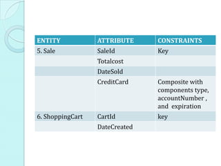
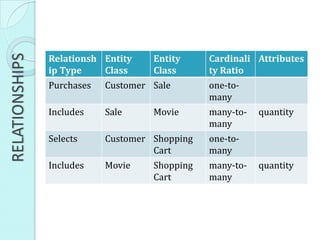
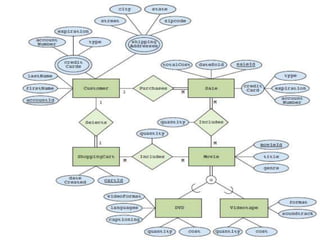
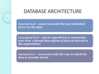
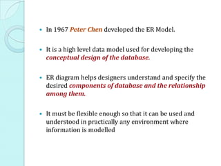
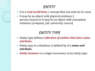
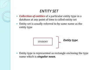
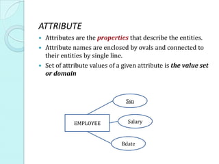
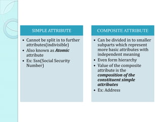
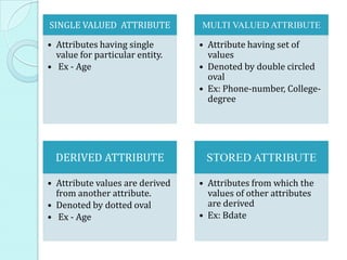
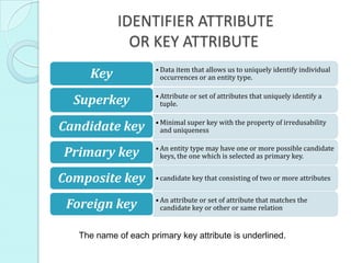
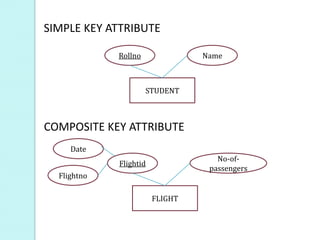
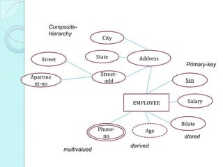
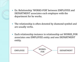
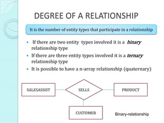
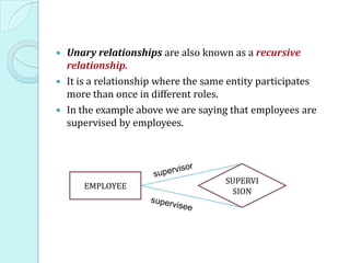
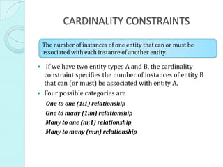
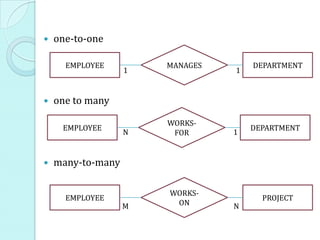
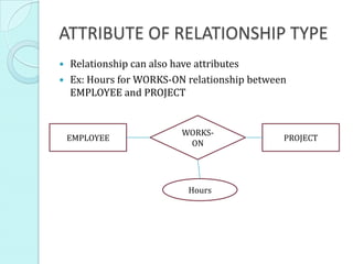
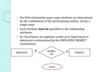
The document discusses entity relationship diagrams and database design. It defines key concepts such as entities, attributes, relationships and cardinalities. Entities can have single-valued or multi-valued attributes. Relationships connect entities and can be one-to-one, one-to-many, many-to-one, or many-to-many. Primary keys uniquely identify entities and foreign keys define relationships between entities. Together these elements form a conceptual model of entities and their relationships within a database.
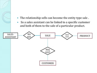
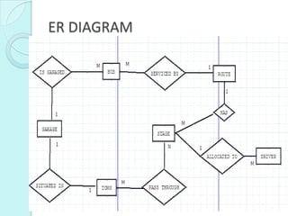
Data modeling is a process used to define and analyze data requirements needed to support the business processes within the scope of corresponding information systems in organizations.
● Data Modeling and Data Models.
● Business Rules (Translating Business Rules into Data Model Components).
● Emerging Data Models: Big Data and NoSQL.
● Degrees of Data Abstraction (External, Conceptual, Internal and Physical model).
This Home Delivery Restaurants for working and old age people. Easily to get the food and save the valuable time. Customer has been choose the best and elected food items.
Fundamentals of database system - Data Modeling Using the Entity-Relationshi...Mustafa Kamel Mohammadi
In this chapter you will learn
Relational data model concepts
What is entity?
What is attribute and it’s types
What is relationship?
What is an Entity-Relationship data model?
Relational data model constraints
Characteristics of relation
An Introduction,
Entities & Relationships,
Building an Entity-Relationship model,
Attributes and Identifiers,
Cardinality, Degree, Existence of
Relationships
Securing your Kubernetes cluster_ a step-by-step guide to success !KatiaHIMEUR1
Today, after several years of existence, an extremely active community and an ultra-dynamic ecosystem, Kubernetes has established itself as the de facto standard in container orchestration. Thanks to a wide range of managed services, it has never been so easy to set up a ready-to-use Kubernetes cluster.
However, this ease of use means that the subject of security in Kubernetes is often left for later, or even neglected. This exposes companies to significant risks.
In this talk, I'll show you step-by-step how to secure your Kubernetes cluster for greater peace of mind and reliability.
UiPath Test Automation using UiPath Test Suite series, part 3DianaGray10
Welcome to UiPath Test Automation using UiPath Test Suite series part 3. In this session, we will cover desktop automation along with UI automation.
Topics covered:
UI automation Introduction,
UI automation Sample
Desktop automation flow
Pradeep Chinnala, Senior Consultant Automation Developer @WonderBotz and UiPath MVP
Deepak Rai, Automation Practice Lead, Boundaryless Group and UiPath MVP
Key Trends Shaping the Future of Infrastructure.pdfCheryl Hung
Keynote at DIGIT West Expo, Glasgow on 29 May 2024.
Cheryl Hung, ochery.com
Sr Director, Infrastructure Ecosystem, Arm.
The key trends across hardware, cloud and open-source; exploring how these areas are likely to mature and develop over the short and long-term, and then considering how organisations can position themselves to adapt and thrive.
Epistemic Interaction - tuning interfaces to provide information for AI supportAlan Dix
Paper presented at SYNERGY workshop at AVI 2024, Genoa, Italy. 3rd June 2024
https://alandix.com/academic/papers/synergy2024-epistemic/
As machine learning integrates deeper into human-computer interactions, the concept of epistemic interaction emerges, aiming to refine these interactions to enhance system adaptability. This approach encourages minor, intentional adjustments in user behaviour to enrich the data available for system learning. This paper introduces epistemic interaction within the context of human-system communication, illustrating how deliberate interaction design can improve system understanding and adaptation. Through concrete examples, we demonstrate the potential of epistemic interaction to significantly advance human-computer interaction by leveraging intuitive human communication strategies to inform system design and functionality, offering a novel pathway for enriching user-system engagements.
GraphRAG is All You need? LLM & Knowledge GraphGuy Korland
Guy Korland, CEO and Co-founder of FalkorDB, will review two articles on the integration of language models with knowledge graphs.
1. Unifying Large Language Models and Knowledge Graphs: A Roadmap.
https://arxiv.org/abs/2306.08302
2. Microsoft Research's GraphRAG paper and a review paper on various uses of knowledge graphs:
https://www.microsoft.com/en-us/research/blog/graphrag-unlocking-llm-discovery-on-narrative-private-data/
Connector Corner: Automate dynamic content and events by pushing a buttonDianaGray10
Here is something new! In our next Connector Corner webinar, we will demonstrate how you can use a single workflow to:
Create a campaign using Mailchimp with merge tags/fields
Send an interactive Slack channel message (using buttons)
Have the message received by managers and peers along with a test email for review
But there’s more:
In a second workflow supporting the same use case, you’ll see:
Your campaign sent to target colleagues for approval
If the “Approve” button is clicked, a Jira/Zendesk ticket is created for the marketing design team
But—if the “Reject” button is pushed, colleagues will be alerted via Slack message
Join us to learn more about this new, human-in-the-loop capability, brought to you by Integration Service connectors.
And...
Speakers:
Akshay Agnihotri, Product Manager
Charlie Greenberg, Host
Elevating Tactical DDD Patterns Through Object CalisthenicsDorra BARTAGUIZ
After immersing yourself in the blue book and its red counterpart, attending DDD-focused conferences, and applying tactical patterns, you're left with a crucial question: How do I ensure my design is effective? Tactical patterns within Domain-Driven Design (DDD) serve as guiding principles for creating clear and manageable domain models. However, achieving success with these patterns requires additional guidance. Interestingly, we've observed that a set of constraints initially designed for training purposes remarkably aligns with effective pattern implementation, offering a more ‘mechanical’ approach. Let's explore together how Object Calisthenics can elevate the design of your tactical DDD patterns, offering concrete help for those venturing into DDD for the first time!
JMeter webinar - integration with InfluxDB and GrafanaRTTS
Watch this recorded webinar about real-time monitoring of application performance. See how to integrate Apache JMeter, the open-source leader in performance testing, with InfluxDB, the open-source time-series database, and Grafana, the open-source analytics and visualization application.
In this webinar, we will review the benefits of leveraging InfluxDB and Grafana when executing load tests and demonstrate how these tools are used to visualize performance metrics.
Length: 30 minutes
Session Overview
-------------------------------------------
During this webinar, we will cover the following topics while demonstrating the integrations of JMeter, InfluxDB and Grafana:
- What out-of-the-box solutions are available for real-time monitoring JMeter tests?
- What are the benefits of integrating InfluxDB and Grafana into the load testing stack?
- Which features are provided by Grafana?
- Demonstration of InfluxDB and Grafana using a practice web application
To view the webinar recording, go to:
https://www.rttsweb.com/jmeter-integration-webinar
Accelerate your Kubernetes clusters with Varnish CachingThijs Feryn
A presentation about the usage and availability of Varnish on Kubernetes. This talk explores the capabilities of Varnish caching and shows how to use the Varnish Helm chart to deploy it to Kubernetes.
This presentation was delivered at K8SUG Singapore. See https://feryn.eu/presentations/accelerate-your-kubernetes-clusters-with-varnish-caching-k8sug-singapore-28-2024 for more details.
DevOps and Testing slides at DASA ConnectKari Kakkonen
My and Rik Marselis slides at 30.5.2024 DASA Connect conference. We discuss about what is testing, then what is agile testing and finally what is Testing in DevOps. Finally we had lovely workshop with the participants trying to find out different ways to think about quality and testing in different parts of the DevOps infinity loop.
UiPath Test Automation using UiPath Test Suite series, part 4DianaGray10
Welcome to UiPath Test Automation using UiPath Test Suite series part 4. In this session, we will cover Test Manager overview along with SAP heatmap.
The UiPath Test Manager overview with SAP heatmap webinar offers a concise yet comprehensive exploration of the role of a Test Manager within SAP environments, coupled with the utilization of heatmaps for effective testing strategies.
Participants will gain insights into the responsibilities, challenges, and best practices associated with test management in SAP projects. Additionally, the webinar delves into the significance of heatmaps as a visual aid for identifying testing priorities, areas of risk, and resource allocation within SAP landscapes. Through this session, attendees can expect to enhance their understanding of test management principles while learning practical approaches to optimize testing processes in SAP environments using heatmap visualization techniques
What will you get from this session?
1. Insights into SAP testing best practices
2. Heatmap utilization for testing
3. Optimization of testing processes
4. Demo
Topics covered:
Execution from the test manager
Orchestrator execution result
Defect reporting
SAP heatmap example with demo
Speaker:
Deepak Rai, Automation Practice Lead, Boundaryless Group and UiPath MVP
Essentials of Automations: Optimizing FME Workflows with ParametersSafe Software
Are you looking to streamline your workflows and boost your projects’ efficiency? Do you find yourself searching for ways to add flexibility and control over your FME workflows? If so, you’re in the right place.
Join us for an insightful dive into the world of FME parameters, a critical element in optimizing workflow efficiency. This webinar marks the beginning of our three-part “Essentials of Automation” series. This first webinar is designed to equip you with the knowledge and skills to utilize parameters effectively: enhancing the flexibility, maintainability, and user control of your FME projects.
Here’s what you’ll gain:
- Essentials of FME Parameters: Understand the pivotal role of parameters, including Reader/Writer, Transformer, User, and FME Flow categories. Discover how they are the key to unlocking automation and optimization within your workflows.
- Practical Applications in FME Form: Delve into key user parameter types including choice, connections, and file URLs. Allow users to control how a workflow runs, making your workflows more reusable. Learn to import values and deliver the best user experience for your workflows while enhancing accuracy.
- Optimization Strategies in FME Flow: Explore the creation and strategic deployment of parameters in FME Flow, including the use of deployment and geometry parameters, to maximize workflow efficiency.
- Pro Tips for Success: Gain insights on parameterizing connections and leveraging new features like Conditional Visibility for clarity and simplicity.
We’ll wrap up with a glimpse into future webinars, followed by a Q&A session to address your specific questions surrounding this topic.
Don’t miss this opportunity to elevate your FME expertise and drive your projects to new heights of efficiency.
2. DATABASE ARCHITECTURE
External level – concerned with the way individual
users see the data
Conceptual level – can be regarded as a community
user view a formal description of data of interest to
the organization
Internal level – concerned with the way in which the
data is actually stored
3. In 1967 Peter Chen developed the ER Model.
It is a high level data model used for developing the
conceptual design of the database.
ER diagram helps designers understand and specify the
desired components of database and the relationship
among them.
It must be flexible enough so that it can be used and
understood in practically any environment where
information is modelled
4. ENTITY
It is a real world item / concept that can exist on it’s own.
It may be an object with physical existence (
person, house) or it may be an object with conceptual
existence (company ,job, university course)
ENTITY TYPE
Entity type defines collection of entities that have same
attribute.
Entity type in a database is defined by it’s name and
attribute.
Entity instance is a single occurrence of an entity type.
5. ENTITY SET
Collection of entities of a particular entity type in a
database at any point of time is called entity set
Entity set is usually referred to by same name as the
entity type
STUDENT
Entity type
Entity type is represented as rectangle enclosing the type
name which is singular noun.
6. ATTRIBUTE
Attributes are the properties that describe the entities.
Attribute names are enclosed by ovals and connected to
their entities by single line.
Set of attribute values of a given attribute is the value set
or domain
Ssn
EMPLOYEE Salary
Bdate
7. SIMPLE ATTRIBUTE COMPOSITE ATTRIBUTE
• Cannot be split in to further • Can be divided in to smaller
attributes(indivisible) subparts which represent
• Also known as Atomic more basic attributes with
attribute independent meaning
• Ex: Ssn(Social Security • Even form hierarchy
Number) • Value of the composite
attribute is the
composition of the
constituent simple
attributes
• Ex: Address
8. SINGLE VALUED ATTRIBUTE MULTI VALUED ATTRIBUTE
• Attributes having single • Attribute having set of
value for particular entity. values
• Ex - Age • Denoted by double circled
oval
• Ex: Phone-number, College-
degree
DERIVED ATTRIBUTE STORED ATTRIBUTE
• Attribute values are derived • Attributes from which the
from another attribute. values of other attributes
• Denoted by dotted oval are derived
• Ex - Age • Ex: Bdate
9. IDENTIFIER ATTRIBUTE
OR KEY ATTRIBUTE
Key • Data item that allows us to uniquely identify individual
occurrences or an entity type.
Superkey • Attribute or set of attributes that uniquely identify a
tuple.
Candidate key • Minimal super key with the property of irredusability
and uniqueness
Primary key • An entity type may have one or more possible candidate
keys, the one which is selected as primary key.
Composite key • candidate key that consisting of two or more attributes
Foreign key • An attribute or set of attribute that matches the
candidate key or other or same relation
The name of each primary key attribute is underlined.
10. SIMPLE KEY ATTRIBUTE
Rollno Name
STUDENT
COMPOSITE KEY ATTRIBUTE
Date
No-of-
Flightid
passengers
Flightno
FLIGHT
11. CRITERIA FOR SELECTING IDENTIFIERS
Some entities have more than one candidate identifier, so the
following criteria should be used:
Choose identifier that will not change in value over the life of
each instance of the entity type
Choose identifier that is guaranteed to have valid values and
will not be null (or unknown). If composite, make sure all
parts will have valid values
12. Avoid the use of intelligent identifiers whose structure
indicates classifications, locations or people that might
change. e.g. the first two digits of an identifier may
indicate a warehouse location, but such codes are often
changed as conditions change, which renders them
invalid.
13. Composite-
hierarchy
City
Street State Address
Primary-key
Street-
Apartme
add Ssn
nt-no
EMPLOYEE Salary
Bdate
Phone- Age
no stored
derived
multivalued
14. COMPLEX ATTRIBUTE
Composite and mutivalued attribute can also be nested
arbitrarily to form complex key.
Areacode
Phoneno
Street
Phone
Apartment
Street-add
no
Address-
Phone State
Address
City
Zip
15. SHOULD ‘ADDRESS’ ATTRIBUTE BE REPRESENTED
AS SIMPLE ATTRIBUTE OR COMPOSITE?
Composite attributes are useful to model situations in which
user refers to the composite attribute as a unit but other
times refer specifically to it’s components.
If the composite attribute is to be referenced only as a
whole then there is no need to represent it in to component
attributes.
Ex: if there is no need to refer to the individual components
of an address ( ZIP, code, street etc) then the whole address
can be designated as a simple attribute.
16. RELATIONSHIP TYPE
When attribute of an entity refers to another entity type
there exists relationship
Ex: attribute ‘Manager’ of DEPARTMENT refers to another
employee who manages the department.
Attribute ‘Controlling-dep’t refers to another department
that controls the project.
In ER diagram these references must be represented as
relationship and not attributes.
17. Ex: Relationship ‘WORKS-FOR’ between EMPLOYEE and
DEPARTMENT associates each employee with the
department for he works.
The relationship is often denoted by diamond symbol and
are usually verbs.
Each relationship instance in relationship set WORKS_FOR
associates one EMPLOYEE entity and one DEPARTMENT
entity.
WORKS-
EMPLOYEE DEPARTMENT
FOR
18. DEGREE OF A RELATIONSHIP
It is the number of entity types that participate in a relationship
If there are two entity types involved it is a binary
relationship type
If there are three entity types involved it is a ternary
relationship type
It is possible to have a n-array relationship (quaternary)
SALESASSIST SELLS PRODUCT
CUSTOMER Binary-relationship
19. Unary relationships are also known as a recursive
relationship.
It is a relationship where the same entity participates
more than once in different roles.
In the example above we are saying that employees are
supervised by employees.
SUPERVI
EMPLOYEE
SION
20. CARDINALITY CONSTRAINTS
The number of instances of one entity that can or must be
associated with each instance of another entity.
If we have two entity types A and B, the cardinality
constraint specifies the number of instances of entity B
that can (or must) be associated with entity A.
Four possible categories are
One to one (1:1) relationship
One to many (1:m) relationship
Many to one (m:1) relationship
Many to many (m:n) relationship
21. one-to-one
EMPLOYEE MANAGES DEPARTMENT
1 1 1
one to many
WORKS-
EMPLOYEE DEPARTMENT
N FOR 1
many-to-many
WORKS-
EMPLOYEE PROJECT
M ON N
22. ROLE NAME
Some entities participate more than once in a relationship
type in different roles.
Role name represents role that a participating entity from the entity
type plays in the relationship.
Ex: Employee plays the role of supervisor as well as
supervisee.
If the participating entity types are distinct then there is
no need for role name else role name is a must.
23. PARITICIPATION
CONSTRAINTS(OPTIONALITY)
Specifies if existence of an entity depends on it being related to
another entity via relationship.
Specifies minimum number of relationship instances
each entity can participate in .
This is called minimum cardinality constraint.
Two type of the participation are : Total And Partial
TOTAL
PARTICIPATION
PARTIAL
24. Ex: if company policy says that every employee must work for
the department then participation of employee in work-for is
total.
WORKS-
EMPLOYEE DEPARTMENT
FOR 1
N
Total participation is also called existence dependencies.
Every entity in total set of employee must be related to a
department via WORKS-FOR
But we can’t say that every employee must MANAGE a
department .
Hence relationship is partial.
Total participation is indicated by double line and partial
participation by single line.
Cardinality + Optionality = multiplicity
25. ATTRIBUTE OF RELATIONSHIP TYPE
Relationship can also have attributes
Ex: Hours for WORKS-ON relationship between
EMPLOYEE and PROJECT
WORKS-
EMPLOYEE PROJECT
ON
Hours
26. Attributes of 1:1 or 1:N relationship can be migrated to
one of the participating entity types.
Ex: Start-date attributes of MANAGES can be attribute of
either DEPARTMENT or EMPLOYEE though conceptually
it belongs to manages.
1 1
EMPLOYEE MANAGES DEPARTMENT
Start-date
27. Because each EMPLOYEE MANAGES is a 1:1 relationship.
So every DEPARTMENT /EMPLOYEE entity participate in
atmost one relationship instance.
So value of the Start-date can be determined separately
either by participating DEPARTMENT entity or
participating EMPLOYEE entity.
28. For 1:N relationship a relationship attribute can be
migrated only to entity type on N-side of relationship
Start-date attribute here can added only to employee.
N WORKS- 1
EMPLOYEE DEPARTMENT
FOR
Start-date
29. For M:N relationship types some attribute are determined
by the combination of the participating entities, not by a
single enity.
Such attribute must be specified as the relationship
attributes
Ex: No.of hours an employee works on is department is
determent is determined by the EMPLOYEE-PROJECT
combination.
M WORKS- N
EMPLOYEE PROJECT
ON
Hours
30. WEAK ENTITY AND STRONG ENTITY
Entity type that doesn’t have a key attribute on it’s own is
called weak entity and the Regular entity types that have key
value is called strong entities.
Entity belonging to weak entity type is identified by being
related to specific entities from another entity type in
combination with one of their attribute value.
We call this entity type as identifying or owner entity
type (Parent/Dominanat Entity type)
The relationship that connects owner entity type to weak
entity is called Identifying relationship.
The weak entities are also called as child entity type or
subordinate entity type
31. Weak entities have always a total participating constraint
because they cannot be identified without an owner entity.
Relationship
1 N
EMPLOYEE HAS DEPENDENTS
Dependent-
name
Employee
32. But converse is not true.
Every existence dependency does not has result is weak
entities.
Ex: Driver license entity can’t exist without person entity
though it has it’s own key (license number)
There is total participation but not weak entity
Weak entity type normally has partial
key(descriminator)
Partial key are set of attributes that can uniquely identify weak
entities that are related to some owner entity
33. Partial key attribute is denoted with underlined or dotted line.
Weak entities can sometimes be represented as complex
attributes (composite and multivalued attributes)
Choice of the representation is done by DB designer.
If there are many attributes then we can better represent
them as weak entity.
Also if it participates independently in any other
relationship type other than it’s own identifying
relationship then it should not be modeled as complex
attributes.
34. DESIGN CHOICE FOR ER CONCEPTUAL
MODEL
It is very difficult to determine if a particular concept
must be represented as entity type or attribute or
relationship type
Some important concepts to be remembered are:
A) Concept may be first modeled as an attribute and then
refined in to a relationship because it is determined that an
attribute is reference to another attribute . A pair of such
attribute that are inverses of one another are refined to as
binary relationship
35. EMPLOYEE Department
DEPARTMENT Employees
Can be refined to binary relation
N WORKS- 1
EMPLOYEE DEPARTMENT
FOR
36. B) An attribute that exists in several entity types may be
elevated or promoted to an independent entity.
Ex: Suppose several entity types in an UNIVERSITY
DATABASE such as student , instructor & course each has
an attribute named department . Then we can better keep
an entity named department with a single attribute
department name and relate it to 3 entity types student ,
instructor & course via appropriate relationship.
37. INSTRUCTOR Dept-name
STUDENT Dept-name
COURSE Dept-name
Can be refined as
DEPARTMENT
WORKS REGISTE BELONG
RED S-TO
-FOR
INSTRUCTOR STUDENT COURSE
38. Inverse refinement to previous case:
If an entity type department exists in initial design
with a single attribute dept-name and is related to
only one other entity type student , in this case
department may be reduced as an attribute of the
student
39. ALTERNATE NOTATIONS
We can also associate pair of integer (min,max) with each
participation of entity type in a relationship type. These
are termed structural constraints
0<=min<=max and max>=1
Min>0 implies total particiaption
Min=0 implies partial participation
40. CHOOSING BETWEEN BINARY AND
TERNARY RELATIONSHIP
Consider the ER diagram
Qty
SUPPLIER SUPPLY PROJECT
Sname
Pname
PART
Partno
41. We can refine it to three binary relations
Sname Pname
Qty
SUPPLI
SUPPLIER ES PROJECT
CAN USES
SUPPLY
PART
Partno
42. CAN_SUPPLY relationship between SUPPLIER and PART
include instances (s,p) whenever SUPPLIER s can supply
PART p(to any project).
USES relationship between PROJECT and PART include
instances (j,p) whenever PROJECT j uses PART p.
SUPPLIES relationship between SUPPLIER and PROJECT
include instances (s,j) whenever SUPPLIER s SUPPLIES
some PART to PROJECT j.
The existence of relationship instances (s,p) , (j,p) , (s,j)
does not necessarily imply that the instance (s,j,p) exists
in ternary relationship supply because meaning is
different.
43. Solution is to include the ternary relationship plus one or
more of the binary relationship if they represent different
meaning and all are needed by the application.
So ternary relationship supply can be represented as the
weak entity type with three identifying relationship
44. Qty
Sname Pname
N N 1
1
SUPPLIER SS SUPPLY SPJ PROJECT
N
SP
1
PART
Partno
45. DEALING WITH TERNARY RELATIONSHIPS
Consider the below relationship. ]It is no longer clear which
sales assistant sold a customer a particular product.
So try replacing the ternary relations hip with an entity type and
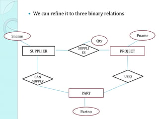
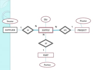
a set of binary relationships.
SALES-
SELLS PRODUCT
ASSISTANT
SELLS SELLS
CUSTOMER
46. The relationship sells can become the entity type sale .
So a sales assistant can be linked to a specific customer
and both of them to the sale of a particular product.
SALES- MA INVO
SALE PRODUCT
ASSISSTANT KES LVES
REQ
UEST
CUSTOMER
47. REMOVING REDUNDANT RELATIONSHIP
Entities can be related indirectly by two relationships.
A relationship is redundant if it can be completely
represented by alternate transitive relationships
48.
49. CONFIRMING OPTIONALITY AND
CARDINALITY OF RELATIONSHIP
Use an `entity set diagram' to show entity examples graphically
Consider the example of `course is_studied_by student'.
50. Use the diagram to show all possible relationship
scenarios.
Go back to the requirements specification and check to
see if they are allowed.
If not, then put a cross through the forbidden
relationships
This allows you to show the cardinality and optionality of
the relationship
51.
52. DERIVING THE RELATIONSHIP PARAMETERS
To check we have the correct parameters (sometimes also
known as the degree) of a relationship, ask two questions:
1. One course is studied by how many students?
Answer = `zero or more'.
This gives us the degree at the `student' end.
The answer `zero or more' needs to be split into two parts.
The `more' part means that the cardinality is `many'.
The `zero' part means that the relationship is `optional'.
If the answer was `one or more', then the relationship
would be `mandatory'.
53. 2.One student studies how many courses?
Answer = `One'
This gives us the degree at the `course' end of the
relationship.
The answer `one' means that the cardinality of this
relationship is 1, and is `mandatory'
If the answer had been `zero or one', then the cardinality
of the relationship would have been 1, and be `optional'.
54. CONSTRUCTING AN ER MODEL
Before beginning to draw the ER model, read the
requirements specification carefully.
Document any assumptions you need to make.
1.Identify entities
• list all potential entity types. These are the
object of interest in the system. It is better to
put too many entities in at this stage and them
discard them later if necessary.
55. 2.Remove duplicate entities
• Ensure that they really separate entity types or just
two names for the same thing
• Also do not include the system as an entity type
• e.g. if modelling a library, the entity types might be
books, borrowers, etc.
• The library is the system, thus should not be an
entity type.
56. 3.List the attributes of each entity
• Ensure that the entity types are really needed.
• Are any of them just attributes of another entity
type?
• If so keep them as attributes a nd cross them
off the entity list.
• Do not have attributes of one entity as
attributes of another entity!
57. 4.Mark the primary keys
• Which attributes uniquely identify instances of
that entity type?
• This may not be possible for some weak
entities.
5.Define the relationships
• Examine each entity type to see its relationship
to the others.
58. 6.Describe the cardinality and optionality
of the relationships
• Examine the constraints betwee n participating
entities.
7.Remove redundant relationships
• Examine the ER model for redundant
relationships.
ER modelling is an iterative process, so draw several
versions, refining each one until you are happy with it.
Note that there is no one right answer to the problem, but
some solutions are better than others!
59. EXAMPLE
“A Country Bus Company owns a number of busses.
Each bus is allocated to a particular route, although some
routes may have several busses. Each route passes through
a number of towns. One or more drivers are allocated to
each stage of a route, which corresponds to a journey
through some or all of the towns on a route. Some of the
towns have a garage where busses are kept and each of the
busses are identified by the registration number and can
carry different numbers of passengers, since the vehicles
vary in size and can be single or double-decked. Each route
is identified by a route number and information is available
on the average number of passengers carried per day for
each route. Drivers have an employee number, name ,
address, and sometimes a telephone number.”
60. ENTITIES
Bus - Company owns busses and will hold information
about them.
Route - Buses travel on routes and will need described.
Town - Buses pass through towns and need to know about
them
Driver - Company employs drivers, personnel will hold
their data.
Stage - Routes are made up of stages
Garage - Garage houses buses, and need to know where
they are.
61. RELATIONSHIPS
A bus is allocated to a route and a route may have several
buses.
Bus-route (m:1) - is serviced by
A route comprises of one or more stages.
route-stage (1:m) comprises
One or more drivers are allocated to each stage.
driver-stage (m:1) is allocated
A stage passes through some or all of the towns on a
route.
stage-town (m:n) passes-through
62. A route passes through some or all of the towns
route-town (m:n) passes-through
Some of the towns have a garage
garage-town (1:1) is situated
A garage keeps buses and each bus has one `home' garage
garage-bus (m:1) is garaged
72. ENHANCED ER DIAGRAM
The EER diagram includes the concepts of
Subclass and super class
Specialization and Generalization
Categorization
Attribute and relationship inheritance.
73. SUBCLASS SUPERCLASS AND
INHERITANCE
In many cases entity types has numerous sub grouping of
it’s entities that are meaningful and need to be
represented explicitly because of their significance to
database application.
74. Here each of the sub groupings is called subclass of the
EMPLOYEE entity type.
EMPLOYEE entity type is called super class for each of
these subclasses
The relationship between super class and any one of it’s
subclass is called the super class/subclass or simply
class/subclass relationship.
Member entity of the subclass represents the same real world
entity as some member of superclass and the Subclass entity
has specific distinct role
75. An entity that is a member of subclass is also a member of
super class and can optionally be member of any number
of subclasses.
Important concept associated with subclass is type
inheritance.
Subclass entity possess it’s own attributes as well inherits
all the attributes possessed by it’s superclass.
The entity also inherits the relationships that superclass
participtes
76. SPECIALIZATION
Specialisation is a process of defining set of subclasses of an
entity type.
This entity type is called superclass of the specialisation.
Set of subclasses that form specialisation is defined based
on some distinguishing characters of entities in the
superclass.
Ex: Job type , method-of-pay
77. The subclass that defines a specialisation are attached by
line to circle to represent the specialisation,which is
connected to superclass.
The subset symbol on each line connecting a subclass to
the circle indicates direction of the superclass/subclass
relationship.
Attributes that apply only to entities of particular entity
types – specific/local attributes.
Subclass also participates in specific relationships.
78. WHY INCLUDE SPECIALISATION CONCEPT?
1. Certain attributes may apply only to
specific entity.
• A subclass is defined to group the entities
to which the attributes apply.
2. Some relationship types may be
participated in by only specific entities.
79. IN SPECIALISATION:
1.Define a set of subclass of entity type
2. Establish additional specific attributes with each
subclass
3.Establish additional specific relationship types
between each subclass and other entity types or
other subclass
80. GENERALISATION
The reverse process of abstraction in which we suppress the
differences among several entity types, identify their common
features and generalize them in to single super class of which
original entity types are special subclasses.
Vehicle-
Price Vehicle-id Price
id
No-of-
pass CAR Licens TRUCK License
e-no -no
Max- No-of-
speed axles Tonnage
81. Licens
e-no
Vehicle-
Price
id
VEHICLE
d
No-of-
pass CAR TRUCK
Max- No-of-axles Tonnage
speed
82. CONSTRAINTS ON SPECIALIZATION AND
GENERALIZATION
Predicate-defined Attribute defined- User-defined
subclasses specialization subclass
• Determine • Membership • no condition
exactly those condition for determines
entities that subclasses on membership
will become same attribute • Membership in
members of of the super a subclass is
each subclass class determined by
by a condition. • Attribute is the database
called the users by
defining applying an
attribute of the operation to
specialization add an entity to
• Example: the subclass
JobType
83. Hence, we have four types of specialization/generalization
based on the paticipation of superclass entities in sub classes:
Disjoint, total
Disjoint, partial
Overlapping, total
Overlapping, partial
Generalization usually is total because the superclass is derived
from the subclasses.
85. SPECIALIZATION / GENERALIZATION
HIERARCHIES, LATTICES
A subclass may itself have further subclasses specified on it
Forms a hierarchy or a lattice.
Hierarchy has a constraint that every subclass has only one
superclass (called single inheritance)
In a lattice, a subclass can be subclass of more than one
superclass (called multiple inheritance)
86. In a lattice or hierarchy, a subclass inherits attributes not
only of its direct superclass, but also of all its
predecessor superclasses
In specialization, start with an entity type and then define
subclasses of the entity type by successive specialization
(top down conceptual refinement process)
In generalization, start with many entity types and
generalize those that have common properties (bottom
up conceptual synthesis process).
A subclass with more than one superclass is called a
shared subclass
88. CATEGORIES (UNION TYPES)
Model a single super class /subclass relationship with more
than one super class
Super classes represent different entity types .
Example:
Database for vehicle registration, vehicle owner can be a
person, a bank (holding a lien on a vehicle) or a company.
◦ Category (subclass) OWNER is a subset of the union of
the three super classes COMPANY, BANK, and PERSON
◦ A category member must exist in at least one of its
super classes
This is difference from shared subclass, which is subset of the
intersection of its super classes (shared subclass member must
exist in all of its super classes).
89.
90. CASE IN POINT: E-R MODEL FOR
ONLINE SALES FOR BIGHIT VIDEO
“ BigHit Video Inc. wants to create an information system
for online sales of movies in both DVD and videotape format.
People will be allowed to register as customers of the online site
and to update their stored information. Informa-tion must be
maintained about customers ’ shipping addresses, e-mail ad-
dresses and credit cards. In a single sale, customers will be
allowed to purchase any quantity of videos. The items in a
single sale will be shipped to a single address and will have a
single credit card charge A customer will be provided with a
virtual shopping cart to store items to be purchased. As each
item is selected, it is added to the shopping cart. When the
customer finishes shopping, he will be directed to a checkout
area where he can purchase all of the items in the shopping
cart. At this time, payment and shipping information is entered.
Once the sale is complete, the shopping cart will be deleted and
the customer will be sent a receipt by e-mail.”
91. IDENTIFY ENTITY AND ATTRIBUTES ENTITY ATTRIBUTE CONSTRAINTS
1.Customer accountId Key
lastName Not null
firstName
shippingAddresses Multivalued
composite with
components name,
street, city,
state, zipcode
emailAddress
creditCards Multivalued
composite with
components type,
accountNumber ,
expiration
password Not null at least 6
characters
92. ENTITY ATTRIBUTE CONSTRAINTS
2. Movie Movieid Key
Title
Genre
Media Either “dvd” or
“videotape”
determines
subclass
3. DVD Languages Subclass of Movie
Videoformat
Captioning
4. Videotape Format Subclass of Movie
Soundtrack
93. ENTITY ATTRIBUTE CONSTRAINTS
5. Sale SaleId Key
Totalcost
DateSold
CreditCard Composite with
components type,
accountNumber ,
and expiration
6. ShoppingCart CartId key
DateCreated
94. Relationsh Entity Entity Cardinali Attributes
RELATIONSHIPS
ip Type Class Class ty Ratio
Purchases Customer Sale one-to-
many
Includes Sale Movie many-to- quantity
many
Selects Customer Shopping one-to-
Cart many
Includes Movie Shopping many-to- quantity
Cart many