Downloaded 862 times


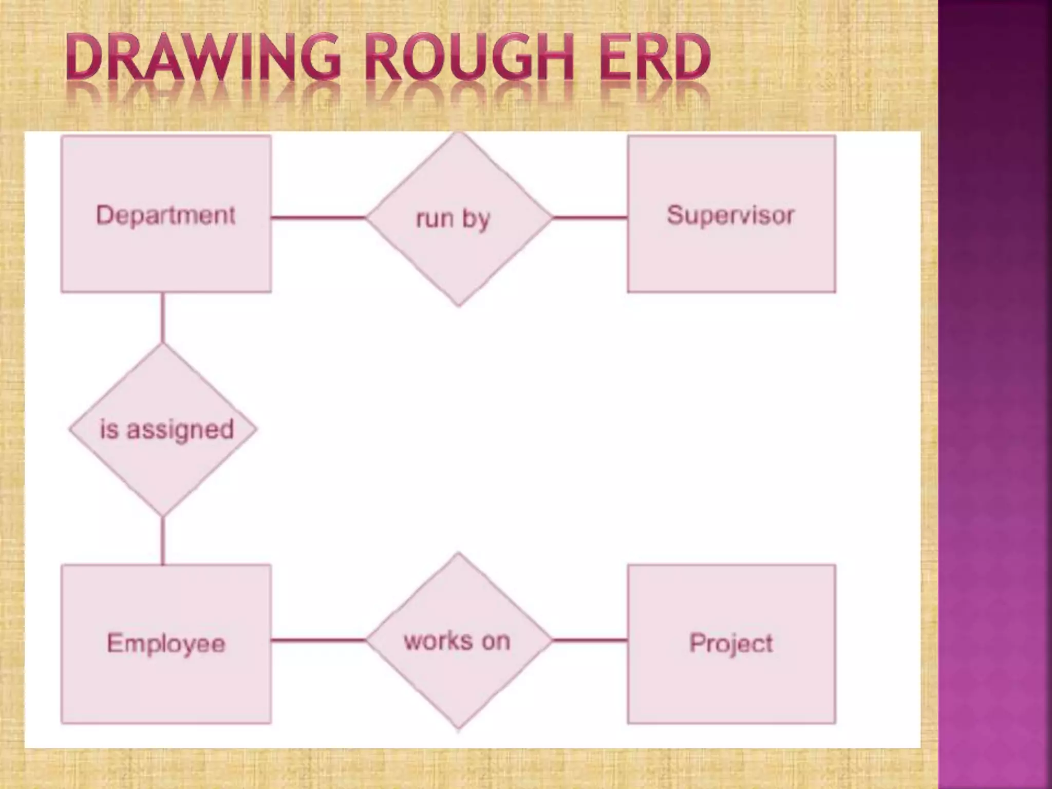


Entity Relationship Diagrams (ERDs) are used to model relationships between entities in a database. The document discusses ERD components like entities, relationships, cardinality, and attributes. It provides an example of an ERD for a company with departments, supervisors, employees, and projects. Key entities are identified and their relationships and attributes are represented in the example ERD diagrams.