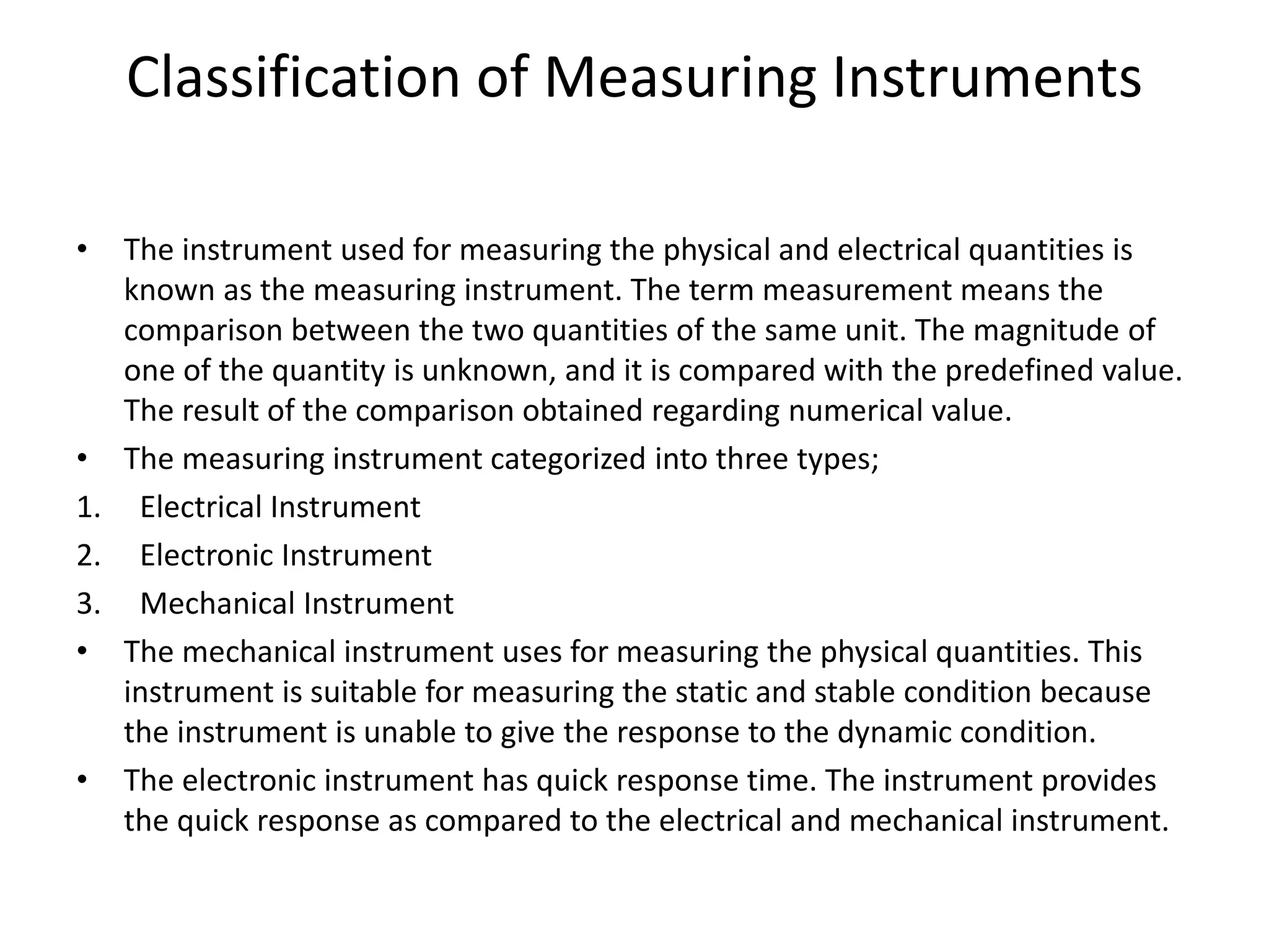
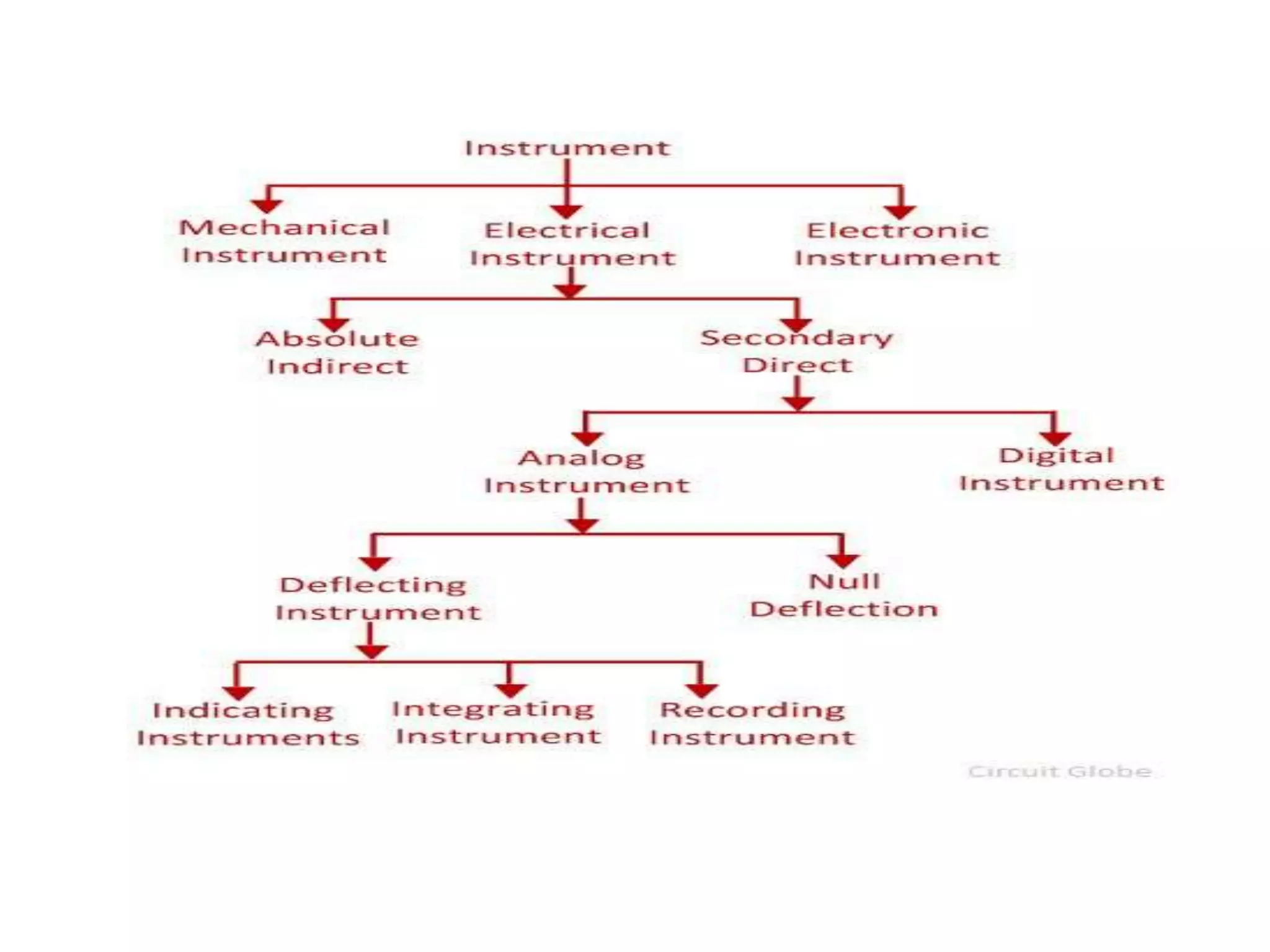
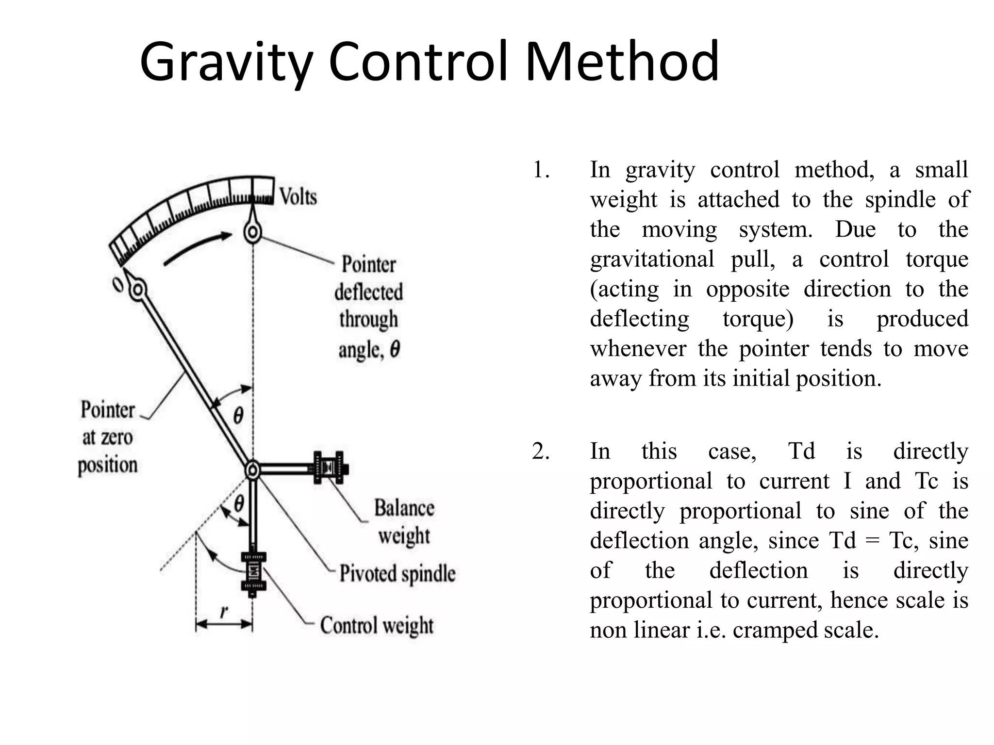
1. The document discusses different types of measuring instruments including electrical, electronic, and mechanical instruments.
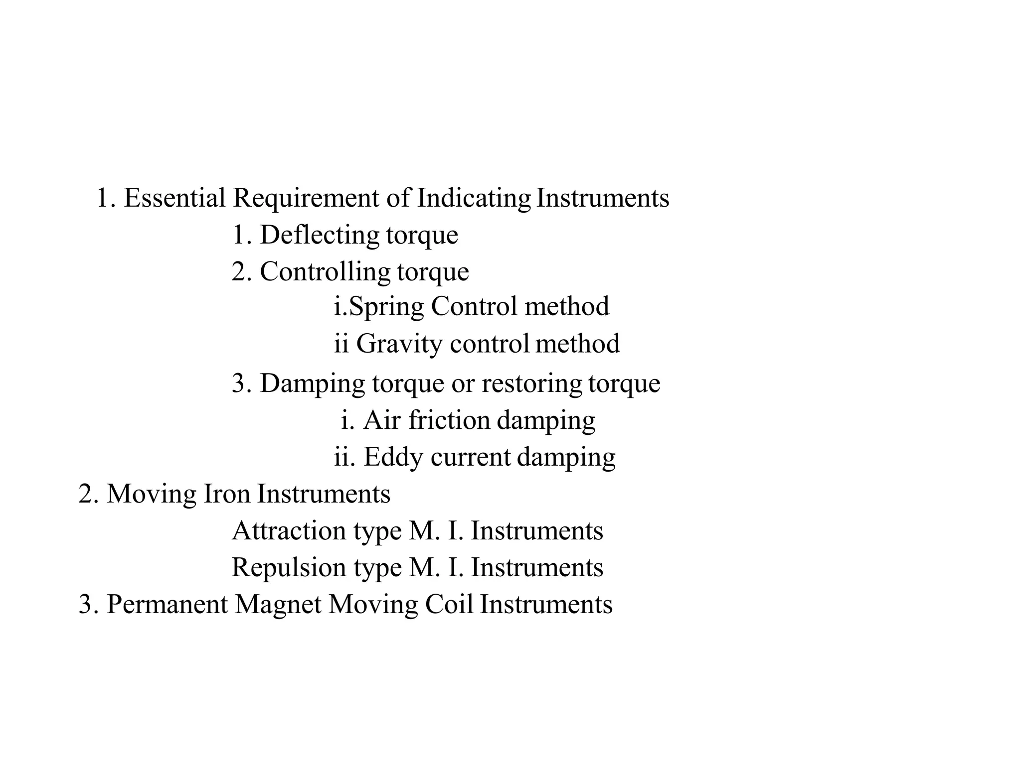
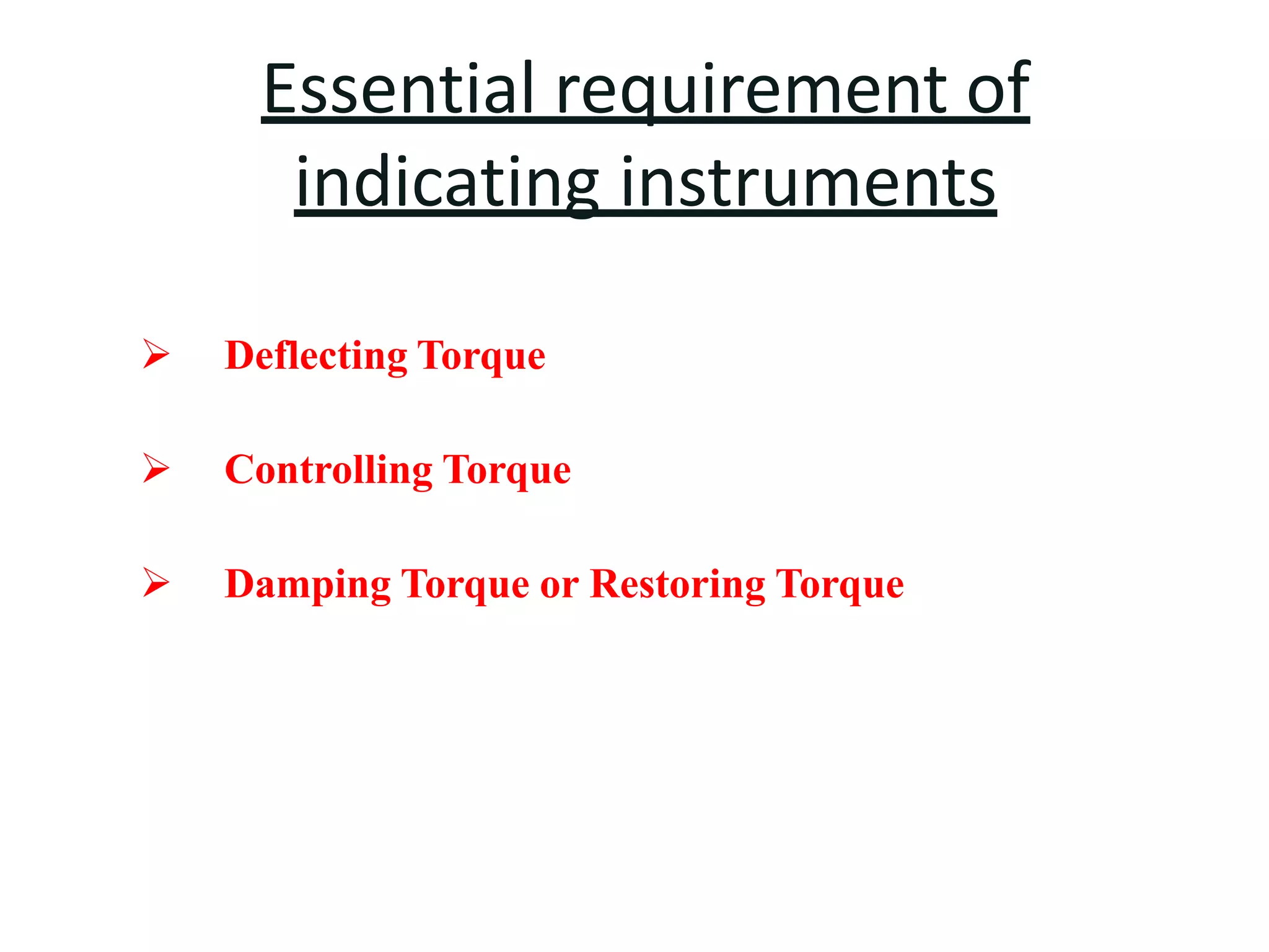
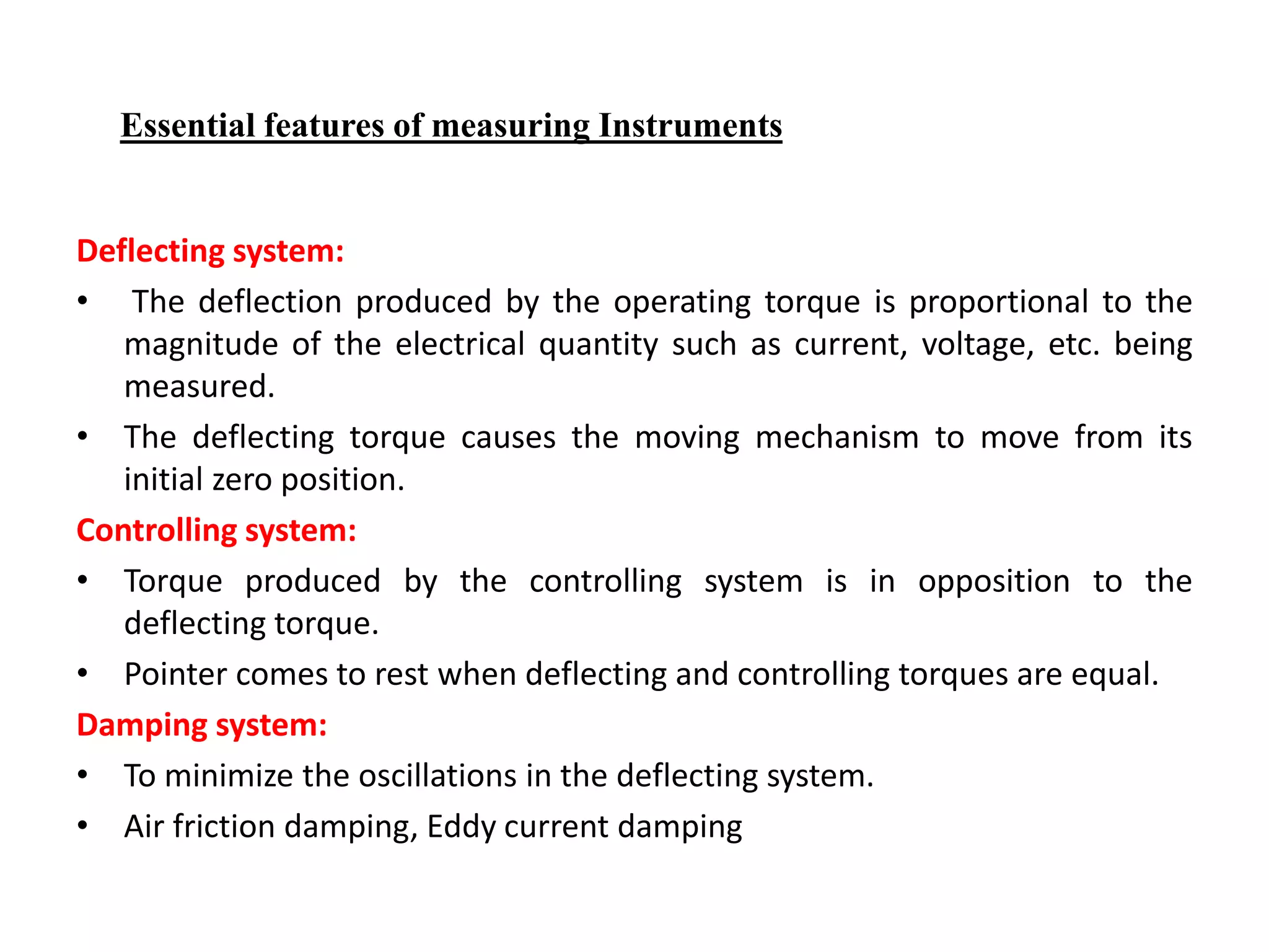
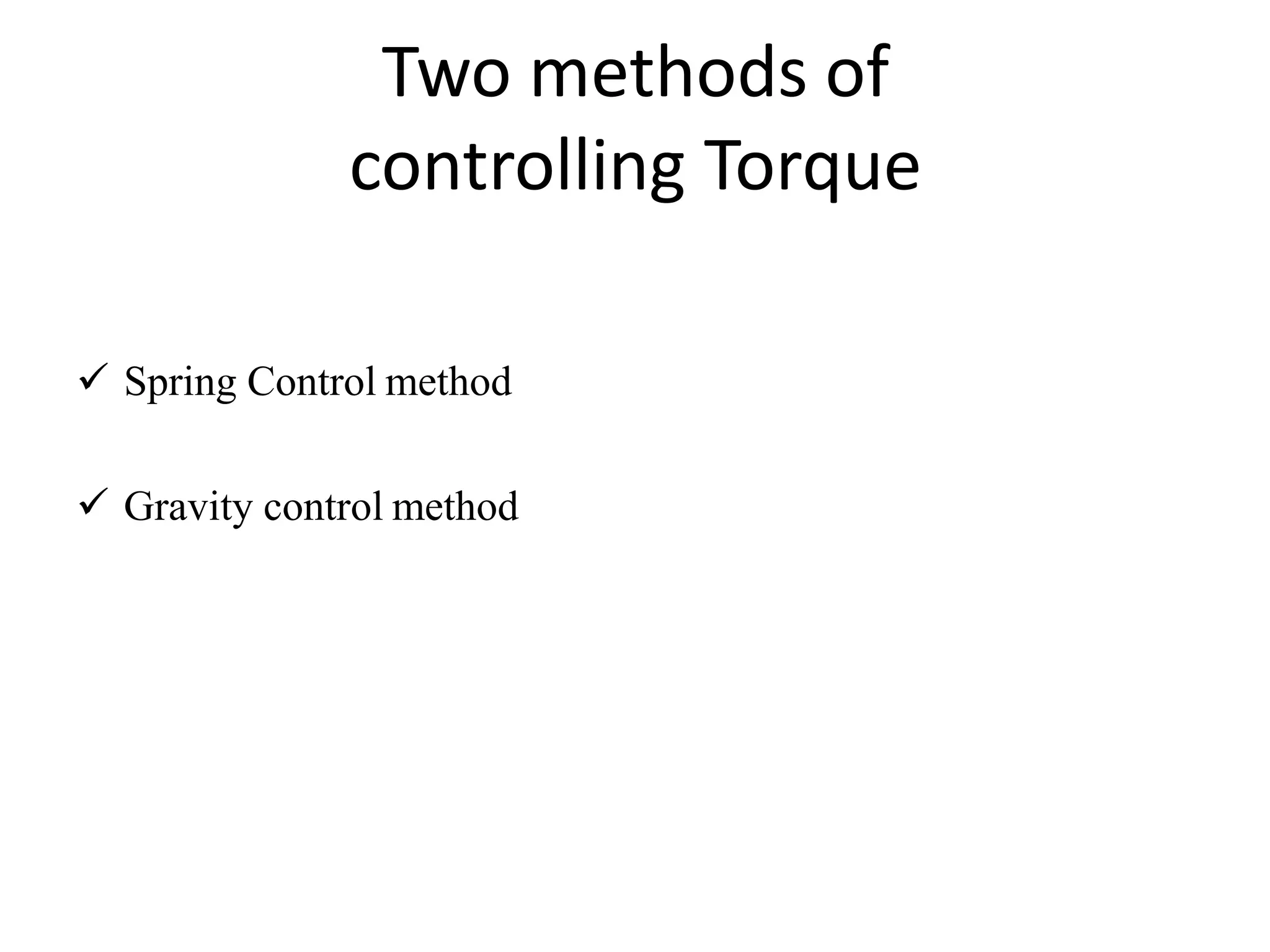
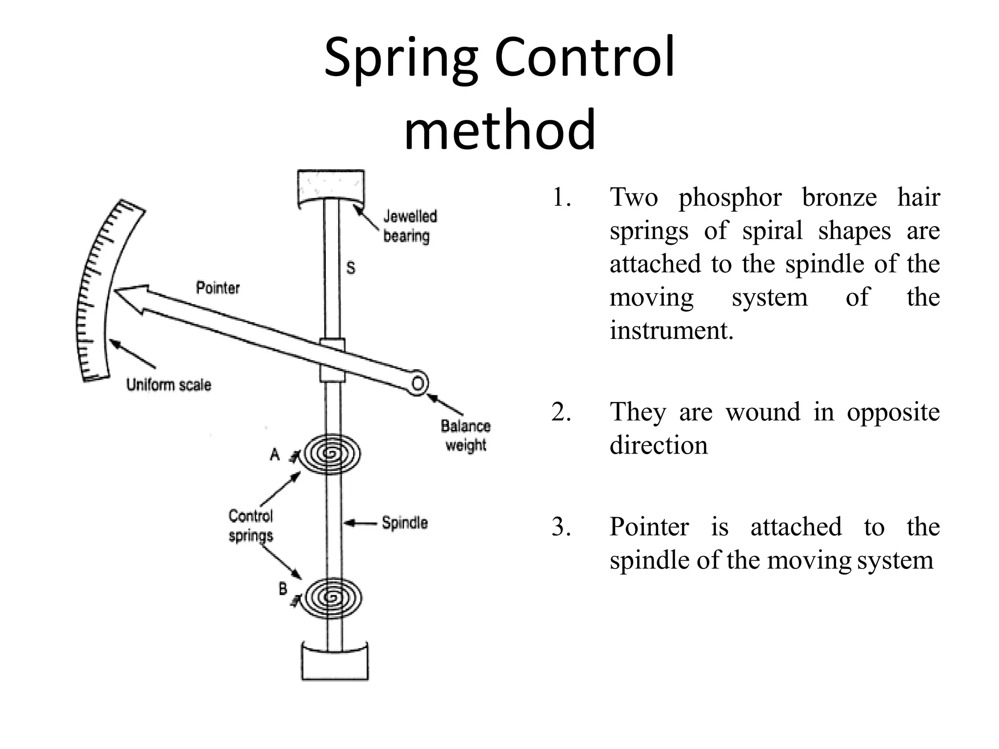
2. Measuring instruments are further classified based on their operating principles, including their deflecting, controlling, and damping systems.
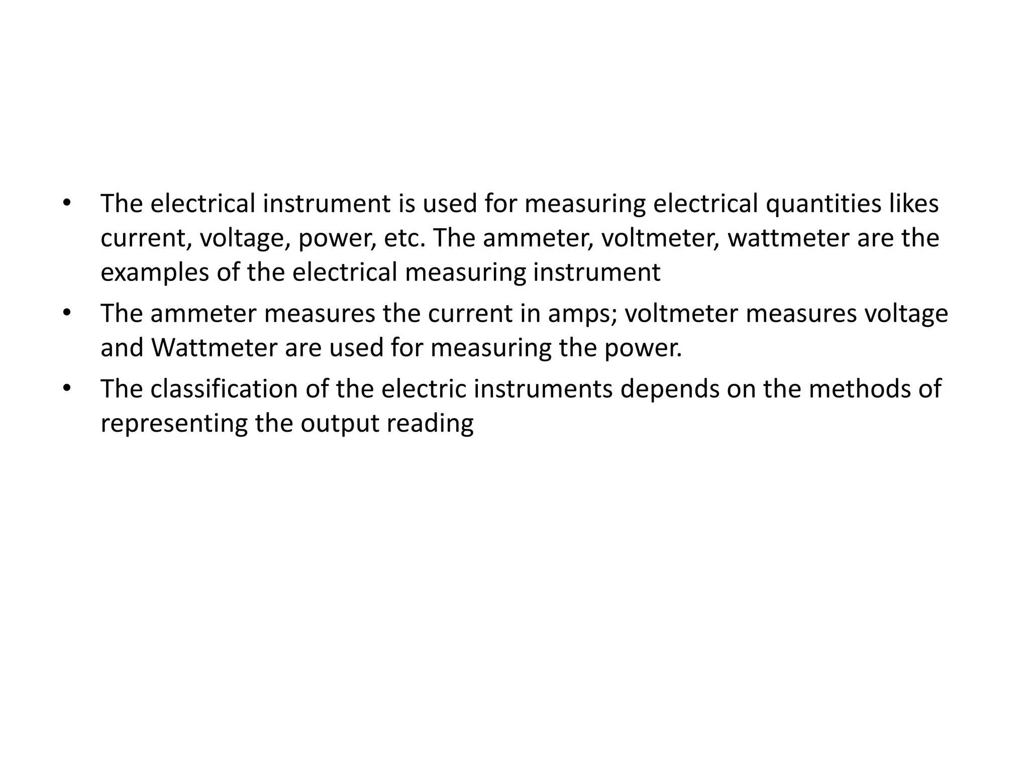
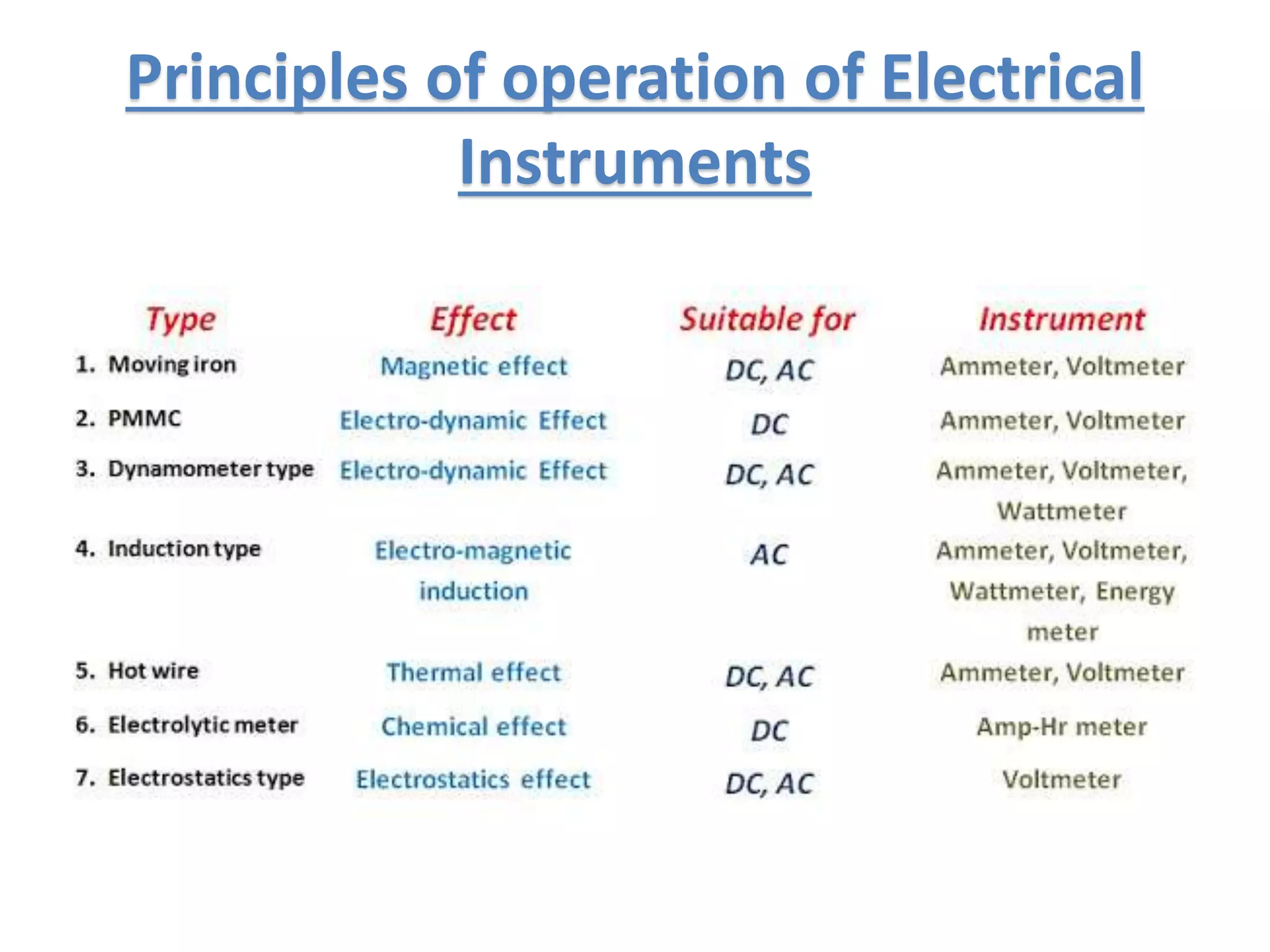
3. Common examples of electrical measuring instruments are ammeters, voltmeters, and wattmeters which measure current, voltage, and power respectively. These instruments work using principles like magnetic, electromagnetic induction, and thermal effects.


![ELECTRICAL MEASUREMENT & MEASURING INSTRUMENTS [Emmi- (NEE-302) -unit-1]](https://cdn.slidesharecdn.com/ss_thumbnails/emmi-nee-302-unit-1-170607090405-thumbnail.jpg?width=640&height=640&fit=bounds)