Download to read offline

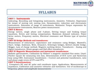
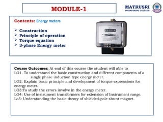


The document outlines the syllabus and course content for a subject on energy meters at Matrusri Engineering College, covering essential topics such as energy meter construction, measuring techniques, error analysis, and adjustments. Students will learn about the operational principles of single-phase induction type energy meters, various measurement instruments, and the impacts of errors due to components like magnets and temperature variations. The course aims to provide a comprehensive understanding of energy measurement and related instrumentation in electrical engineering.