This document provides information about various topics related to electricity and circuits, including:
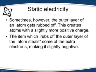
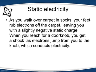
- Static electricity is caused by an imbalance of electric charges, usually through friction.
- Electric fields are regions surrounding charged objects that can exert force on other charges.
- Current is the flow of electric charge. It is measured in amperes and defined as the rate of flow of electric charge past a point.
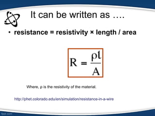
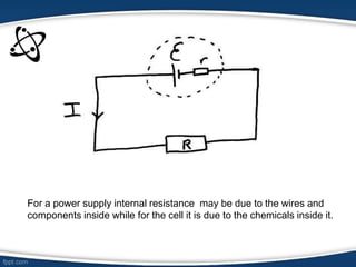
- Resistance opposes the flow of current and is measured in ohms. It depends on the material and its temperature.
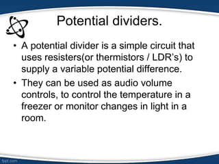
- Kirchhoff's laws and combinations of resistances describe how current and voltage are related in circuits.