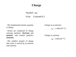
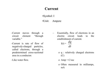
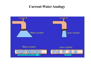
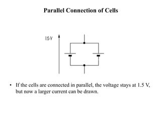
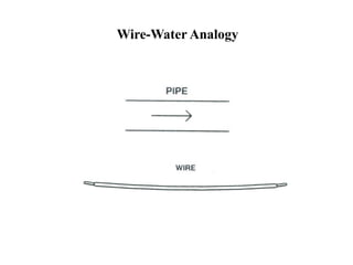
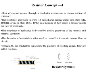
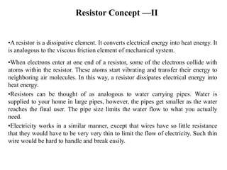
This document provides an introduction to key concepts related to electricity including charge, current, voltage, circuits, and circuit elements. It defines charge as the fundamental electric quantity carried by electrons and protons. Current is defined as the rate of flow of electrons through a conductor. Voltage is the potential difference required to move charge between two points. Analogies are provided between electric circuits and water flow. Key circuit elements like resistors and capacitors are introduced along with their symbols, units of measurement, and functions. Formulas for resistance, capacitance, and their characteristics are also outlined.
based on class 10 chapter electricity.
consists of topic such as-
electric potential,electric current, resistors ,series and parallel connection, heating effect of electric current, electric power,etc.
based on class 10 chapter electricity.
consists of topic such as-
electric potential,electric current, resistors ,series and parallel connection, heating effect of electric current, electric power,etc.
This is an introductory lecture on electrical services in buildings. This module deals with basic terminologies and formulae covered in school level physics. This is a brief recapitulation.
Physics Class X Electric Current
Contents
1 Electricity
2 Electric Current
3 Electric Potential & Potential Difference
4 Electromotive Force (emf)
5 Electric Circuit and components
6 Current and Voltage Measurements
7 OHM’s Law
8 Factors Affecting Resistance
9 Combination of Resistors(Series & Parallel)
10 Heating Effect of Electricity and its apps.
based on class 10 chapter electricity.
consists of topic such as-
electric potential,electric current, resistors ,series and parallel connection, heating effect of electric current, electric power,etc.
based on class 10 chapter electricity.
consists of topic such as-
electric potential,electric current, resistors ,series and parallel connection, heating effect of electric current, electric power,etc.
This is an introductory lecture on electrical services in buildings. This module deals with basic terminologies and formulae covered in school level physics. This is a brief recapitulation.
Physics Class X Electric Current
Contents
1 Electricity
2 Electric Current
3 Electric Potential & Potential Difference
4 Electromotive Force (emf)
5 Electric Circuit and components
6 Current and Voltage Measurements
7 OHM’s Law
8 Factors Affecting Resistance
9 Combination of Resistors(Series & Parallel)
10 Heating Effect of Electricity and its apps.
Welcome to WIPAC Monthly the magazine brought to you by the LinkedIn Group Water Industry Process Automation & Control.
In this month's edition, along with this month's industry news to celebrate the 13 years since the group was created we have articles including
A case study of the used of Advanced Process Control at the Wastewater Treatment works at Lleida in Spain
A look back on an article on smart wastewater networks in order to see how the industry has measured up in the interim around the adoption of Digital Transformation in the Water Industry.
About
Indigenized remote control interface card suitable for MAFI system CCR equipment. Compatible for IDM8000 CCR. Backplane mounted serial and TCP/Ethernet communication module for CCR remote access. IDM 8000 CCR remote control on serial and TCP protocol.
• Remote control: Parallel or serial interface.
• Compatible with MAFI CCR system.
• Compatible with IDM8000 CCR.
• Compatible with Backplane mount serial communication.
• Compatible with commercial and Defence aviation CCR system.
• Remote control system for accessing CCR and allied system over serial or TCP.
• Indigenized local Support/presence in India.
• Easy in configuration using DIP switches.
Technical Specifications
Indigenized remote control interface card suitable for MAFI system CCR equipment. Compatible for IDM8000 CCR. Backplane mounted serial and TCP/Ethernet communication module for CCR remote access. IDM 8000 CCR remote control on serial and TCP protocol.
Key Features
Indigenized remote control interface card suitable for MAFI system CCR equipment. Compatible for IDM8000 CCR. Backplane mounted serial and TCP/Ethernet communication module for CCR remote access. IDM 8000 CCR remote control on serial and TCP protocol.
• Remote control: Parallel or serial interface
• Compatible with MAFI CCR system
• Copatiable with IDM8000 CCR
• Compatible with Backplane mount serial communication.
• Compatible with commercial and Defence aviation CCR system.
• Remote control system for accessing CCR and allied system over serial or TCP.
• Indigenized local Support/presence in India.
Application
• Remote control: Parallel or serial interface.
• Compatible with MAFI CCR system.
• Compatible with IDM8000 CCR.
• Compatible with Backplane mount serial communication.
• Compatible with commercial and Defence aviation CCR system.
• Remote control system for accessing CCR and allied system over serial or TCP.
• Indigenized local Support/presence in India.
• Easy in configuration using DIP switches.
Explore the innovative world of trenchless pipe repair with our comprehensive guide, "The Benefits and Techniques of Trenchless Pipe Repair." This document delves into the modern methods of repairing underground pipes without the need for extensive excavation, highlighting the numerous advantages and the latest techniques used in the industry.
Learn about the cost savings, reduced environmental impact, and minimal disruption associated with trenchless technology. Discover detailed explanations of popular techniques such as pipe bursting, cured-in-place pipe (CIPP) lining, and directional drilling. Understand how these methods can be applied to various types of infrastructure, from residential plumbing to large-scale municipal systems.
Ideal for homeowners, contractors, engineers, and anyone interested in modern plumbing solutions, this guide provides valuable insights into why trenchless pipe repair is becoming the preferred choice for pipe rehabilitation. Stay informed about the latest advancements and best practices in the field.
Quality defects in TMT Bars, Possible causes and Potential Solutions.PrashantGoswami42
Maintaining high-quality standards in the production of TMT bars is crucial for ensuring structural integrity in construction. Addressing common defects through careful monitoring, standardized processes, and advanced technology can significantly improve the quality of TMT bars. Continuous training and adherence to quality control measures will also play a pivotal role in minimizing these defects.
Courier management system project report.pdfKamal Acharya
It is now-a-days very important for the people to send or receive articles like imported furniture, electronic items, gifts, business goods and the like. People depend vastly on different transport systems which mostly use the manual way of receiving and delivering the articles. There is no way to track the articles till they are received and there is no way to let the customer know what happened in transit, once he booked some articles. In such a situation, we need a system which completely computerizes the cargo activities including time to time tracking of the articles sent. This need is fulfilled by Courier Management System software which is online software for the cargo management people that enables them to receive the goods from a source and send them to a required destination and track their status from time to time.
Vaccine management system project report documentation..pdfKamal Acharya
The Division of Vaccine and Immunization is facing increasing difficulty monitoring vaccines and other commodities distribution once they have been distributed from the national stores. With the introduction of new vaccines, more challenges have been anticipated with this additions posing serious threat to the already over strained vaccine supply chain system in Kenya.
CFD Simulation of By-pass Flow in a HRSG module by R&R Consult.pptxR&R Consult
CFD analysis is incredibly effective at solving mysteries and improving the performance of complex systems!
Here's a great example: At a large natural gas-fired power plant, where they use waste heat to generate steam and energy, they were puzzled that their boiler wasn't producing as much steam as expected.
R&R and Tetra Engineering Group Inc. were asked to solve the issue with reduced steam production.
An inspection had shown that a significant amount of hot flue gas was bypassing the boiler tubes, where the heat was supposed to be transferred.
R&R Consult conducted a CFD analysis, which revealed that 6.3% of the flue gas was bypassing the boiler tubes without transferring heat. The analysis also showed that the flue gas was instead being directed along the sides of the boiler and between the modules that were supposed to capture the heat. This was the cause of the reduced performance.
Based on our results, Tetra Engineering installed covering plates to reduce the bypass flow. This improved the boiler's performance and increased electricity production.
It is always satisfying when we can help solve complex challenges like this. Do your systems also need a check-up or optimization? Give us a call!
Work done in cooperation with James Malloy and David Moelling from Tetra Engineering.
More examples of our work https://www.r-r-consult.dk/en/cases-en/
Water scarcity is the lack of fresh water resources to meet the standard water demand. There are two type of water scarcity. One is physical. The other is economic water scarcity.
2. •Symbol: (q)
•Unit: Coulomb (C)
–The fundamental electric quantity
is charge.
–Atoms are composed of charge
carrying particles: electrons and
protons, and neutral particles,
neutrons.
–The smallest amount of charge
that exists is carried by an electron
and a proton.
–Charge in an electron:
qe = -1.602x10⁻¹⁹ C
–Charge in a proton:
qp = 1.602x10⁻¹⁹ C
Charge
3. Current
–Current moves through a
circuit element “through
variable.”
–Current is rate of flow of
negatively-charged particles,
called electrons, through a
predetermined cross-sectional
area in a conductor.
–Like water flow.
– Essentially, flow of electrons in an
electric circuit leads to the
establishment of current.
I(t) =
o q : relatively charged electrons
(C)
o Amp = C/sec
o Often measured in milliamps,
mA
dq
dt
•Symbol: I
•Unit: Ampere
5. Voltage
– Potential difference across
two terminals in a circuit
“across variable.”
– In order to move charge from
point A to point B, work
needs to be done.
– Like potential energy at a
water fall.
– Let A be the lower potential/voltage
terminal
– Let B be the higher potential/voltage
terminal
o Then, voltage across A and B is the
cost in energy required to move a unit
positive charge from A to B.
•Symbol: V
•Unit: Volt
8. Series Connection of Cells
• Each cell provides 1.5 V
• Two cells connected one after another, in series, provide 3 V, while
three cells would provide 4.5 V
• Polarities matter
9. Parallel Connection of Cells
• If the cells are connected in parallel, the voltage stays at 1.5 V,
but now a larger current can be drawn.
11. Resistor Concept —I
•Flow of electric current through a conductor experiences a certain amount of
resistance.
•The resistance, expressed in ohms (W, named after George ohm), kilo-ohms (kW,
1000W), or mega-ohms (MW, 106W) is a measure of how much a resistor resists
the flow of electricity.
•The magnitude of resistance is dictated by electric properties of the material and
material geometry.
•This behavior of materials is often used to control/limit electric current flow in
circuits.
•Henceforth, the conductors that exhibit the property of resisting current flow are
called resistors.
Resistor Symbols
12. Resistor Concept —II
•A resistor is a dissipative element. It converts electrical energy into heat energy. It
is analogous to the viscous friction element of mechanical system.
•When electrons enter at one end of a resistor, some of the electrons collide with
atoms within the resistor. These atoms start vibrating and transfer their energy to
neighboring air molecules. In this way, a resistor dissipates electrical energy into
heat energy.
•Resistors can be thought of as analogous to water carrying pipes. Water is
supplied to your home in large pipes, however, the pipes get smaller as the water
reaches the final user. The pipe size limits the water flow to what you actually
need.
•Electricity works in a similar manner, except that wires have so little resistance
that they would have to be very very thin to limit the flow of electricity. Such thin
wire would be hard to handle and break easily.
14. Resistor V-I Characteristic
•In a typical resistor, a conducting element displays linear voltage-current
relationship. (i.e., current through a resistor is directly proportional to the
voltage across it).
I V
•Using G as a constant of proportionality, we obtain:
I = GV
•Equivalently,
V = RI (or V = IR)
where R = 1/G.
–R is termed as the resistance of conductor (ohm, W)
–G is termed as the conductance of conductor (mho, )
15. Resistor Applications
• Resistors are used for:
– Limiting current in electric circuits.
– Lowering voltage levels in electric circuits (using voltage divider).
– As current provider.
– As a sensor (e.g., photoresistor detects light condition, thermistor
detects temperature condition, strain gauge detects load condition,
etc.)
– In electronic circuits, resistors are used as pull-up and pull-down
elements to avoid floating signal levels.
16. Resistors: Power Rating and Composition
• It is very important to be aware of power rating of resistor used in
circuits and to make sure that this limit is not violated. A higher power
rating resistor can dissipate more energy that a lower power rating
resistor.
• Resistors can be made of:
– Carbon film (decomposition of carbon film on a ceramic core).
– Carbon composition (carbon powder and glue-like binder).
– Metal oxide (ceramic core coated with metal oxide).
– Precision metal film.
– High power wire wound.
18. Resistor Labels
• Wire-wound resistors have a label indicating resistance and power ratings.
• A majority of resistors have color bars to indicate their resistance magnitude.
• There are usually 4 to 6 bands of color on a resistor. As shown in the figure
below, the right most color bar indicates the resistor reliability, however, some
resistor use this bar to indicate the tolerance. The color bar immediately left to
the tolerance bar (C), indicates the multipliers (in tens). To the left of the
multiplier bar are the digits, starting from the last digit to the first digit.
Resistor value = )
%(
10 W
tol
AB C
20. Example
• The first band is yellow, so the first digit is 4
• The second band is violet, so the second digit is 7
• The third band is red, so the multiplier is
• Resistor value is )
%(
5
10
47 2
W
2
10
21. Metric Units and Conversions
Abbreviation Means Multiply unit by Or
p pico .000000000001 10 -12
n nano .000000001 10 -9
µ micro .000001 10 -6
m milli .001 10 -3
. Unit 1 10 0
k kilo 1,000 10 3
M mega 1,000,000 10 6
G giga 1,000,000,000 10 9
22. Digital Multimeter 1
• DMM is a measuring instrument
• An ammeter measures current
• A voltmeter measures the potential
difference (voltage) between two
points
• An ohmmeter measures resistance
• A multimeter combines these
functions, and possibly some
additional ones as well, into a single
instrument
23. Digital Multimeter 2
• Voltmeter
– Parallel connection
• Ammeter
– Series connection
• Ohmmeter
– Without any power supplied
• Adjust range (start from highest
limit if you don’t know)
24. Ammeter Connection
• Break the circuit so that the ammeter can be connected in series
• All the current flowing in the circuit must pass through the
ammeter
• An ammeter must have a very LOW input impedance
25. Voltmeter Connection
• The voltmeter is connected in parallel between two
points of circuit
• A voltmeter should have a very HIGH input impedance
26. Ohmmeter Connection
• An ohmmeter does not function with a circuit connected to a
power supply
• Must take it out of the circuit altogether and test it separately
30. Variable Resistor Concept
•In electrical circuit, a switch is used
to turn the electricity on and off just
like a valve is used to turn the water
on and off.
•There are times when you want
some water but don’t need all the
water that the pipe can deliver, so you
control water flow by adjusting the
faucet.
•Unfortunately, you can’t adjust the
thickness of an already thin wire.
•Notice, however, that you can
control the water flow by forcing the
water through an adjustable length of
rocks, as shown to the right.
Water
in
Movable arm
31. Variable Resistor Construction
• To vary the resistance in an electrical circuit, we use a variable resistor.
•This is a normal resistor with an additional arm contact that can move along
the resistive material and tap off the desired resistance.
Terminal B Wiper Terminal A Terminal B Wiper Terminal A
Stationary contact
Wiper contact
Resistive material
32. Variable Resistor Operation
•The dial on the variable resistor moves the arm contact and sets the
resistance between the left and center pins. The remaining resistance of the
part is between the center and right pins.
•For example, when the dial is turned fully to the left, there is minimal
resistance between the left and center pins (usually 0W) and maximum
resistance between the center and right pins. The resistance between the left
and right pins will always be the total resistance.
Symbol for variable resistor
Center pin
Left pin Right pin
35. Resistance Formula
•For a resistor made using a homogenous material
R =
where
r = specific resistance of material (material property)
L = length of conductor used to make the resistor
A = cross-section area of conductor used to make the resistor
L
A
r
36. Capacitor Concept
•A capacitor is an energy storage element which is analogous to the
spring element of mechanical systems.
•It can store electrical pressure (voltage) for periods of time.
-When a capacitor has a difference in voltage (electrical pressure) across its plate, it
is said to be charged.
-A capacitor is charged by having a one-way current flow through it for a period of
time.
-It can be discharged by letting a current flow in the opposite direction out of the
capacitor.
37. Capacitor Construction
• A capacitor is constructed using a
pair of parallel conducting plates
separated by an insulating material
(dielectric).
• When the two plates of a capacitor
are connected to a voltage source as
shown, charges are displaced from
one side of the capacitor to the other
side, thereby establishing an electric
field.
• The charges continue to be
displaced in this manner until the
potential difference across the two
plates is equal to the potential of
voltage source.
+q: positive charge gain due to electrons lost
+q: negative charge gained due to electrons gained
Direction of electron displacement
38. Capacitor Water Pipe Analogy —I
•In the water pipe analogy, a capacitor is thought of as a water pipe:
– with a rubber diaphragm sealing off each side of the pipe and
–a plunger on one end.
•When the plunger pushes toward the diaphragm, the water in the pipe forces
the diaphragm to stretch until the force of the diaphragm pushing back on the
water equals the force on the plungerpipe is charged!
•If the plunger is released, the diaphragm will push the plunger back to its
original position pipe is discharged.
Pipe filled with water
Plunger Rubber diaphragm
sealing center of pipe
39. Capacitor Water Pipe Analogy —II
•If the rubber diaphragm is made very soft, it will stretch out and hold a lot of water
but will break easily (large capacitance but low working voltage).
•If the rubber diaphragm is made very stiff, it will not stretch far but withstand higher
pressure (low capacitance but high working voltage).
•By making the pipe larger and keeping the rubber stiff, we can achieve a device that
holds a lot of water and withstand high pressure.
•So the pipe size is determined from the amount of water to be held and the amount of
pressure to be handled.
40. Capacitor Water Pipe Analogy —III
•Water capacitor: a tube with a rubber membranne in the middle
•Rubber membranne analogous to the dielectric, two chambers analogous to two capacitor plates
•When no water pressure is applied on the water capacitor, the two chambers contain same
amount of water (uncharged)
•When pressure is applied on the top chamber, the membrane is pushed down causing the water
to be displaced from the bottom chamber (appearance of current flow → displacement current)
41. Capacitor V-I Characteristic
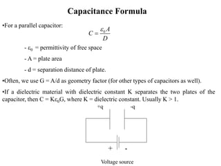
•The charge accumulated on capacitor plates is directly proportional to
voltage applied across the plates.
q V q = CV
where C is the constant of proportionality and is called capacitance (unit:
Farad).
•V-I characteristic of a capacitor is obtained by computing
•Alternatively, integrating the above equation w.r.t. time, and rearranging
terms, we get
[ ]
d
q CV
dt
dq dv
C
dt dt
( )
dv
I t C
dt
0
1
( ) ( )
t
V t I d
C
42. Capacitance Formula
+q -q
Voltage source
+ -
•For a parallel capacitor:
- e0 = permittivity of free space
- A = plate area
- d = separation distance of plate.
•Often, we use G = A/d as geometry factor (for other types of capacitors as well).
•If a dielectric material with dielectric constant K separates the two plates of the
capacitor, then C = Ke0G, where K = dielectric constant. Usually K > 1.
0 A
C
D
e
44. Capacitor Variations
•Ceramic capacitors
–very popular nonpolarized
capacitor
–small, inexpensive, but poor
temperature stability and poor
accuracy
–ceramic dielectric and a phenolic
coating
–often used for bypass and coupling
applications
•Electrolytic
–Aluminum, tantalum electrolytic
–Tantalum electrolytic capacitor has a
larger capacitance when compared to
aluminum electrolytic capacitor
–Mostly polarized.
–Greater capacitance but poor tolerance
when compared to nonelectrolytic
capacitors.
–Bad temperature stability, high
leakage, short lives
Axial lead Radial lead
45. Capacitor Variations
•Mylar
–very popular, nonpolarized
–reliable, inexpensive, low
leakage
–poor temperature stability
•Mica
–extremely accurate, low leakage
current
–constructed with alternate layers of
metal foil and mica insulation,
stacked and encapsulated
–small capacitance
–often used in high-frequency
circuits (i.e. RF circuits)
46. Capacitor Reading Example —I
•Thus, we have a 0.1mF capacitor with ±10% tolerance.
4 5 12 7 6
10 10 pF=10 10 F=10 F=0.1 10 F=0.1μF
48. Variable Capacitors
•Devices that can be made to change
capacitance values with the twist of a
knob.
•Air-variable or trimmer forms
–Air-variable capacitor consists of two
sets of aluminum plates (stator and rotor)
that mesh together but do not touch.
Often used in frequently adjusted tuning
applications (i.e., tuning communication
receivers over a wide band of
frequencies).
–A trimmer capacitor is a smaller unit
that is designed for infrequent fine-tuning
adjustment (i.e., fine-tuning fixed-
frequency communications receivers,
crystal frequency adjustments, adjusting
filter characteristics)
49. Inductors
•For an ideal coil, magnetic flux is
proportional to current, so
I or LI
–L is constant of proportionality,
called inductance (unit: Henry,
Wb/Amp).
•So, now, the V-I characteristic of an
inductor is:
•The above V-I characteristics
demonstrate that the current through
an inductor can not be altered
instantaneously.
0
1
( ) ( )
t
I t V d
L
( ) ( ) ( )
d d dI
V t LI L
dt dt dt
•Inductor is a passive energy storage
element that stores energy in the form
of magnetic field.
•Inductor characteristic is governed by
Faraday’s law:
–V = voltage induced across an
inductor
– = magnetic flux (unit: Webers,
Wb) through the coil windings (a coil
made using resistance-less wires) due
to current flowing through inductor.
( )
d
V t
dt
50. Inductor-Water Analogy —I
•Suppose a turbine is hooked up to the flywheel and water is supplied to the
turbine. The flywheel will start to move slowly. Eventually, the flywheel will
move at the same rate as the current.
•If the current alternates back and forth, the flywheel/turbine will take some
time to build up to the initial direction that the water wants to flow.
•As the current moves back and forth, the flywheel creates the extra
“resistance” to the change in current flow, but eventually the flywheel/turbine
will move in the same direction as the current flow.
51. Inductor-Water Analogy —II
•When switch S contacts A, the field generated by the applied positive voltage creates a reverse induced voltage that initially
resists current flow
•Based on the value of inductance, as the magnetic field reaches steady-state, the reverse voltage decays
•A collapsing field is generated when applied voltage is removed (switch S contacts B), creating a forward induced voltage
that attempts to keep current flowing
•Based on the value of inductance, as the magnetic field reaches zero steady-state, the forward voltage decays
Mechanical inertia and
inductor both resist
sudden change in their
state
52. Inductance of a Cylindrical Coil
•If number of turns per unit length
is “n”, then N= , so:
n
2 2 2
2 2 2
0
0 0
( )
n r
L n r n A
m
m m
–A = cross-sectional area of coil.
–If a magnetizable material forms
the core of coil, then permeability m
will be larger than m0.
2 2
0 N r
L
m
– = permeability of free space
– N = number of turns in coil
– = length of resistance-less wire
used in coil
– = radius of coil cross section.
r
0
m
54. Inductor Variations —II
•Antenna coil
–contains an iron core that
magnifies magnetic field
effects
–used to tune in ultra-
high-frequency signals, i.e.
RF signals
•Tuning coil
–screw-like “magnetic field
blocker” that can be adjusted to
select the desired inductance value
–used in radio receivers to select a
desired frequency.
55. Inductor Variations —III
•Chokes
–general-purpose inductors
that act to limit or suppress
fluctuating current.
–some use a resistor-like color
code to specify inductance
values.
•Toroidal coil
–resembles a donut with a
wire wrapping
–high inductance per
volume ratios, high quality
factors, self-shielding, can
be operated at extremely
high frequencies
57. Transformer
•Isolation
–acts exclusively as an
isolation device; does not
increase or decrease the
secondary voltage
–usually come with an
electrostatic shield
between the primary and
secondary. Often come
with a three-wire plug and
receptacle that can be
plugged directly into a
power outlet
•High Frequency
–often come with air
or powered-iron cores
–used for high
frequency applications,
i.e. matching RF
transmission lines to
other devices
(transmission line to
antenna)
•Audio
–used primarily to
match impedances
between audio
devices
–work best at audio
frequencies from
150Hz to 12kHz
–come in a variety of
shapes and sizes,
typically contain a
center tap
58. Kirchoff’s Voltage Law
•The algebraic sum of voltage around a
loop is zero.
•Assumption:
–Voltage drop across each passive
element is in the direction of current
flow.
1 2 3 4 0
V V V V
+ V2 -
- V4 +
+
V3
1
+
V1
-
I
59. Kirchoff’s Current Law
•Algebraic sum of all currents
entering and leaving a node is
zero.
•At node A:
•Current entering a node is
assigned positive sign. Current
leaving a node is assigned a
negative sign.
I1
I2
I3
A
1 2 3 0
I I I
60. Law of Voltage division
+ VR1
-
R1
+
V
R2
-
R2
-
Vs
+
I
1
1
1 2
R s
R
V V
R R
2
2
1 2
R s
R
V V
R R
61. Law of Current division
R1 R2
-
Vs
+
I
IR2
IR1
2
1
1 2
R
R
I I
R R
1
2
1 2
R
R
I I
R R