Downloaded 11 times


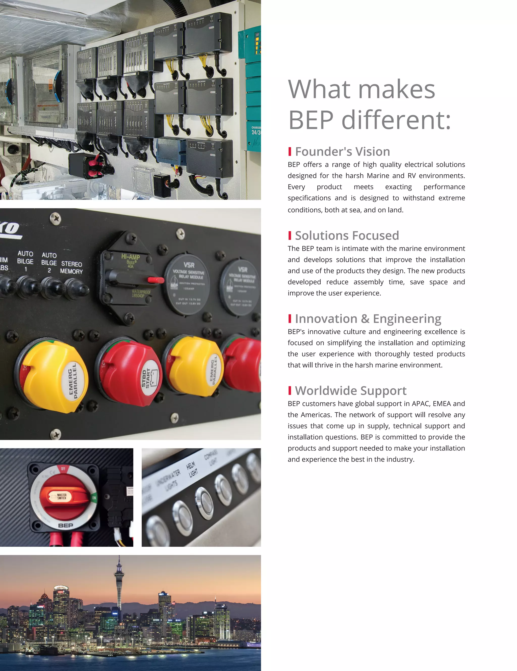


![58 CONNECTORS INSULATORS bepmarine.com
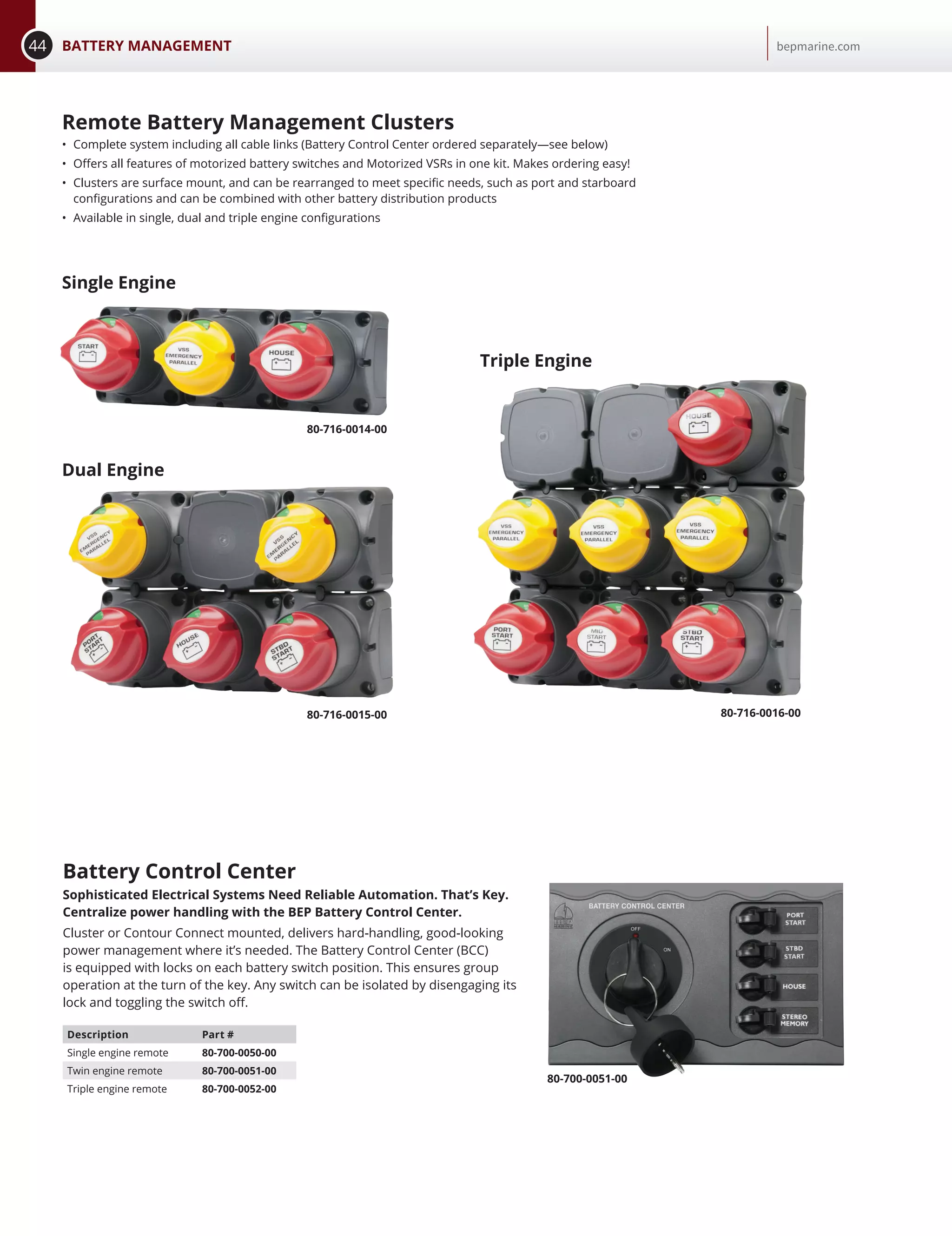
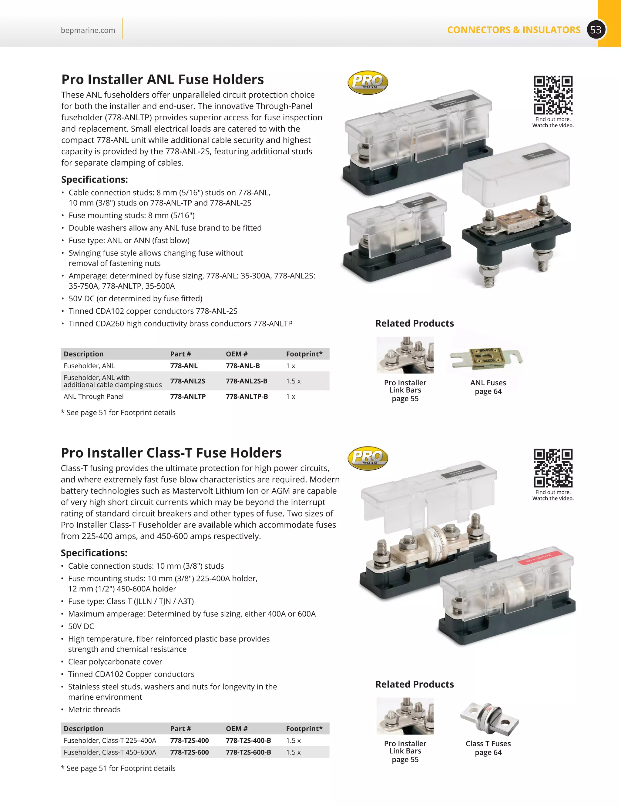
Pro Installer Clusters
Example shown below using Pro Installer distribution components, link bars and the award winning
EZ-Mount Battery Switch (page 32).
• Saves Time
• Saves Space
• Eliminates the need for jumper wires between products
• Common Interconnection heights allow “clustering” utilizing solid link bars
• Customize clusters for your application
Insulated Studs Covers
• Made with high temperature plastic bases
• Dual studs ideal for +ve / -ve connections, branch circuits, windlass or inverter installations.
• Stud covers push securely over the threaded stud covering to ABYC standards
• Covers supplied with display versions.
Single Studs
Part # OEM # Stud Size Polarity
IS-6MM-1R/DSP* IS-6MM-1R 1/4 / 6 mm Positive
IS-6MM-1/DSP* IS-6MM-1 1/4 / 6 mm Negative
— IS-10MM-1R 3/8 / 10 mm Positive
— IS-10MM-1 3/8 / 10 mm Negative
*Part #'s come with cover, OEM #'s do not.
Covers
Part # Description
ISC-10BK Double 10 mm
ISC-6-2 Double 6 mm
IS-6MM-1 IS-6MM-2 IS-10MM-2/LIS-10MM-2
ISC-10BK ISC-6-2
IS-10MM-1 IS-10MM-1R
Dual Studs
Part # OEM # Stud Size
IS-6MM-2/DSP* IS-6MM-2 2 x [1/4 / 6 mm]
— IS-10MM-2 2 x [3/8 / 10 mm]
— IS-10MM-2/L 2 x [3/8 / 10 mm] with link plate
*Part #'s come with cover, OEM #'s do not.](https://image.slidesharecdn.com/bepmarinecatalog-170126034405/75/BEP-Marine-Catalog-58-2048.jpg)


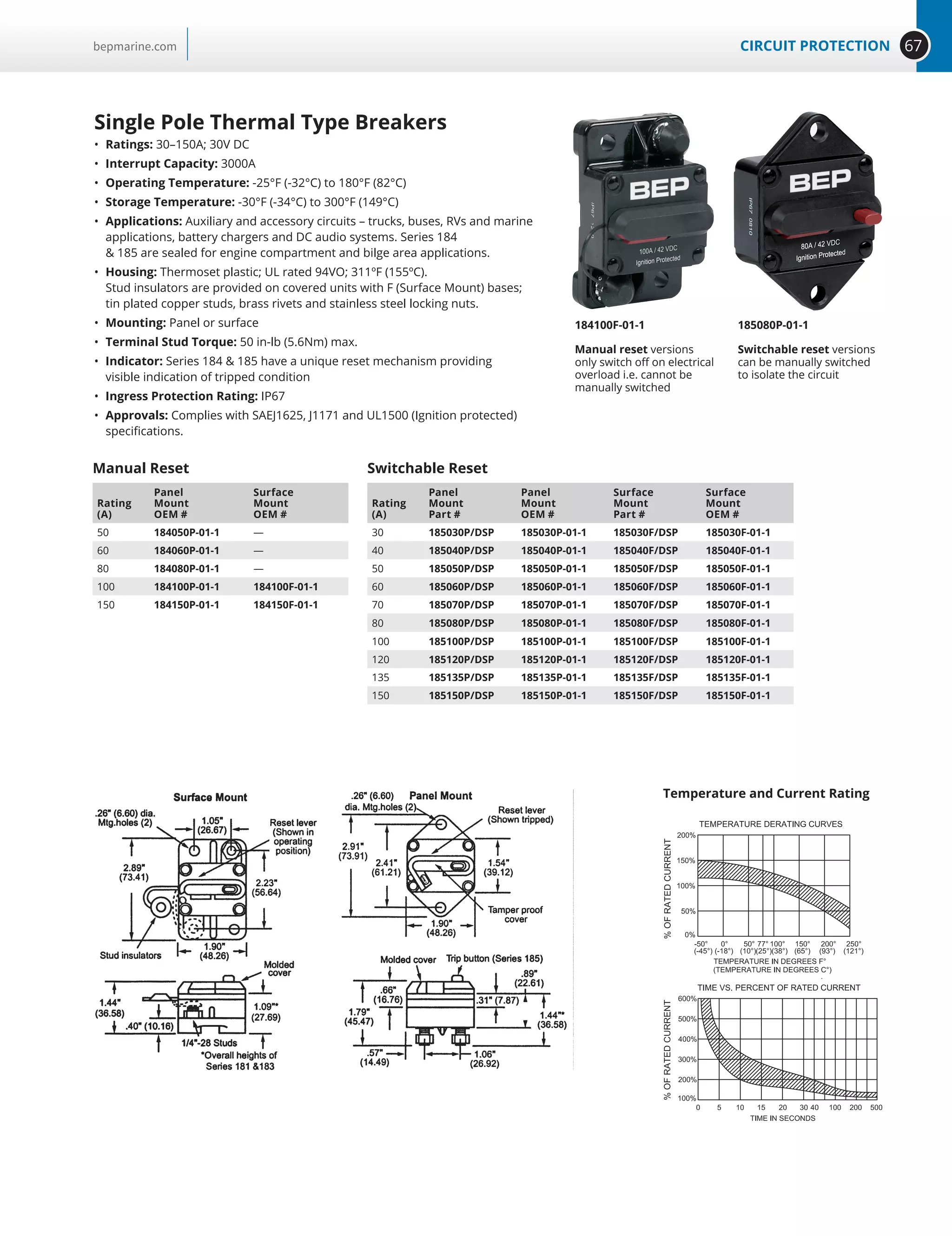

![69CIRCUIT PROTECTIONbepmarine.com
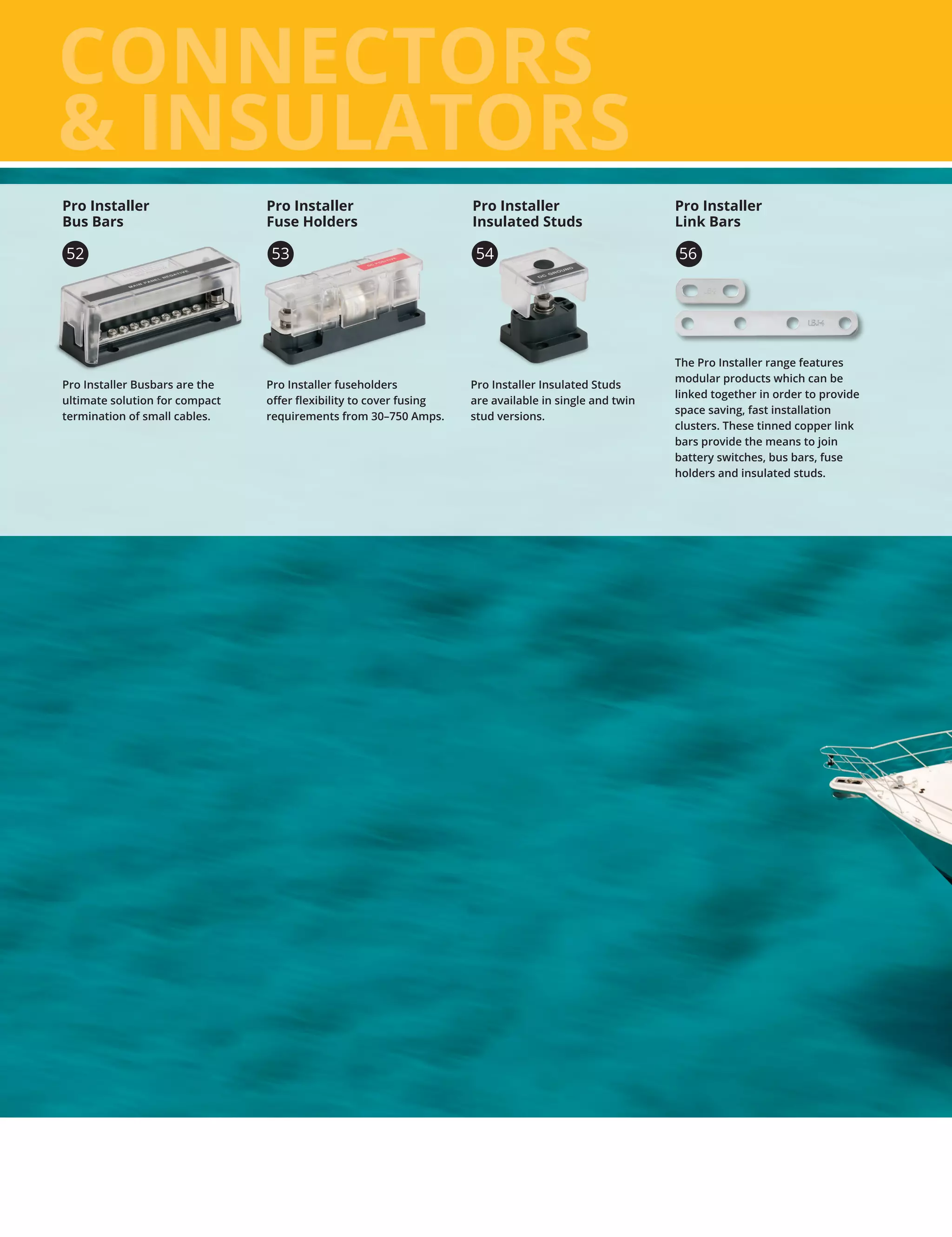
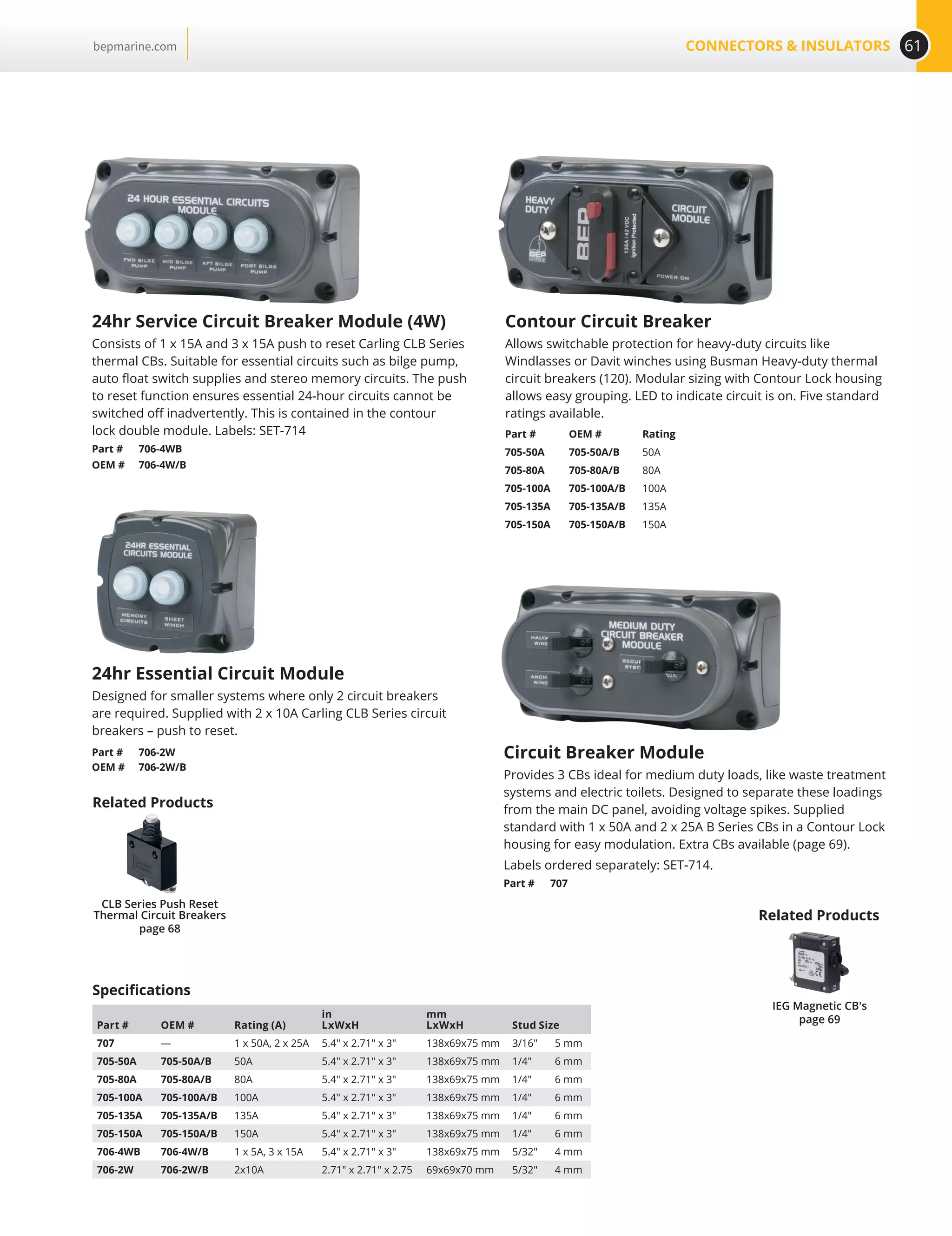
IEG Magnetic Circuit Breakers
IEG magnetic circuit breakers provide reliable circuit protection and
accurate circuit control for equipment in the international market place.
Designed using the latest in sensitive hydraulic magnetic technology, the IEG
line adapts itself to many applications and environments. They are ideal for
marine applications, data processing and business machines, as well as
medical instrumentation, broadcast equipment, vending and amusement
machines, military applications and wherever precision operation is
required. Temperature differences which affect fuses and other thermal
devices are not a concern. One important feature of this breaker line is a
‘trip free’ action, which means the circuit will trip in the presence of an
overload even though the handle is held in the ON position. The delay
mechanism senses the fault and the contacts open.
• Spacing compliance: IEC specification 601, 950; VDE 0804, 0805
• UL recognised; CSA certified; VDE 0660 approved; Part 101 CE compliant
• Available in single or double pole; triple pole available on special orders
IUL Magnetic Circuit Breakers
Provide reliable circuit protection and accurate circuit control for equipment
in the international market place. BEP uses the IUL range of circuit breakers
where current requirements exceed 50A and are within 100A. Available in
single and double pole with triple pole available on special orders.
CBS-50A-SP-IG
CBL-50A-SP
CBS-50A-DP
CBL-100A-DP
[3.56]
.140
[3.61]
.142
[47.22]
1.859
ON
OFF
[7.14]
.281
[49.28]
1.940
[36.78]
1.448
[10.97]
.432
[52.32]
2.060
M6 ISO THD
2x Ă.156
[3.96]
MAX.
[38.48]
1.515
[19.05]
.755
[5.59]
.220
[36.53]
1.438
[63.24]
2.490
[10.21]
.402
[52.32]
2.060
M3 ISO THD .750
[19.05]
Single Pole Double Pole
Note: Tolerance
.015 [.38]
unless noted.
Dimensions in
brackets [] are
millimeters.
Panel Mounting Detail:
Tolerance .013 unless noted.
Single pole
Rating
(A)
CBS-5A-SP 5
CBS-10A-SP 10
CBS-15A-SP 15
CBS-20A-SP 20
CBS-25A-SP 25
CBS-30A-SP 30
CBS-40A-SP 40
CBS-50A-SP-IG 50
Double pole
Rating
(A)
CBS-10A-DP 10
CBS-15A-DP 15
CBS-20A-DP 20
CBS-25A-DP 25
CBS-30A-DP 30
CBS-40A-DP 40
CBS-50A-DP 50
Triple pole
Rating
(A)
CBS-50A-TP / 50 50
D / Pold
trip coil pole
Volts
(V)
CBS-15A-DP-TC230 230
CBS-20A-DP-TC230 230
CBS-30A-DP-TC230 230
CBS-50A-DP-TC230 230
Single pole
Rating
(A)
CBL-50A-SP 50
CBL-60A-SP 60
CBL-75A-SP 75
CBL-100A-SP 100
Double pole
Rating
(A)
CBL-50A-DP 50
CBL-60A-DP 60
CBL-75A-DP 75
CBL-100A-DP 100
Triple pole
Rating
(A)
CBL-80A-TP 80
CBL-100A-TP 100
Compatible with BEP panels
Compatible with BEP panels.
Handle Lock
Image shows “handle lock” as used in all our battery management panels for
essential CBs to prevent accidental or unintended actuation of essential
circuits CB’s from either the “on” or “off” position. (ordered separately)
Part # 121-710-1101/1](https://image.slidesharecdn.com/bepmarinecatalog-170126034405/75/BEP-Marine-Catalog-69-2048.jpg)


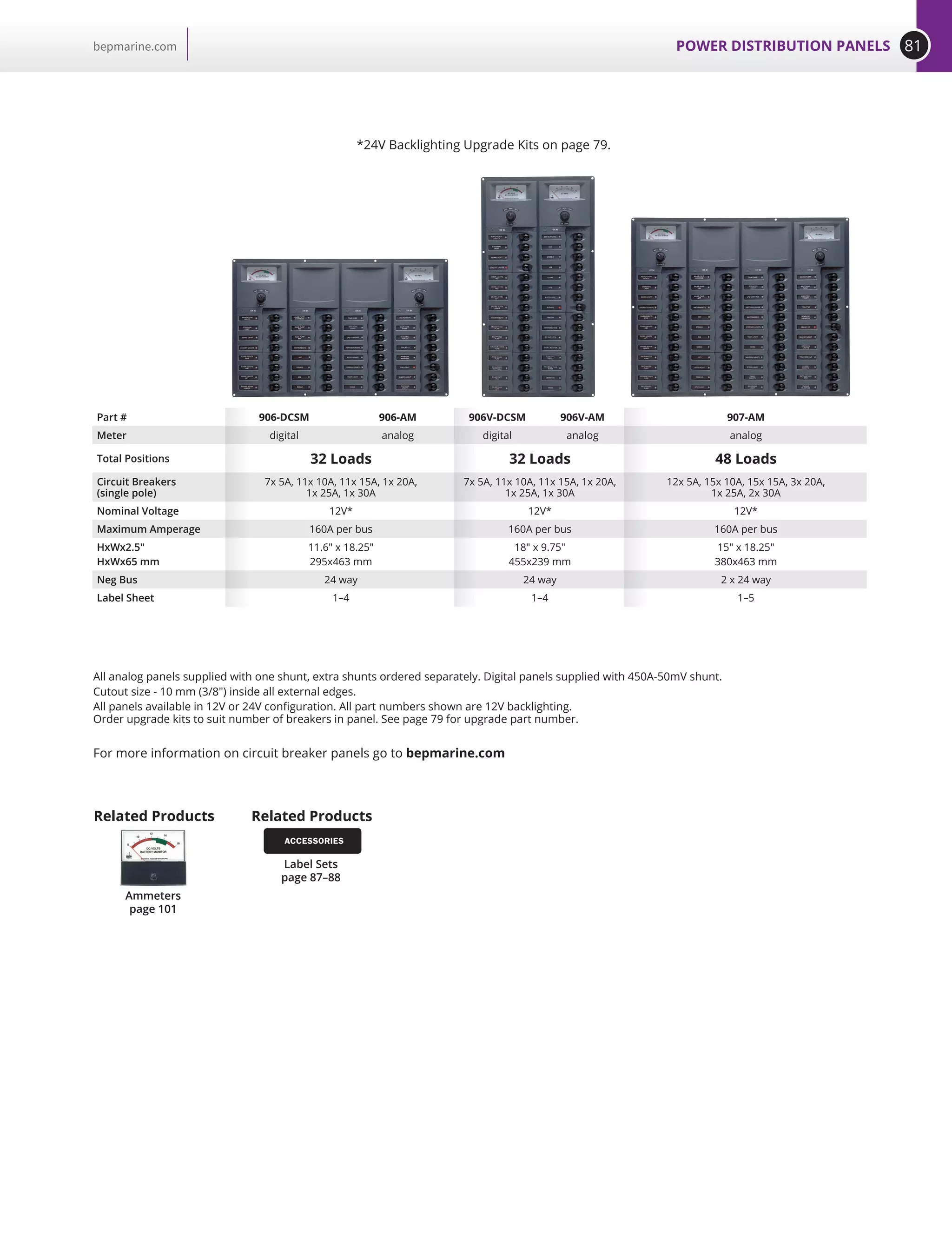
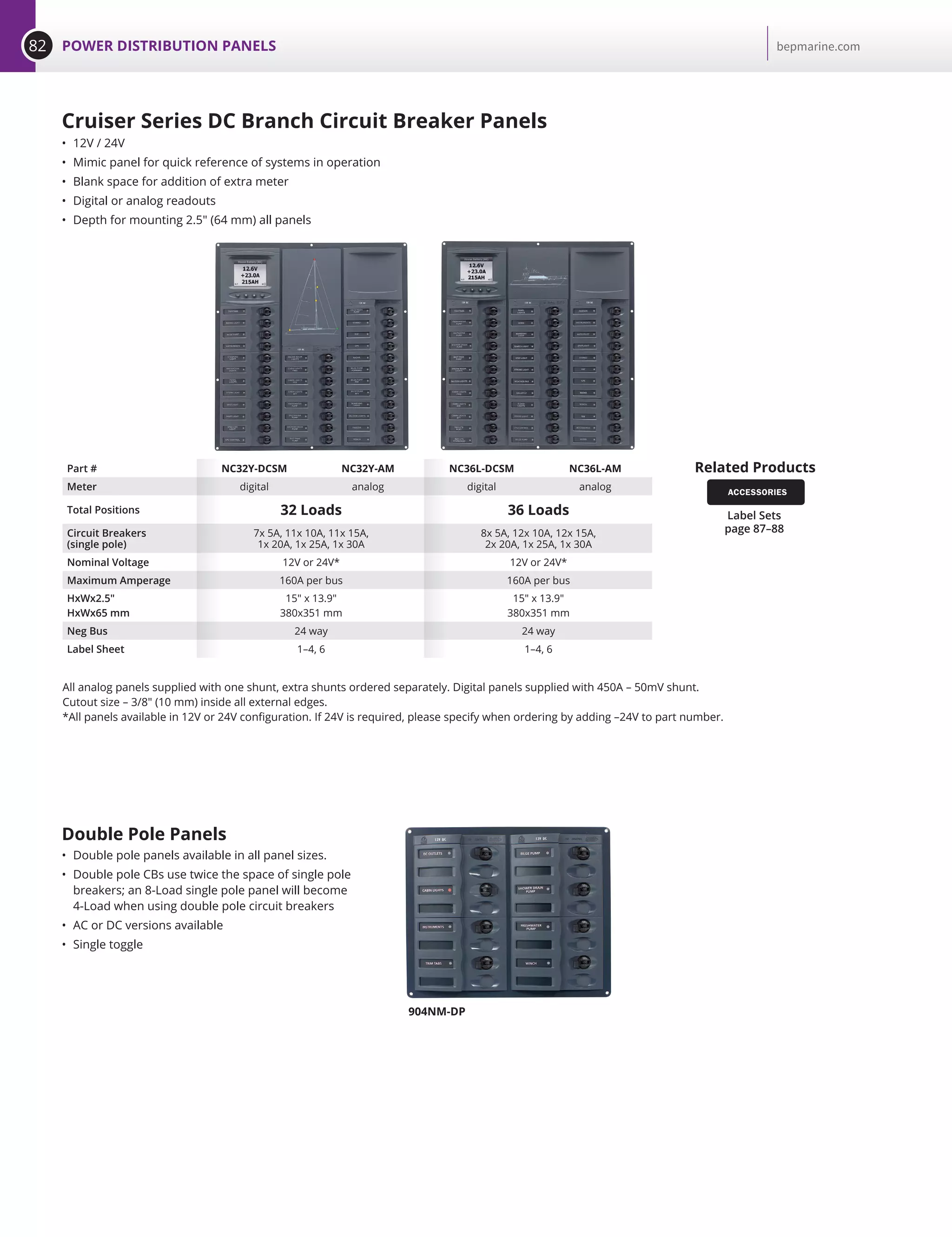
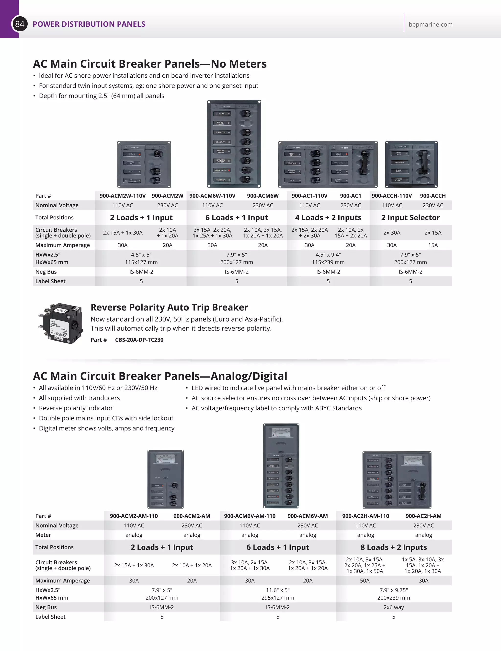
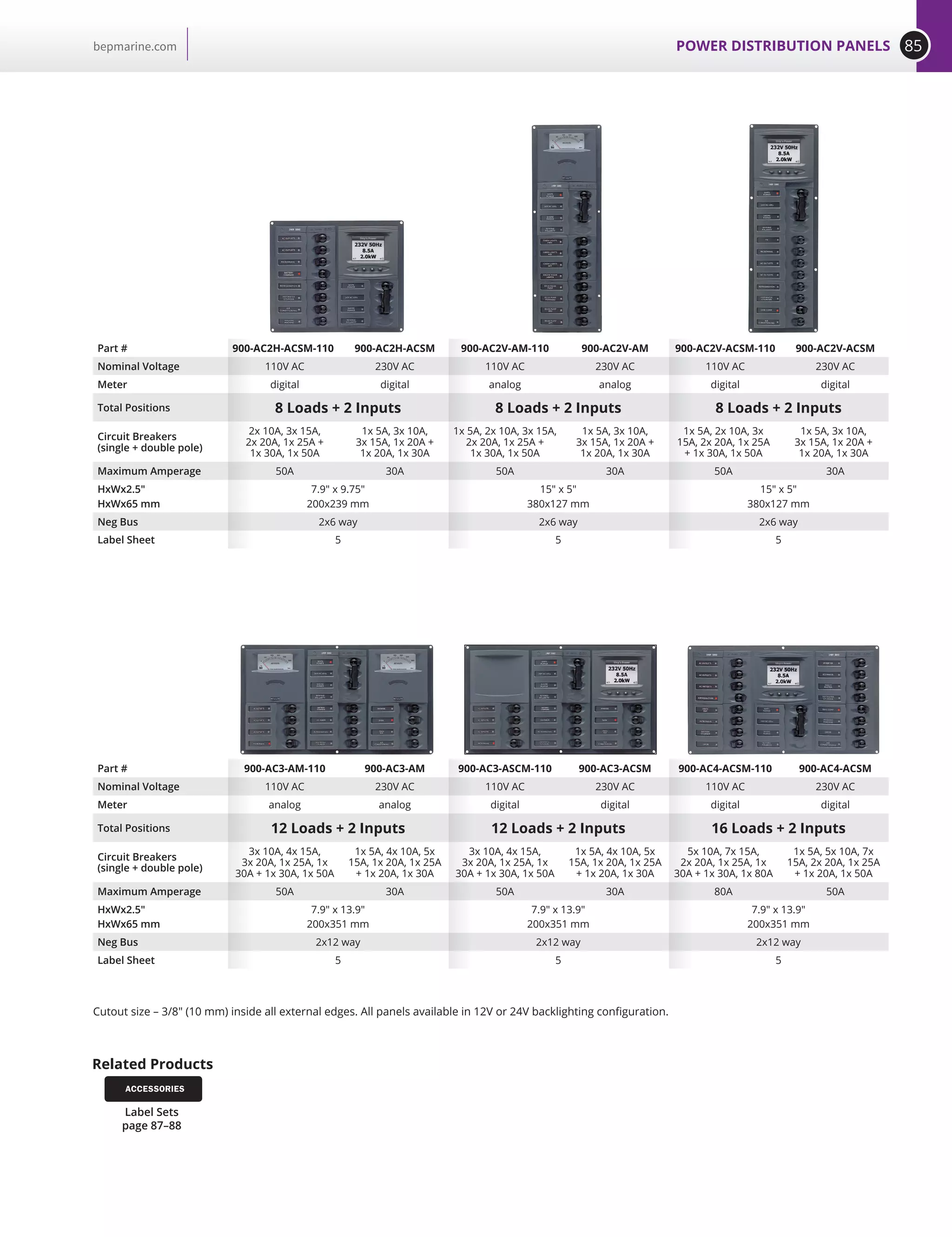
![76 POWER DISTRIBUTION PANELS bepmarine.com
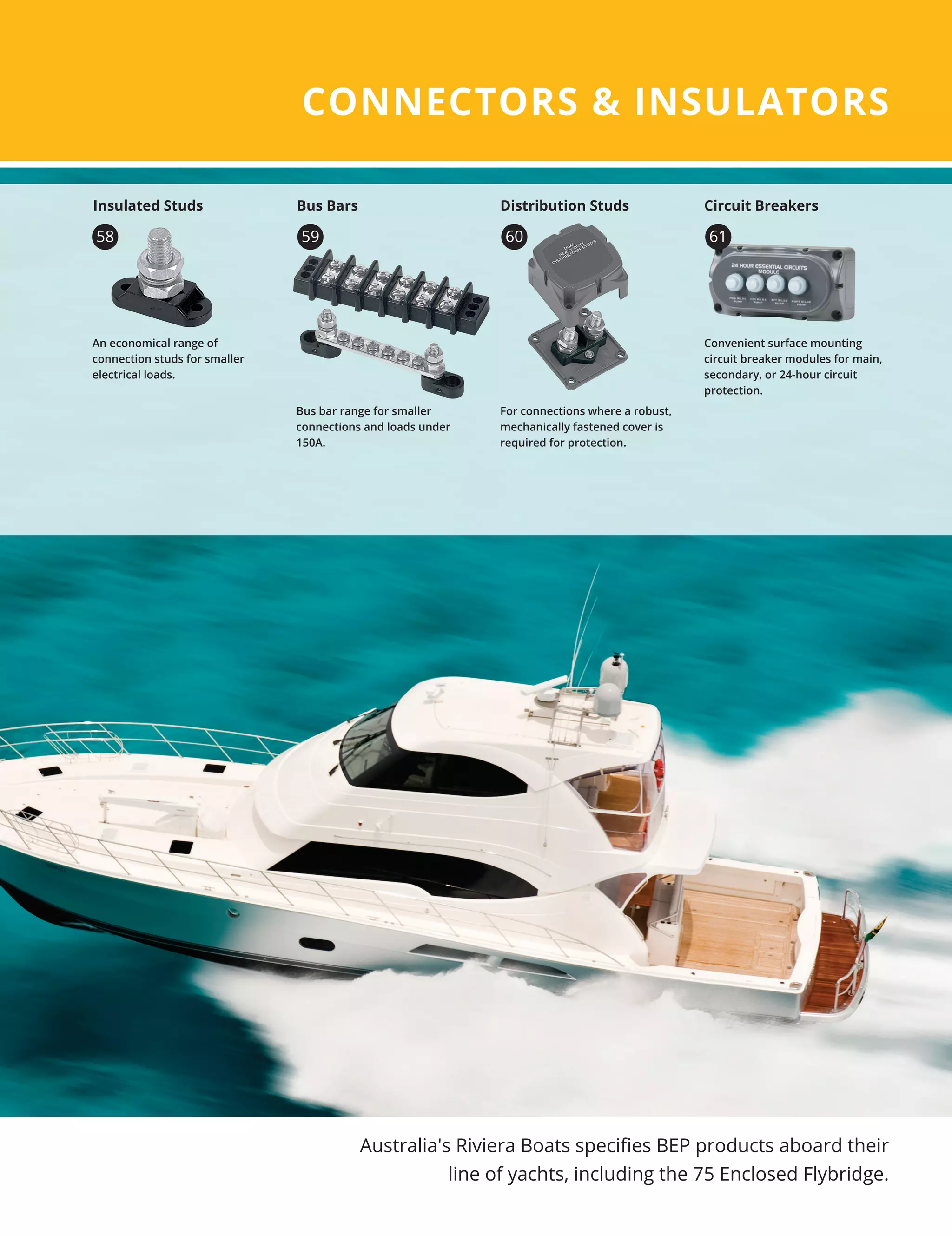
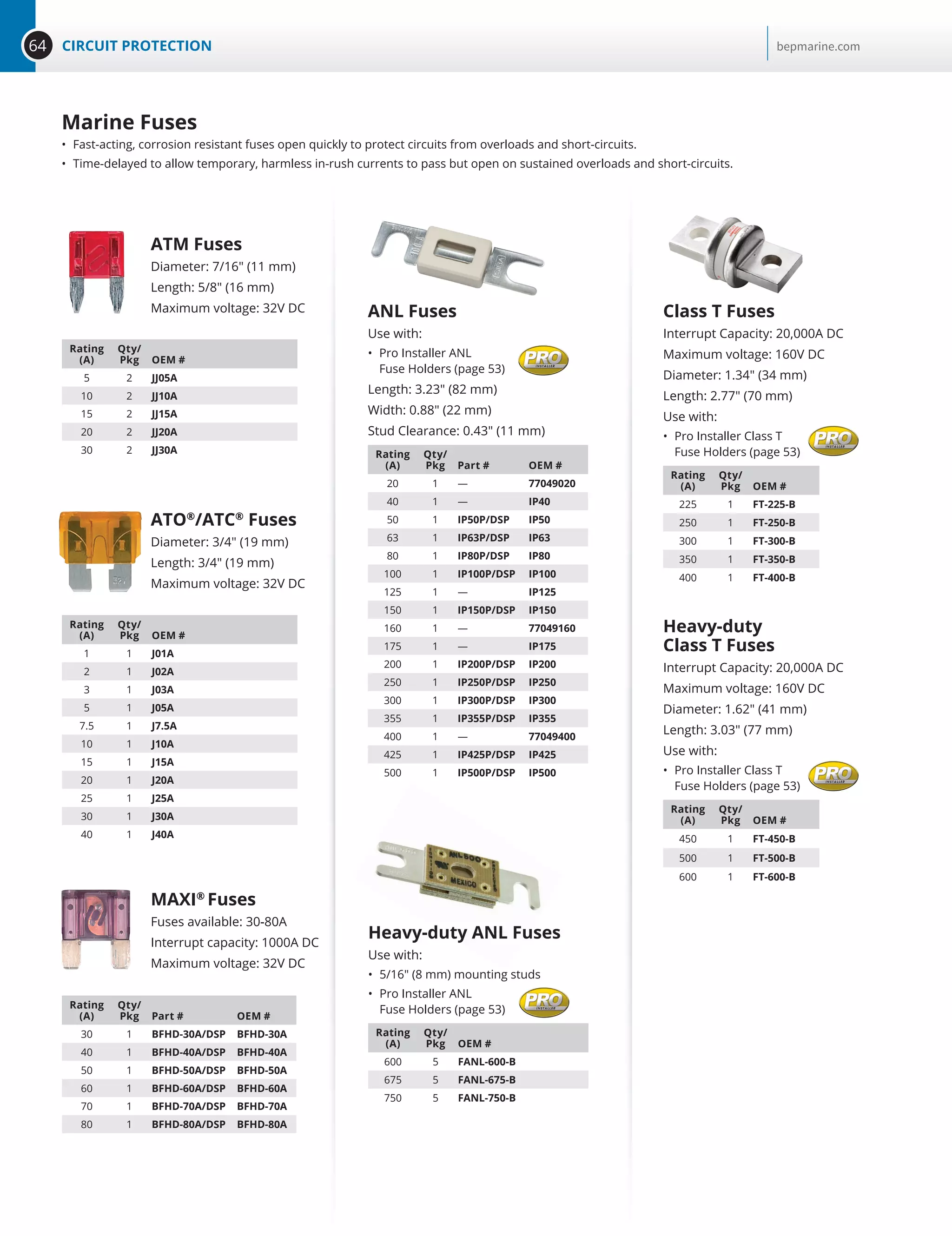
12V 24V Push-button Switches Buzzers with LED Ring
New push-button Switches Buzzers are built to last with their stainless steel components
and silver alloy contacts. The through panel mount switches are ideal for lighting, switch,
or dash panels, with colored rings that can be wired to either display power to the system
or switch back lighting. The product line includes both switches and warning buzzers
with LED light rings.
Features Benefits:
• Maximum switch current rating 5 amps
• IP67 environmental protection switches
• IP50 environmental protection buzzers
• 80 decibel buzzer sound intensity
• Warning buzzers flash red on alarm
LED +
NORMALLY OPEN
NORMALLY CLOSED
COMMON
LED -
TOP
O I
C -
+NONCTOP
22 [0.9]
10 (0.4) Max
2 [0.1] 37 [1.4]
19 [0.7] 25
[1.0]
25
[1.0]
10
[0.4]
12
[0.5]
12
[0.5]
22
[0.9]
22
[0.9]
22 [0.9]
10 (0.4) Max
2 [0.1] 54 [2.1]
19
[0.7]
PUSH-BUTTON SWITCHES
BUZZER UNITS
Description Color Part # OEM #
Latching On/Off Red 80-511-0001-00 80-511-0001-01
Latching On/Off Blue 80-511-0003-00 80-511-0003-01
Latching On/Off Green — 80-511-0011-01
Momentary (On)/Off Red 80-511-0002-00 80-511-0002-01
Momentary (On)/Off Blue 80-511-0004-00 80-511-0004-01
Momentary (On)/Off Green — 80-511-0012-01
Buzzer Red 80-511-0009-00 80-511-0009-01
Description Color Part # OEM #
Latching On/Off Red 80-511-0005-00 80-511-0005-01
Latching On/Off Blue 80-511-0007-00 80-511-0007-01
Momentary (On)/Off Red 80-511-0006-00 80-511-0006-01
Momentary (On)/Off Blue 80-511-0008-00 80-511-0008-01
Buzzer Red 80-511-0010-00 80-511-0010-01
12V 24V
Connection Cable
This 300 mm (12) cable simply pushes onto the back of the push
button switches and features 0.8 mm² / 18g cables for switch and
backlight connections that comply with ISO/ABYC. Other end is
stripped wire for easy connection.
Part # 80-511-0031-00
OEM # 80-511-0031-01
buzzer](https://image.slidesharecdn.com/bepmarinecatalog-170126034405/75/BEP-Marine-Catalog-76-2048.jpg)


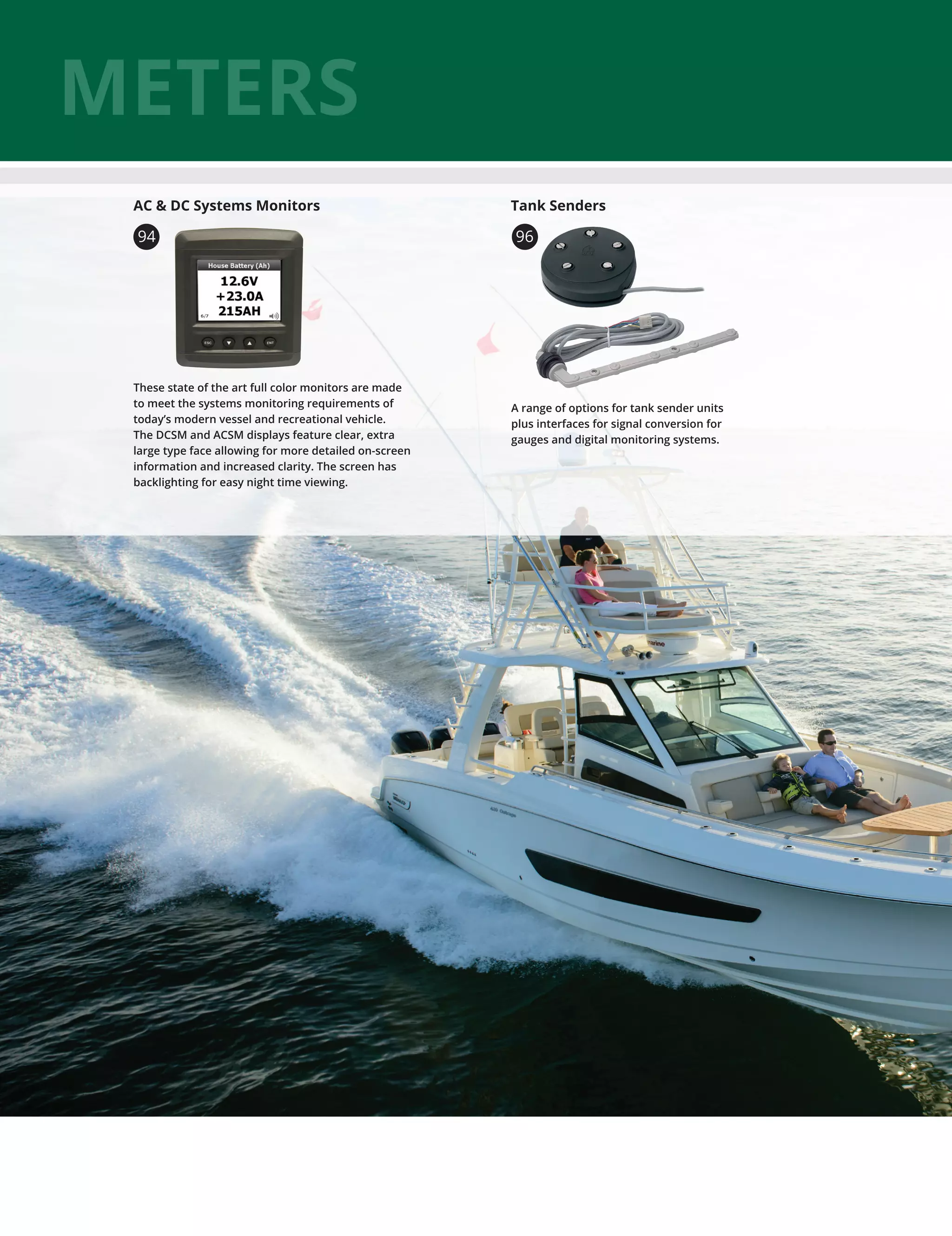


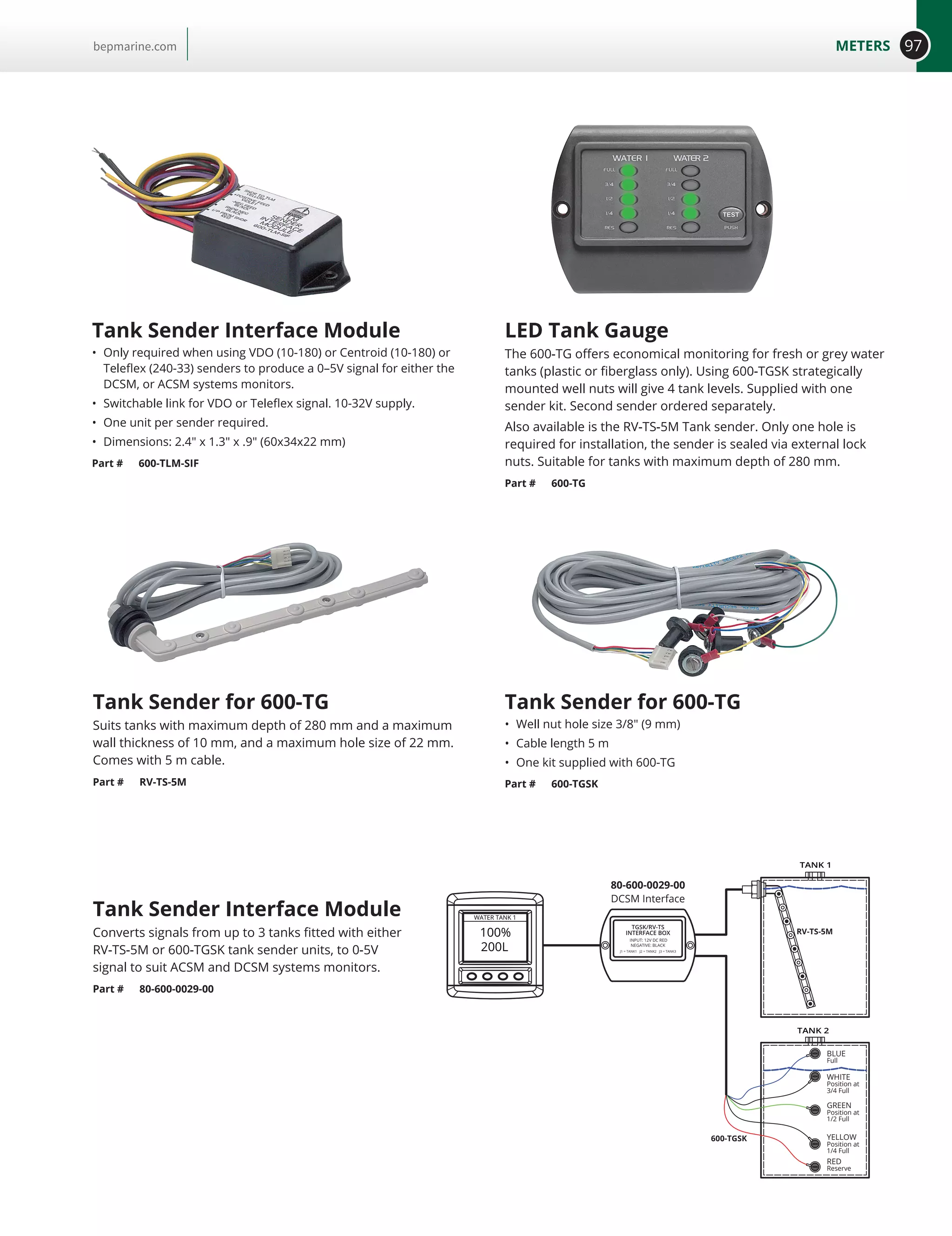
![96 METERS bepmarine.com
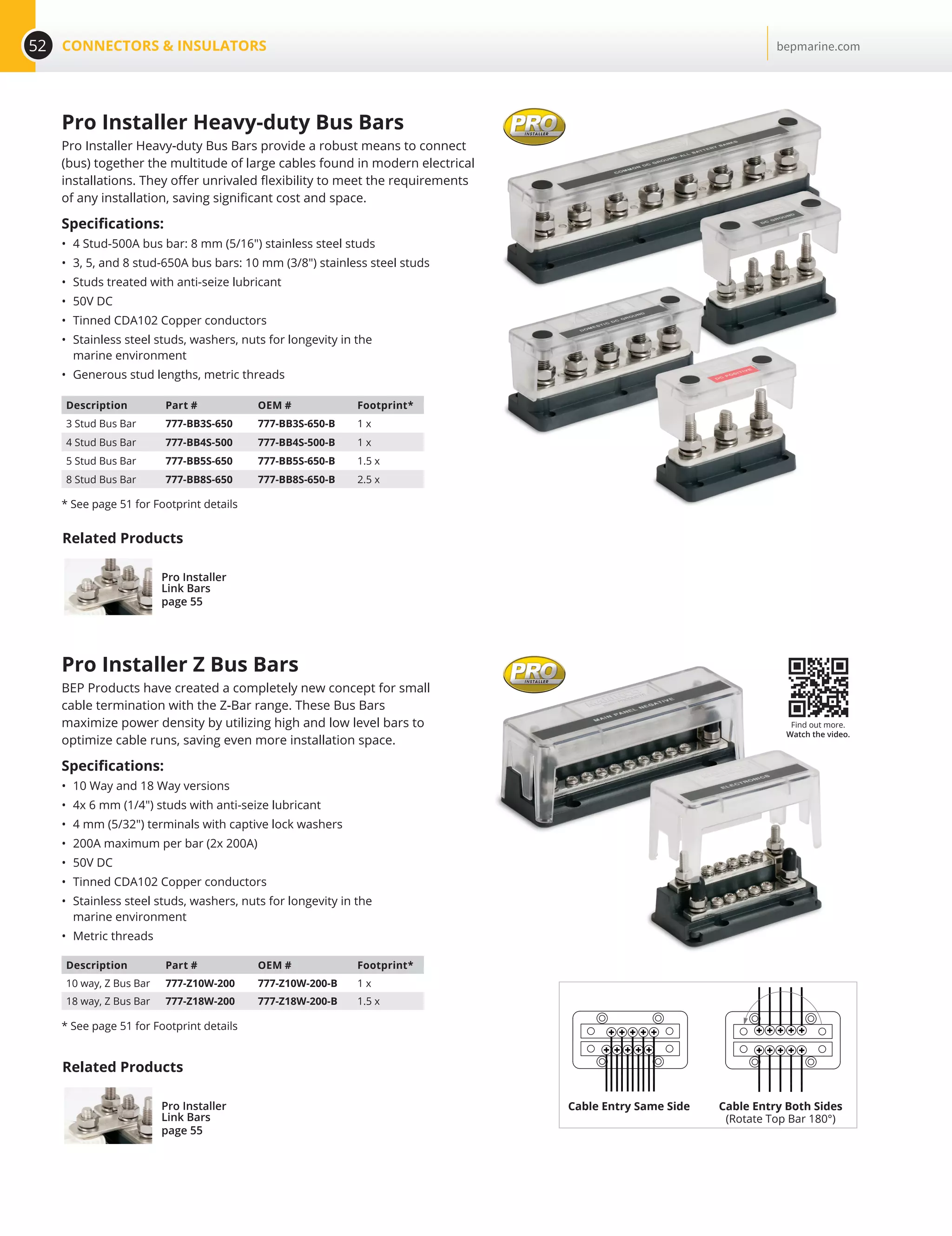
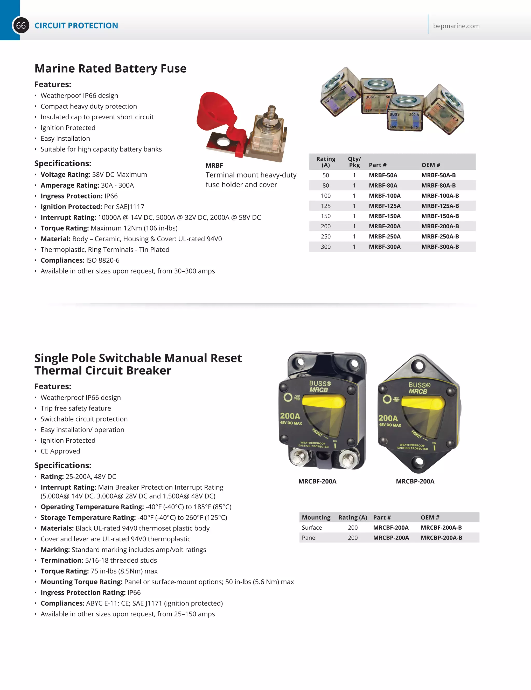
Ultrasonic Tank Sender—No Moving Parts
• Handles common outputs – 240-33, 10-180, Vetus 10-300 for analog resistive
gauges (not suitable for resistive digital gauges or CAN systems) and 0-5V tanks
from BEP, Teleflex, Faria, VDO and many other popular instrument brands.
(When connecting to non-adjustable gauges the TS1 must be pre-calibrated)
• Low Profile Design and standard SAE 5 hole mounting pattern,
allowing it to be retrofitted to practically all other sender brands
• Can be set for tank dimensions via computer using BEP Marine’s
proprietary TS1 software, avoiding experimental tank filling on site
• Connects directly to the DC systems monitors (80-600-0021-00
80-600-0022-00 page 94) when configured to a 0-5V output
• Is set for 0-2000 mm depth off the shelf (not suitable for tank
depths less than 200 mm) 8
• Operating voltage: 10–32V
• Current draw: 25 mA with 5V gauge output
• Measurement method: Acoustic sonic measurement
• Tank depth: 0–6.5 ft (2000 mm)
• Accuracy Distance: 0–6.5 ft (2000 mm) at 2 mm accuracy
• Environmental temperature: 39.2–149°F (4–65°C)
• Chemical resistance: Petrol, diesel, water, toilet chemicals
TS1 Programing Device
Part # TS1-PK
0.5M
95.43 [3 3/4]
19.64[3/4]
95.27 [3 3/4]
84.88[35/16]
BEP’s proprietary
Window’s based
software application
allows for TS1 senders
to be programmed
specific to tank shape,
size and fluid type via a
computer’s USB port.
Programming is a
simple process and can
be carried out
by downloading
free software from
bepmarine.com
and purchasing
a programming kit
TS1-PK.
Once programmed, the
specific tank
parameters are stored
in the non-volatile
memory of the TS1.
Find more detailed
information at
bepmarine.com
TS1](https://image.slidesharecdn.com/bepmarinecatalog-170126034405/75/BEP-Marine-Catalog-96-2048.jpg)


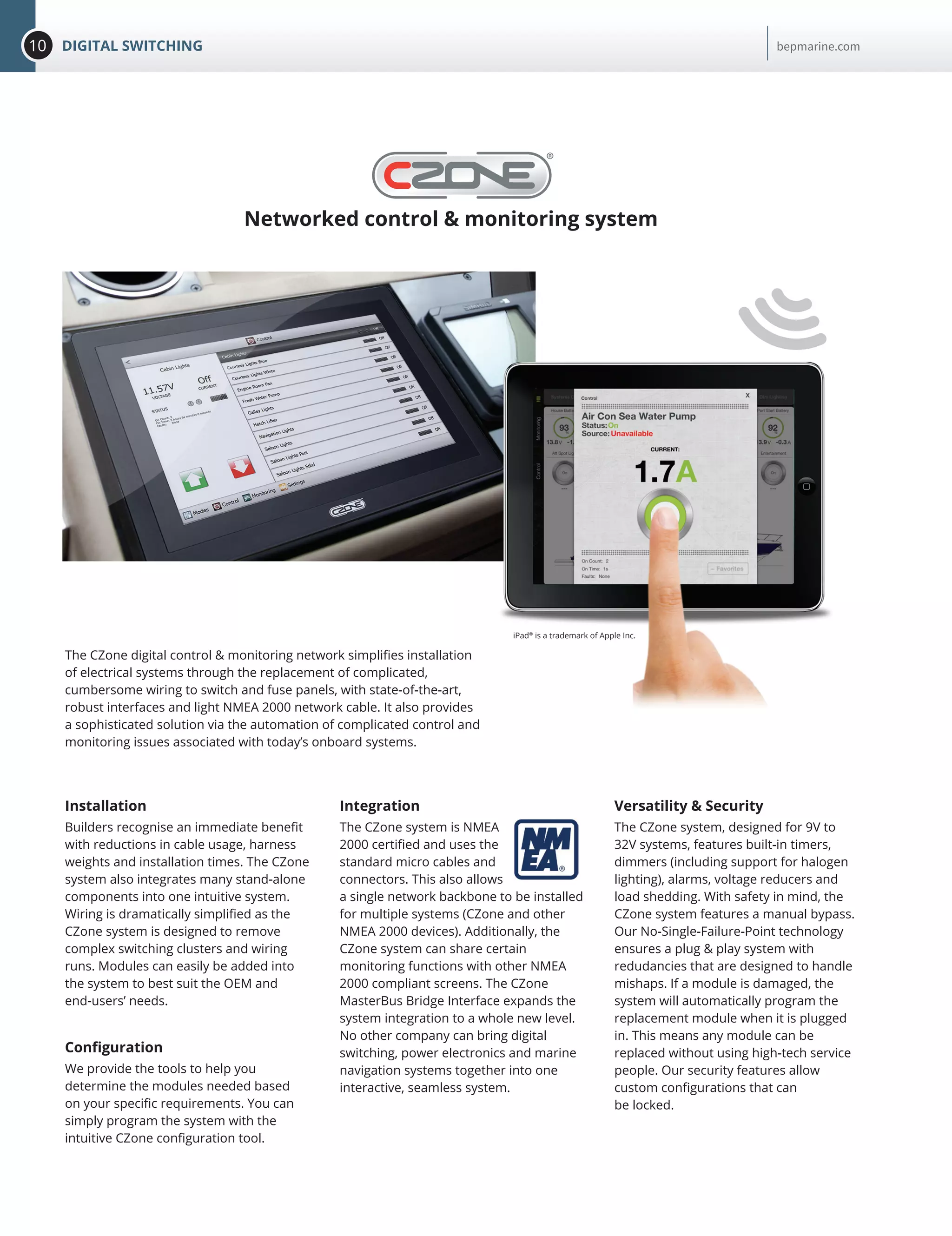
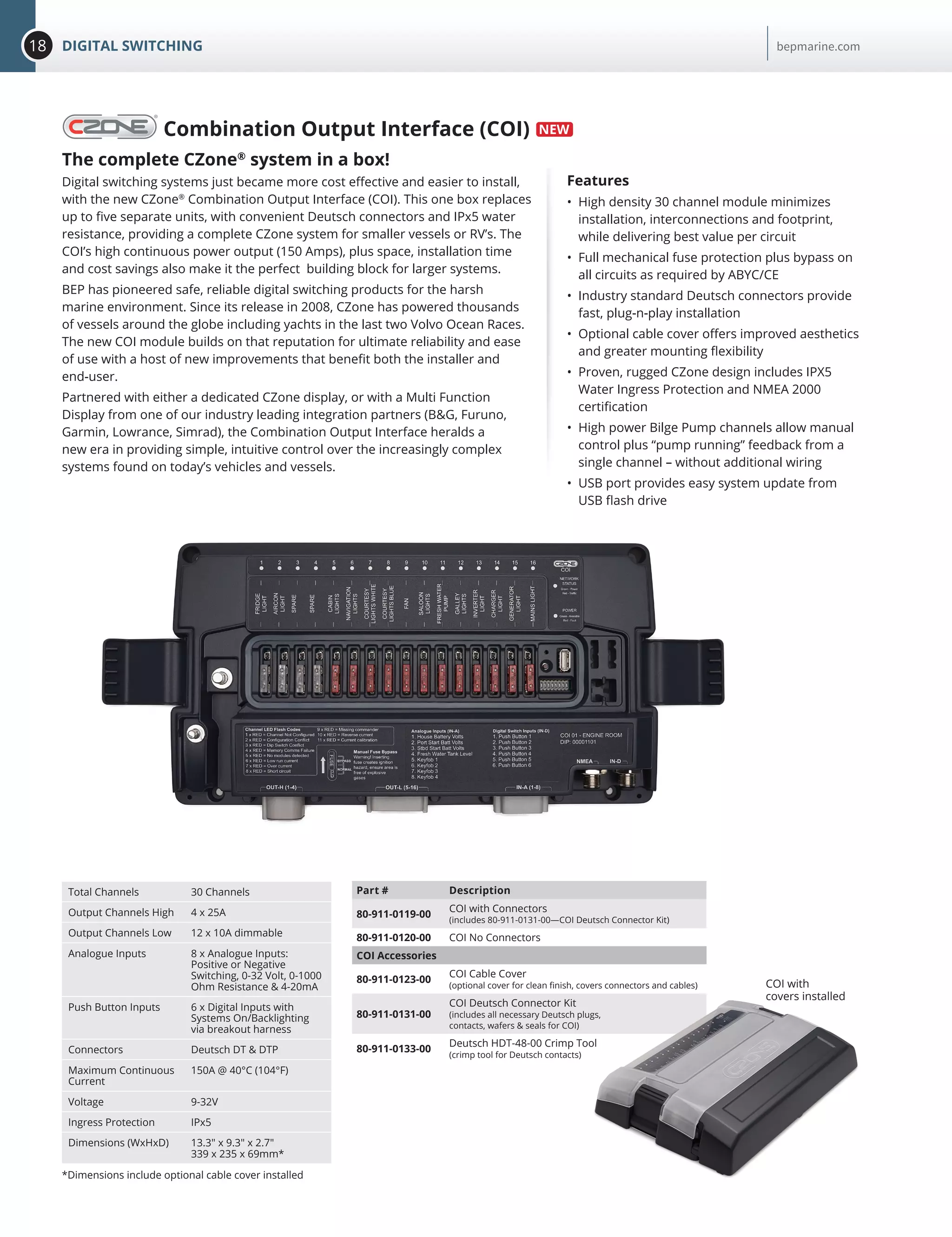
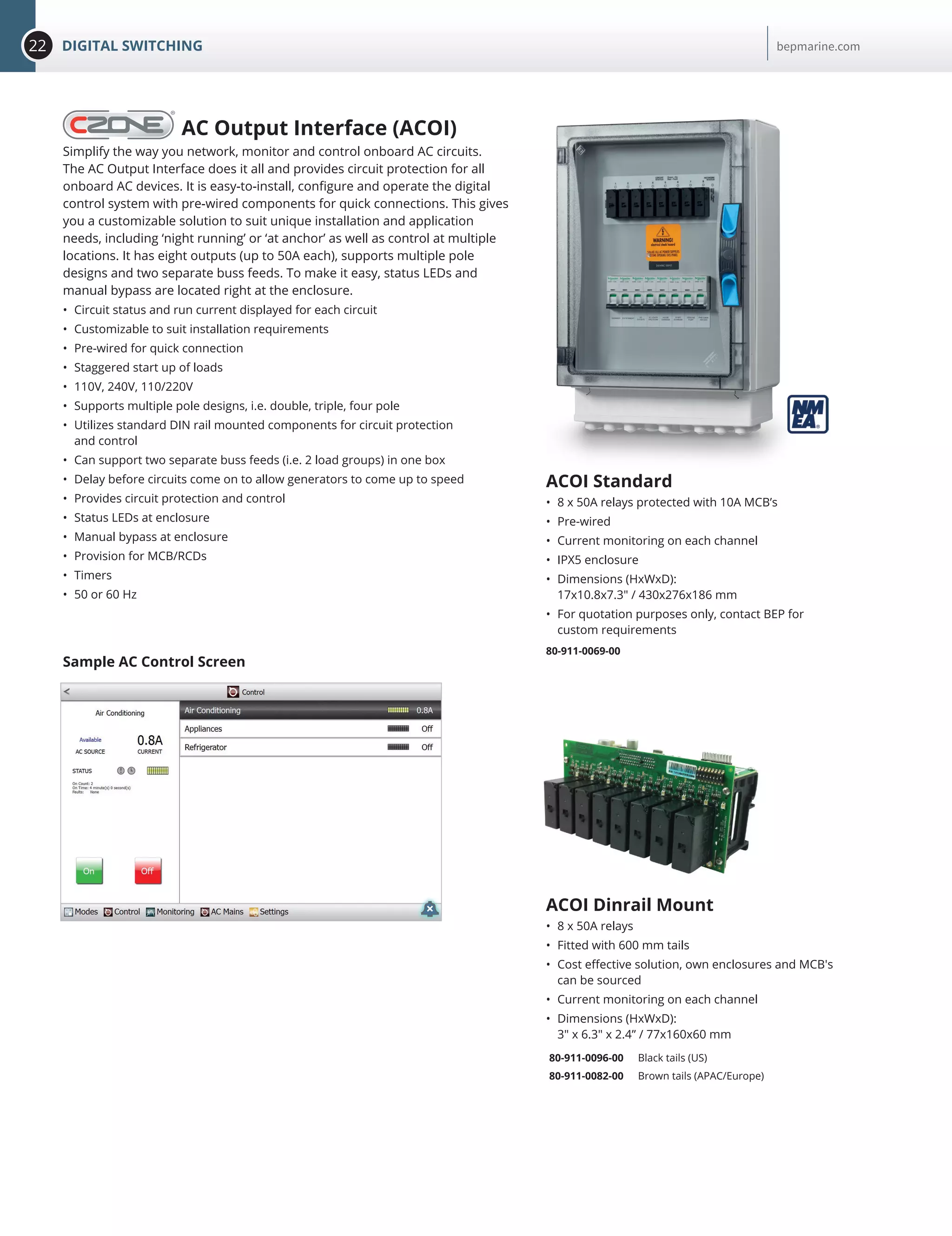
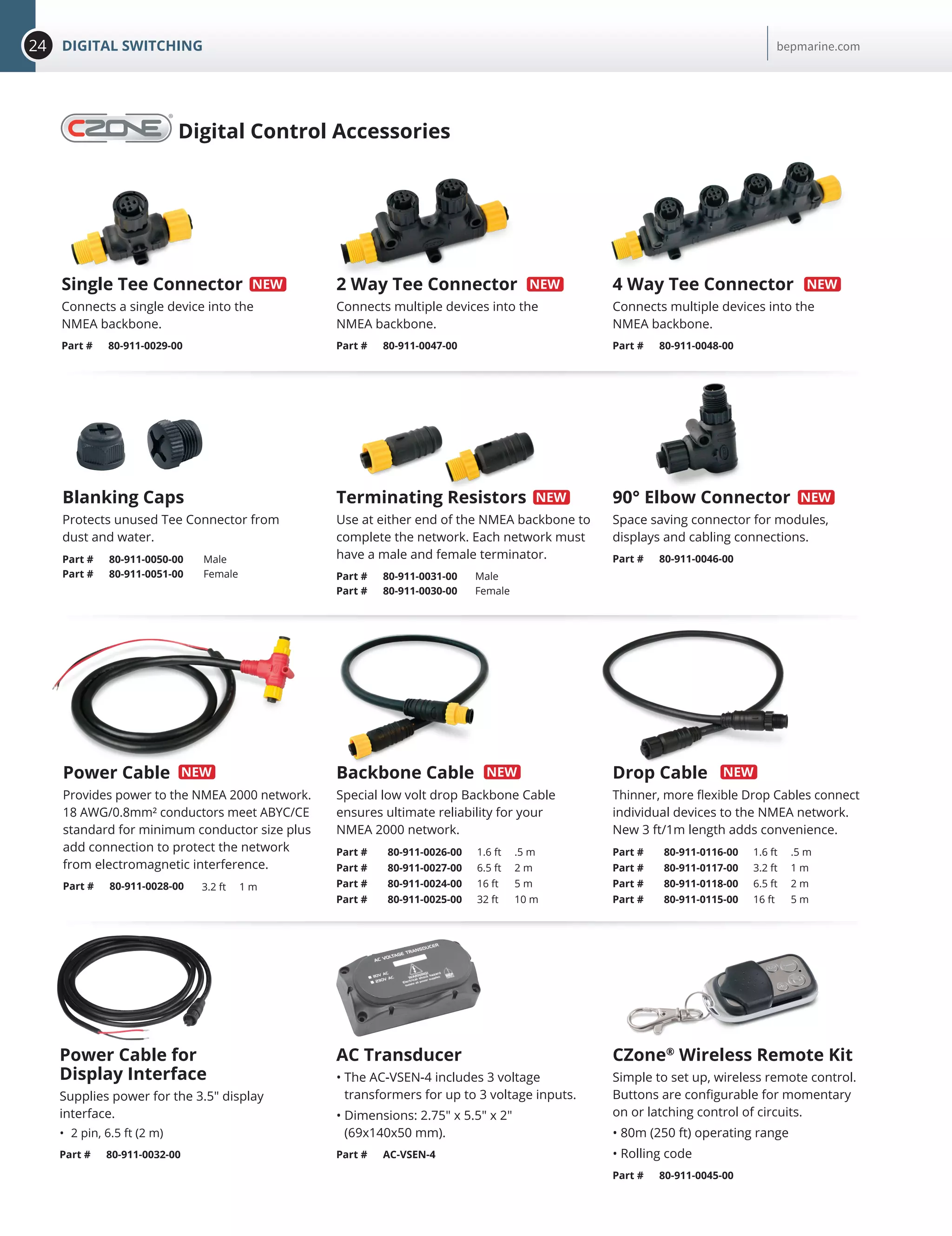
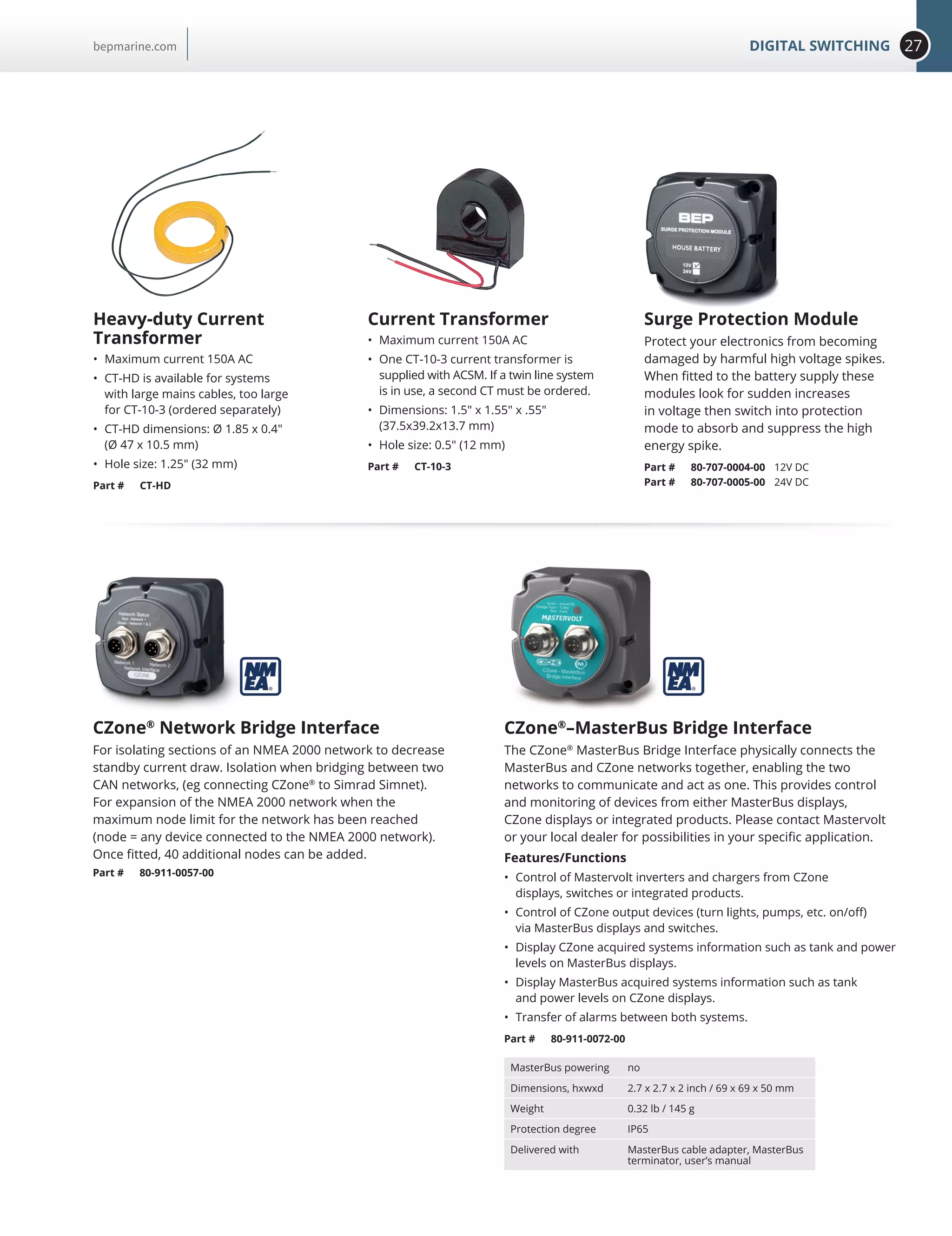
The document discusses electrical solutions from six leading marine and mobile electrical companies that are now working together to offer broader solutions. It summarizes various digital switching, battery management, connector, circuit protection, power distribution, and meter products available from the combined companies for applications in marine, emergency, industrial, and RV environments.


