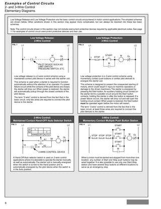
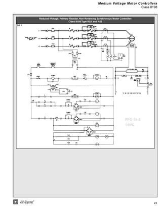
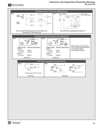
This document provides a wiring diagram and descriptions for a motor control system. It shows supply voltages connected to terminals A1 and B1/B3, a motor connected between terminals B1/B3 and A2, and control elements such as push buttons and overload relays connected in the control voltage circuit. Optional connections are provided for different supply voltages and control element configurations.


![64
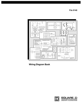
®
Reduced Voltage Controllers
Class 8640
2-Step, Part-Winding Type
Table 5 Motor Lead Connections
Part Winding Schemes Lettered Terminals in Panel Part Winding Schemes Lettered Terminals in Panel
A B C D E F A B C D E F
1/2 Wye or Delta 6 Leads T1 T2 T3 T7 T8 T9 2/3 Wye or Delta 6 Leads T1 T2 T9 T7 T8 T3
1/2 Wye 9 Leads [1] T1 T2 T3 T7 T8 T9 2/3 Wye 9 Leads [1] T1 T2 T9 T7 T8 T3
1/2 Delta 9 Leads [2] T1 T8 T3 T6 T2 T9 2/3 Delta 9 Leads [2] T1 T4 T9 T6 T2 T3
[1]
Connect terminals T4, T5 and T6 together at terminal box. [2]
Connect terminals T4 and T8, T5 and T9, T6 and T7 together in 3 separate pairs at terminal box.
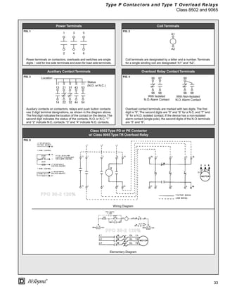
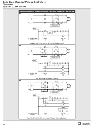
Part-Winding Reduced Voltage Controllers: Class 8640, Size 1PW-7PW
FIG. 1 FIG. 2
Size 1PW-4PW, 2-Step Part-Winding Controllers Size 5PW, 2-Step Part-Winding Controller
FIG. 3 FIG. 4
Size 6PW, 2-Step Part-Winding Controller Size 7PW, 2-Step Part-Winding Controller
➀ Disconnect means (optional): 2 required, 1 for each motor winding. ➁ See Table 5 for motor lead connections.](https://image.slidesharecdn.com/wiringdiagrambook-220914092729-afd51fcd/85/Wiring_Diagram_Book-pdf-68-320.jpg)


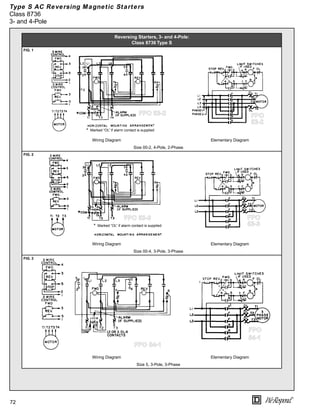


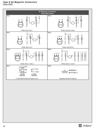
![81
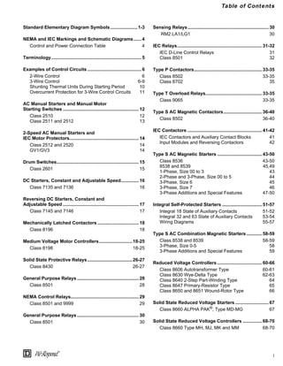
®
AC Lighting Contactors and Electronic Motor Brakes
Class 8903 and 8922
Panelboard Type Wiring:
Class 8903 Type PB, 30-225 A
FIG. 1 FIG. 3 FIG. 4
Control Circuit – Standard
FIG. 2
Control Circuit – 2-Wire Control
(Form R6)
Control Circuit – Long-Distance Control
(Form R62)
Power Circuit
QWIK-STOP® Electronic Motor Brake:
Class 8922
FIG. 5
Type ETB10, ETB18 and ETBS18 w/ Internal Braking Contactor
FIG. 6
Type ETB20-ETB800 and ETBS20-ETBS800
OFF
L
O
C
ON
L1
L2/N
CR2
L
O
C
CR1
L1
L2/N
CR2
CR1
OFF
ON
L1
T1
C
SO
+ –
L2
T2
L3
T3
L
O
C BR
SC
L = Line (common)
O = Open (unlatch)
C = Close (latch)
Omit middle pole
for 2-pole unit
CR
L
O
C
CR
L1
L2/N
CR
2-Wire
Pilot Device
L1
L2
L3
START
STOP
M
OL
T1
T2
T3
M
M
PLC
MOTOR
CUSTOMER CONTROL CIRCUIT
F1 F1
Xo Xo
ETB 10/18
When controlling electronic motor brake
ETB 10/18 with a PLC (programmable logic
control), terminals Xo-Xo must be jumpered.
[2]
[2]
M
F2 OL
M
F2 OL
M
F2 OL
L+
L1
L–
L2
B–
B+
B1
ETB 10/18
POWER CIRCUIT
F3
F3
24 VDC
+
–
[4]
Connection for ETBS only.
[4]
15 18
[1]
Contacts 15 and 18 close when
L1 and L2 are energized.
[1]
[3]
[3]
Semiconductor fuses.
[3]
L1
L2
L3
START
STOP
M
OL
T1
T2
T3
M
M
PLC
MOTOR
CUSTOMER CONTROL CIRCUIT
F1 F1
Xo Xo
ETB 20/800
When controlling electronic motor brake ETB 20/800 with a PLC
(programmable logic control), terminals Xo-Xo must be jumpered.
[2]
[2]
M
F2 OL
M
F2 OL
M
F2 OL
L+
L1
L–
L2
B–
B+
B1
ETB 20/800
POWER CIRCUIT
F3
F3
24 VDC
+
–
[4]
Connection for ETBS only.
[4]
15 18
[1]
Contacts 15 and 18 close when L1 and L2 are energized.
[1]
[3]
[3]
Semiconductor fuses.
[3]
M
25 28
B
B
B
B
QWIK-STOP is a registered trademark of Square D.](https://image.slidesharecdn.com/wiringdiagrambook-220914092729-afd51fcd/85/Wiring_Diagram_Book-pdf-85-320.jpg)
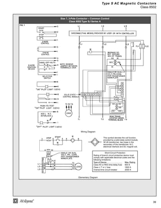
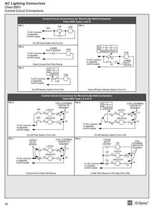
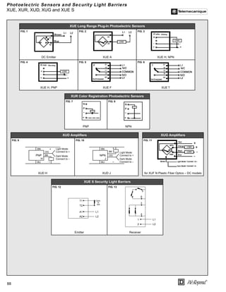
![82
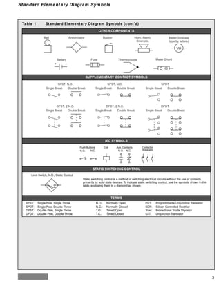
®
Electronic Motor Brakes, Duplex Motor Controllers and Fiber Optic Transceivers
Class 8922, 8941 and 9005
QWIK-STOP® Electronic Motor Brake: Class 8922 Type ETBC
FIG. 1
Type ETBC
AC Duplex Motor Controller: Class 8941 Fiber Optic Transceiver: Class 9005
FIG. 2 FIG. 3
Elementary Diagram for Duplex Motor Controller w/
Electric Alternator
Transceiver, Front View
FIG. 4
Location
L1
L2
L3
START
STOP
M
OL
T1
T2
T3
M
M
MOTOR
CUSTOMER CONTROL
CIRCUIT
F1 F1
To control electronic motor
brake ETBC with input B+/B–,
terminals 3 and 4 must be
jumpered.
[1]
M
F2 OL
M
F2 OL
M
F2 OL
T1/2
L1
T2/4
L2
ETBC
F3
F3
[1]
[2]
[2]
Semiconductor fuses.
[2]
B
B
M
PLC
24 VDC INPUT
+
–
1
2
3
4
5
6
7
B+ 9
B– 10
QWIK-STOP is a registered trademark of Square D.
A2
FIBER
A1
FIBER RELEASE
OUTPUT SETUP
GAIN
POWER
11
12
OUTPUT
14
86
OUTPUT
STATUS
LED SETUP
LED
FIBER
RELEASE
LEVER
GAIN
ADJ.
SCREW
INPUT
FIBER OPTIC
TRANSCEIVER
CLASS 9005 TYPE FT
FIBER OPTIC
PUSH BUTTON,
SELECTOR SWITCH,
LIMIT SWITCH, ETC.
FIBER OPTIC CABLE
ELECTRICAL
CONNECTIONS
BOUNDARY SEAL TO BE IN
ACCORDANCE WITH ARTICLE
501-5 OF THE NATIONAL
ELECTRICAL CODE
HAZARDOUS LOCATIONS NONHAZARDOUS LOCATIONS
CLASS I GROUPS A, B, C & D
CLASS II GROUPS E, F & G
CLASS III
FIBER OPTIC CABLE](https://image.slidesharecdn.com/wiringdiagrambook-220914092729-afd51fcd/85/Wiring_Diagram_Book-pdf-86-320.jpg)

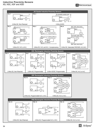


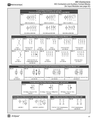
![90
®
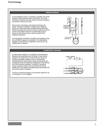
Limit Sw itches
Class 9007
Contact Forms for
Class 9007 Limit Switches
FIG. 1
Limit Switches:
Class 9007 Type C
FIG. 2 FIG. 3 FIG. 4
Types C52, C54
1-Pole
Type C62
2-Pole, Same Polarity Each Pole
Type C66
2-Pole, 2-Stage, Same Polarity Each Pole
FIG. 5
[1]
On CR switches, terminals 1-4 on left
side are for CW rotation and terminals
5-8 on right side are for CCW rotation.
FIG. 6
Types C68T5, C68T10, CR67T5 [1]
and CR67T10 [1]
2-Pole Neutral Position, Same Polarity Each Pole
Type C Reeds
Limit Switches:
Class 9007 Type XA
FIG. 7 FIG. 8
Type XA73 Reeds Type XA75 Reeds](https://image.slidesharecdn.com/wiringdiagrambook-220914092729-afd51fcd/85/Wiring_Diagram_Book-pdf-94-320.jpg)
![91
®
Limit Sw itches
Class 9007
Limit Switches:
Class 9007 Type AW
FIG. 1 FIG. 2
Type AW12 and AW14 Type AW18
FIG. 3
[1]
If lever arm is placed at same end of box as
conduit, N.O. contacts become N.C. and
vice versa.
FIG. 4
[1]
If lever arm is placed at same end of box as
conduit, N.O. contacts become N.C. and vice
versa.
FIG. 5
Type AW16
w/ Lever Arm Opposite Conduit Hole [1]
Type AW19
w/ Lever Arm Opposite Conduit Hole [1]
Type AW32, AW34, AW42
and AW44
FIG. 6 FIG. 7 FIG. 8
Type AW36 and AW46 Type AW38 and AW48 Type AW39 and AW49
Limit Switches:
Class 9007 Type SG – GATE GARDTM Switch
FIG. 9 FIG. 10
Type SGS1DK Type SGP1](https://image.slidesharecdn.com/wiringdiagrambook-220914092729-afd51fcd/85/Wiring_Diagram_Book-pdf-95-320.jpg)


![99
®
Enclosure Selection Guide
Table 6 Enclosures for Non-Hazardous Locations
Provides Protection Against
NEMA
Type 1
NEMA
Type 3 [1]
NEMA
Type 3R [1]
NEMA
Type 4 [2]
NEMA
Type 4X [2] Type 5
NEMA
Type 12 [3] Type 12K
NEMA
Type 13
Accidental contact w/ enclosed equipment Yes Yes Yes Yes Yes Yes Yes Yes Yes
Falling dirt Yes Yes Yes Yes Yes Yes Yes Yes Yes
Falling liquids and light splashing … Yes Yes Yes Yes … Yes Yes Yes
Dust, lint, fibers and flyings … … … Yes Yes Yes Yes Yes Yes
Hosedown and splashing water … … … Yes Yes … … … …
Oil and coolant seepage … … … … … … Yes Yes Yes
Oil and coolant spraying and splashing … … … … … … … … Yes
Corrosive agents … … … … Yes … … … …
Rain, snow and sleet [4]
… Yes Yes [5]
Yes … … … …
Windblown dust … Yes … [5]
Yes Yes … … …
[1]
Intended for outdoor use.
[2]
Intended for indoor and outdoor use.
[3]
Square D Industrial Control design NEMA Type 12 enclosures may be field modified for outdoor applications.
[4]
External operating mechanisms are not required to be operable when the enclosure is ice covered.
[5]
Square D Industrial Control design NEMA Type 4 enclosures provide protection against these environments.
Table 7 Enclosures for Hazardous Locations
Provides Protection Against Class [1] Group [1]
Enclosure
NEMA Type 7 NEMA Type 9
7B 7C 7D 9E 9F 9G
Hydrogen, manufactured gas I B Yes … … … … …
Ethyl ether, ethylene, cyclopropane I C Yes Yes … … … …
Gasoline, hexane, naphtha, benzine, butane, propane,
alcohol, acetone, benzol, natural gas, lacquer solvent
I D Yes Yes Yes … … …
Metal dust Il E … … … Yes … …
Carbon black, coal dust, coke dust Il F … … … … Yes …
Flour, starch, grain dust Il G … … … … Yes Yes
[1]
As described in Article 500 of the National Electrical Code.](https://image.slidesharecdn.com/wiringdiagrambook-220914092729-afd51fcd/85/Wiring_Diagram_Book-pdf-103-320.jpg)
![100
®
Conductor Ampacity and Conduit Tables
Based on 1993 National Electrical Code
Table 8 Conductor Ampacity based on NEC Table 310-16
COPPER CONDUCTORS ALUMINUM CONDUCTORS
Wire
Size
AWG
kcmil
75 °C (167 °F)
Conductor Insulation [1]
90 °C (194 °F)
Conductor Insulation [1]
Wire
Size
AWG
kcmil
75 °C (167 °F)
Conductor Insulation [1]
90 °C (194 °F)
Conductor Insulation [1]
Table
310-16
Ampacity
Insulated
Copper
THHW, THW,
RW, USE
THWN, XHHW
Table
310-16
Ampacity
Insulated
Copper
THHN, XHHW
Table
310-16
Ampacity
Insulated
Copper
THHW, THW,
USE
XHHW
Table
310-16
Ampacity
Insulated
Copper
THHN, XHHW
Conduit
3W
Conduit
4W [2]
Conduit
3W
Conduit
4W [2]
Conduit
3W
Conduit
4W [2]
Conduit
3W
Conduit
4W [2]
Conduit
3W
Conduit
4W [2]
Conduit
3W
Conduit
4W [2]
†14 20 … … 1/2 1/2 25 1/2 1/2 … … … … … … … … …
†12 25 … … 1/2 1/2 30 1/2 1/2 †12 20 … … 1/2 1/2 25 1/2 1/2
†10 35 … … 1/2 1/2 40 1/2 1/2 †10 30 … … 1/2 1/2 35 1/2 1/2
8 50 3/4 1 1/2 [3]
3/4 55 1/2 [3]
3/4 8 40 3/4 3/4 1/2 3/4 45 1/2 3/4
6 65 1 1 3/4 3/4 [4]
75 3/4 3/4 [4]
6 50 3/4 1 3/4 3/4 60 3/4 3/4
4 85 1 1-1/4 1 1 95 1 1 4 65 1 1 3/4 1 75 3/4 1
3 100 1-1/4 1-1/4 1 1-1/4 110 1 1-1/4 3 75 … … … … 85 … …
2 115 1-1/4 1-1/4 1 1-1/4 130 1 1-1/4 2 90 1 1-1/4 1 1-1/4 100 1 1-1/4
1 130 1-1/4 1-1/2 1-1/4 1-1/2 150 1-1/4 1-1/2 1 100 1-1/4 1-1/2 1-1/4 1-1/2 115 1-1/4 1-1/2
1/0 150 1-1/2 2 1-1/4 1-1/2 170 1-1/4 1-1/2 1/0 120 1-1/4 1-1/2 1-1/4 1-1/2 135 1-1/4 1-1/2
2/0 175 1-1/2 2 1-1/2 2 195 1-1/2 2 2/0 135 1-1/2 2 1-1/4 1-1/2 150 1-1/4 1-1/2
3/0 200 2 2 1-1/2 2 225 1-1/2 2 3/0 155 1-1/2 2 1-1/2 2 175 1-1/2 2
4/0 230 2 2-1/2 2 2 260 2 2 4/0 180 2 2 1-1 /2 2 205 1-1/2 2
250 255 2-1/2 2-1/2 2 2-1/2 290 2 2-1/2 250 205 2 2-1/2 2 2 230 2 2
300 285 2-1/2 3 2 2-1/2 320 2 2-1/2 300 230 2 2-1/2 2 2-1/2 255 2 2-1/2
350 310 2-1/2 3 2-1/2 3 350 2-1/2 3 350 250 2-1/2 3 2-1/2 3 280 2-1/2 3
400 335 3 3 2-1/2 3 380 2-1/2 3 400 270 2-1/2 3 2-1/2 2-1/2 [5]
305 2-1/2 2-1/2 [5]
500 380 3 3-1/2 3 3 430 3 3 500 310 3 3 2-1/2 3 350 2-1/2 3
600 420 3 3-1/2 3 3-1/2 475 3 3-1/2 600 340 3 3-1/2 3 3 385 3 3
700 460 3-1/2 4 3 3-1/2 520 3 3-1/2 700 375 3 3-1/2 3 3-1/2 420 3 3-1/2
750 475 3-1/2 4 3-1/2 4 535 3-1/2 4 750 385 3 3-1/2 3 3-1/2 435 3 3-1/2
800 490 3-1/2 4 3-1/2 4 555 3-1/2 4 800 395 … … … … 450 … …
900 520 4 5 3-1/2 4 585 3-1/2 4 900 425 … … … … 480 … …
1000 545 4 5 3-1/2 5 615 3-1/2 5 1000 445 3-1/2 4 3-1/2 4 500 3-1/2 4
[1]
Unless otherwise permitted in the Code, the overcurrent protection for conductor types marked
with an with an obelisk (†) shall not exceed 15 A for No. 14, 20 A for No. 12 and 30 A for No. 10
copper, or 15 A for No. 12 and 25 A for No. 10 aluminum after any correction factors for ambient
temperature and number of conductors have been applied
..
[2]
On a 4-wire, 3-phase wye circuit where the major portion of the load consists of nonlinear loads
such as electric discharge lighting, electronic computer/data processing, or similar equipment
there are harmonic currents present in the neutral conductor and the neutral shall be considered
to be a current-carrying conductor.
[3]
#8 XHHW copper wire requires 3/4" conduit for 3W.
[4]
#6 XHHW copper wire requires 1" conduit for 3Ø4W.
[5]
400 kcmil aluminum wire requires 3" conduit for 3Ø4W.
Ampacity Based on NEC® Table 310-16 — Allowable Ampacities of Insulated Conductors Rated 0-2000 Volts, Not More Than Three Conductors
in Raceway or Cable. Based on 30 °C Ambient Temperature. Trade Size of Conduit or Tubing Based on NEC Chapter 9, Table 1 and Tables 3A,
3B, 3C, 4 and 5B. Refer to Chapter 9 for Maximum Number of Conductors in Trade Sizes of Conduit or Tubing. Dimensions of Insulated Con-
ductors for Conduit Fill Determined from NEC Chapter 9 Tables 5 and 5A.
For information on temperature ratings of terminations to equipment, see NEC Section 110-14c. Underlined conductor insulation
types indicates ampacity is for WET locations. See NEC Table 310-13.
NEC is a Registered Trademark of the National Fire Protection Association.](https://image.slidesharecdn.com/wiringdiagrambook-220914092729-afd51fcd/85/Wiring_Diagram_Book-pdf-104-320.jpg)


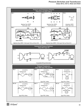
![103
®
Electrical Formulas
Table 13 Electrical formulas for Amperes, Horsepow er, Kilow atts and KVA
To find Single phase 3-phase Direct current
Kilowatts
I x E x PF
1000
I x E x 1.73 x PF
1000
I x F
1000
KVA
I x E
1000
I x E x 1.73
1000
—
Horsepower (output)
I x E x % Eff x PF
746
I x E x 1.73 x %Eff x PF
746
I x E x %Eff
746
Amperes when Horsepower is
known
HP x 746
E x %Eff x PF
HP x 746
1.73 x E x %Eff x PF
HP x 746
E x %Eff
Amperes when Kilowatts is
known
KW x 1000
E x PF
KW x 1000
1.73 x E x PF
KW x 1000
E
Amperes
KVA x 1000
E
KVA x 1000
1.73 x E
—
E=Volts l = Amperes %Eff = Percent efficiency PF = Power factor HP = Horsepower KVA = Kilovolt-Amps
Table 14 Ratings for 3-Phase, Single-Speed, Full-Voltage Magnetic Controllers
for Nonplugglng and Nonjogging Duty
Size of
Controller
Continous
Current Rating
(A)
Horsepower at [1]
Service-Limit
Current Rating
(A)
60 Hz 200 V 60 Hz 230 V 50 Hz 380 V
60 Hz
460 or 575 V
00 9 1-1/2 1-1/2 1-1/2 2 11
0 18 3 3 5 5 21
1 27 7-1/2 7-1/2 10 10 32
2 45 10 15 25 25 52
3 90 25 30 50 50 104
4 135 40 50 75 100 156
5 270 75 100 150 200 311
6 540 150 200 300 400 621
7 810 — 300 — 600 932
[1]
These horsepower ratings are based on typical locked-rotor current ratings. For motors having higher locked-rotor currents,
use a larger controller to ensure its locked-rotor current rating is not exceeded.
Average Efficiency and Power Factor Values of Motors:
When actual efficiencies and power factors of the motors to be controlled are not known, the following approximations may be used:
Efficiencies:
DC motors, 35 hp and less: 80% to 85%
DC motors, above 35 hp: 85% to 90%
Synchronous motors (at 100% PF): 92% to 95%
“Apparent” efficiencies (Efficiency x PF):
3-phase induction motors, 25 hp and less: 70%
3-phase induction motors above 25 hp: 80%
Decrease these figures slightly for single phase induction motors.](https://image.slidesharecdn.com/wiringdiagrambook-220914092729-afd51fcd/85/Wiring_Diagram_Book-pdf-107-320.jpg)
![104
®
Electrical Formulas
Table 15 Ratings for 3-Phase, Single-Speed, Full-Voltage Magnetic Controllers
for Plug-Stop, Plug-Reverse or Jogging Duty
Size of
Controller
Continous
Current Rating
(A)
Horsepower at [1]
Service-Limit
Current Rating
(A)
60 Hz 200 V 60 Hz 230 V 50 Hz 380 V
60 Hz
460 or 575 V
0 18 1-1/2 1-1/2 1-1/2 2 21
1 27 3 3 5 5 32
2 45 7-1/2 10 15 15 52
3 90 15 20 30 30 104
4 135 25 30 50 60 156
5 270 60 75 125 150 311
6 540 125 150 250 300 621
[1] These horsepower ratings are based on typical locked-rotor current ratings. For motors having higher locked-rotor currents,
use a larger controller to ensure its locked-rotor current rating is not exceeded.
Table 16 Pow er Conversions
From to kW to PS to hp to ft-lb/s
1 kW (kilowatt) = 1010 erg/s 1 1.360 1.341 737.6
1 PS (metric horsepower) 0.7355 1 0.9863 542.5
1 hp (horsepower) 0.7457 1.014 1 550.0
1 ft-lb/s (foot-pound per sec) 1.356 x 10⁻³ 1.843 x 10⁻³ 1.818 x 10⁻³ 1](https://image.slidesharecdn.com/wiringdiagrambook-220914092729-afd51fcd/85/Wiring_Diagram_Book-pdf-108-320.jpg)