Downloaded 735 times


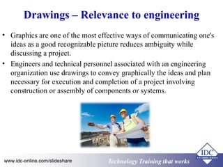
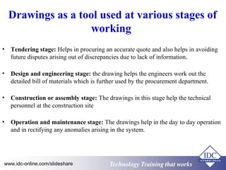


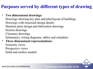
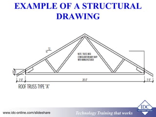


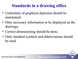
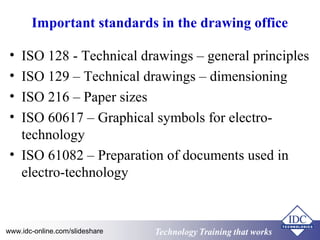


The document discusses the importance of drawings in engineering. It states that drawings are effective communication tools that reduce ambiguity. They are used at various stages of engineering projects from design to construction to operations. The document also outlines standards organizations for drawings and different types of drawings like schematics, technical drawings, and 3D models. It describes best practices for drawing offices, such as maintaining uniformity and using standard symbols and dimensions.


![553145181-Technical-Drawing-SBAjj[1].pdf](https://cdn.slidesharecdn.com/ss_thumbnails/553145181-technical-drawing-sba1-241117205357-f330e2d7-thumbnail.jpg?width=640&height=640&fit=bounds)
![553145181-Technicalqq-Drawing-SBA[1].pdf](https://cdn.slidesharecdn.com/ss_thumbnails/553145181-technical-drawing-sba1-241117205628-e2894348-thumbnail.jpg?width=640&height=640&fit=bounds)


