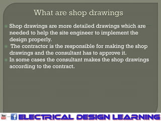
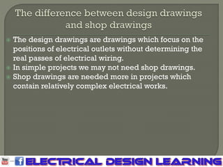
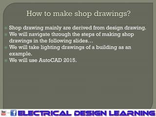
 What are shop drawings and why we need it?
 The difference between design drawings and shop
drawings.
 How to make shop drawings.
 The steps of making shop drawing.
 Shop drawings are more detailed drawings which are
needed to help the site engineer to implement the
design properly.
 The contractor is the responsible for making the shop
drawings and the consultant has to approve it.
 In some cases the consultant makes the shop drawings
according to the contract.
 The design drawings are drawings which focus on the
positions of electrical outlets without determining the
real passes of electrical wiring.
 In simple projects we may not need shop drawings.
 Shop drawings are needed more in projects which
contain relatively complex electrical works.
 Shop drawing mainly are derived from design drawing.
 We will navigate through the steps of making shop
drawings in the following slides…
 We will take lighting drawings of a building as an
example.
 We will use AutoCAD 2015.
 First we should copy the design drawing’s outlets into the
new file of the shop drawing.
 Then replace these blocks by new outlets which are used
in shop drawings.
 Edit the blocks of the switches by adding back boxes to
them, the same thing for the wall mounted lighting
fixtures.
 For the wall mounted outlets of the exhaust fans, replace
them with junction boxes.
 Start to make the wiring between the outlets and stick to
the circuits existed in the design drawings.
 Connect between each switch and its related outlets.
 Put the circuit number on each outlet.
 Also make the connection between each circuit and the
distribution board.
 Put the control letters on each outlet.
 Connect between each switch and its related outlets.
 Details are texts put on each plotted line to show its
circuit number, wire cross section and conduit diameter.
 Dimensions are put to show the distance between each
outlet and the nearest concrete column and the distance
between each two adjacent outlets.
 If the number of bends of each branch circuit achieved 3
bends, you should put a pull box.

Electrical shop drawing

  • 2.
     What areshop drawings and why we need it?  The difference between design drawings and shop drawings.  How to make shop drawings.  The steps of making shop drawing.
  • 3.
     Shop drawingsare more detailed drawings which are needed to help the site engineer to implement the design properly.  The contractor is the responsible for making the shop drawings and the consultant has to approve it.  In some cases the consultant makes the shop drawings according to the contract.
  • 4.
     The designdrawings are drawings which focus on the positions of electrical outlets without determining the real passes of electrical wiring.  In simple projects we may not need shop drawings.  Shop drawings are needed more in projects which contain relatively complex electrical works.
  • 5.
     Shop drawingmainly are derived from design drawing.  We will navigate through the steps of making shop drawings in the following slides…  We will take lighting drawings of a building as an example.  We will use AutoCAD 2015.
  • 6.
     First weshould copy the design drawing’s outlets into the new file of the shop drawing.  Then replace these blocks by new outlets which are used in shop drawings.  Edit the blocks of the switches by adding back boxes to them, the same thing for the wall mounted lighting fixtures.  For the wall mounted outlets of the exhaust fans, replace them with junction boxes.
  • 7.
     Start tomake the wiring between the outlets and stick to the circuits existed in the design drawings.  Connect between each switch and its related outlets.  Put the circuit number on each outlet.  Also make the connection between each circuit and the distribution board.  Put the control letters on each outlet.  Connect between each switch and its related outlets.
  • 8.
     Details aretexts put on each plotted line to show its circuit number, wire cross section and conduit diameter.
  • 9.
     Dimensions areput to show the distance between each outlet and the nearest concrete column and the distance between each two adjacent outlets.
  • 10.
     If thenumber of bends of each branch circuit achieved 3 bends, you should put a pull box.