Downloaded 2,400 times
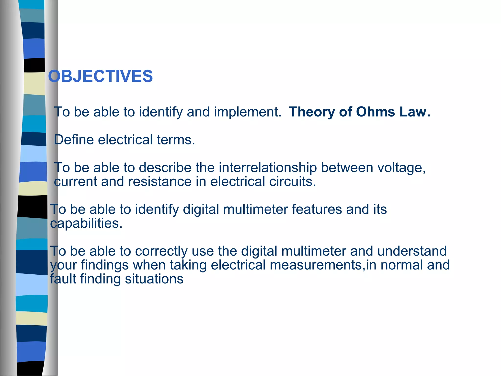
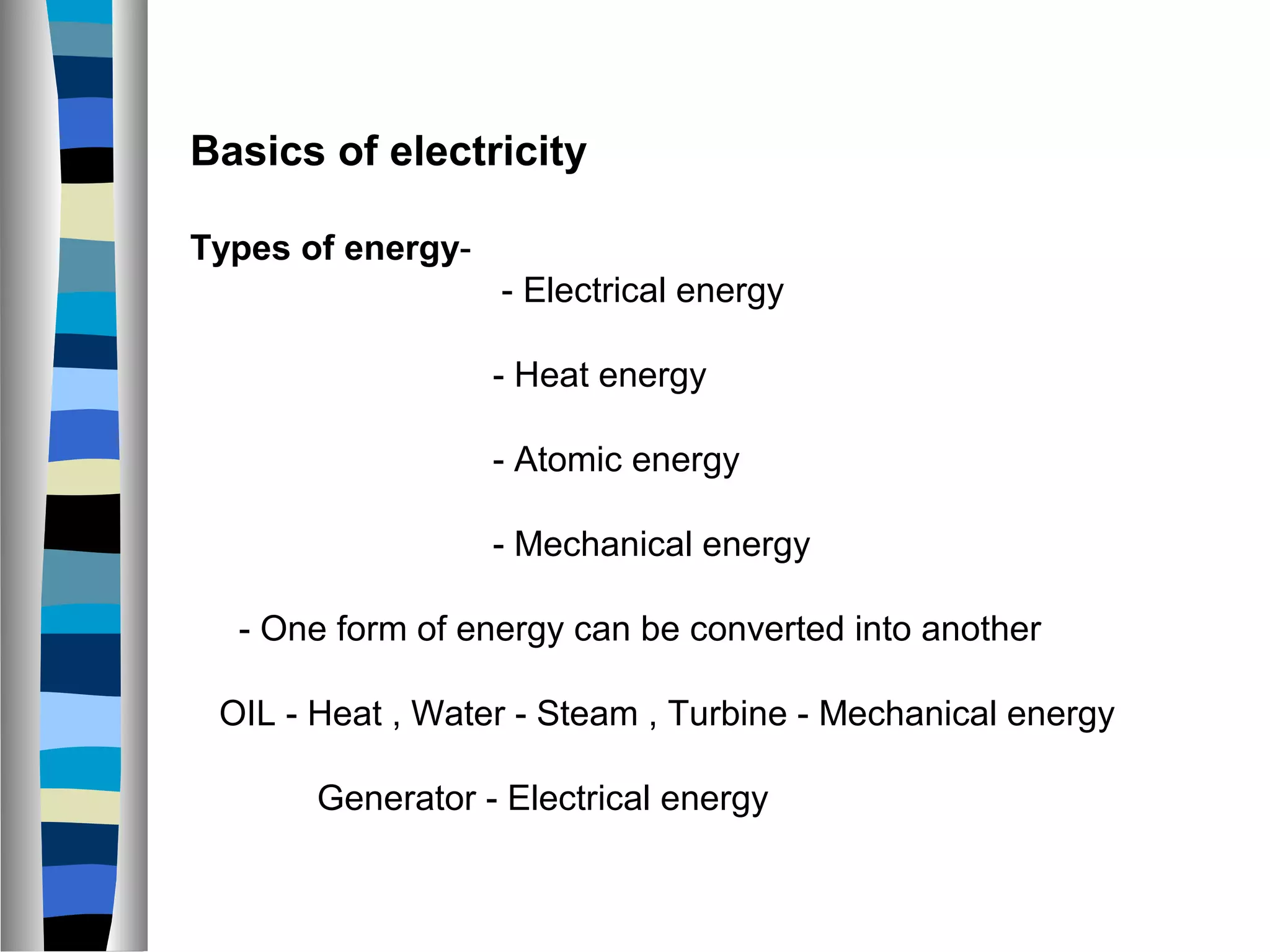
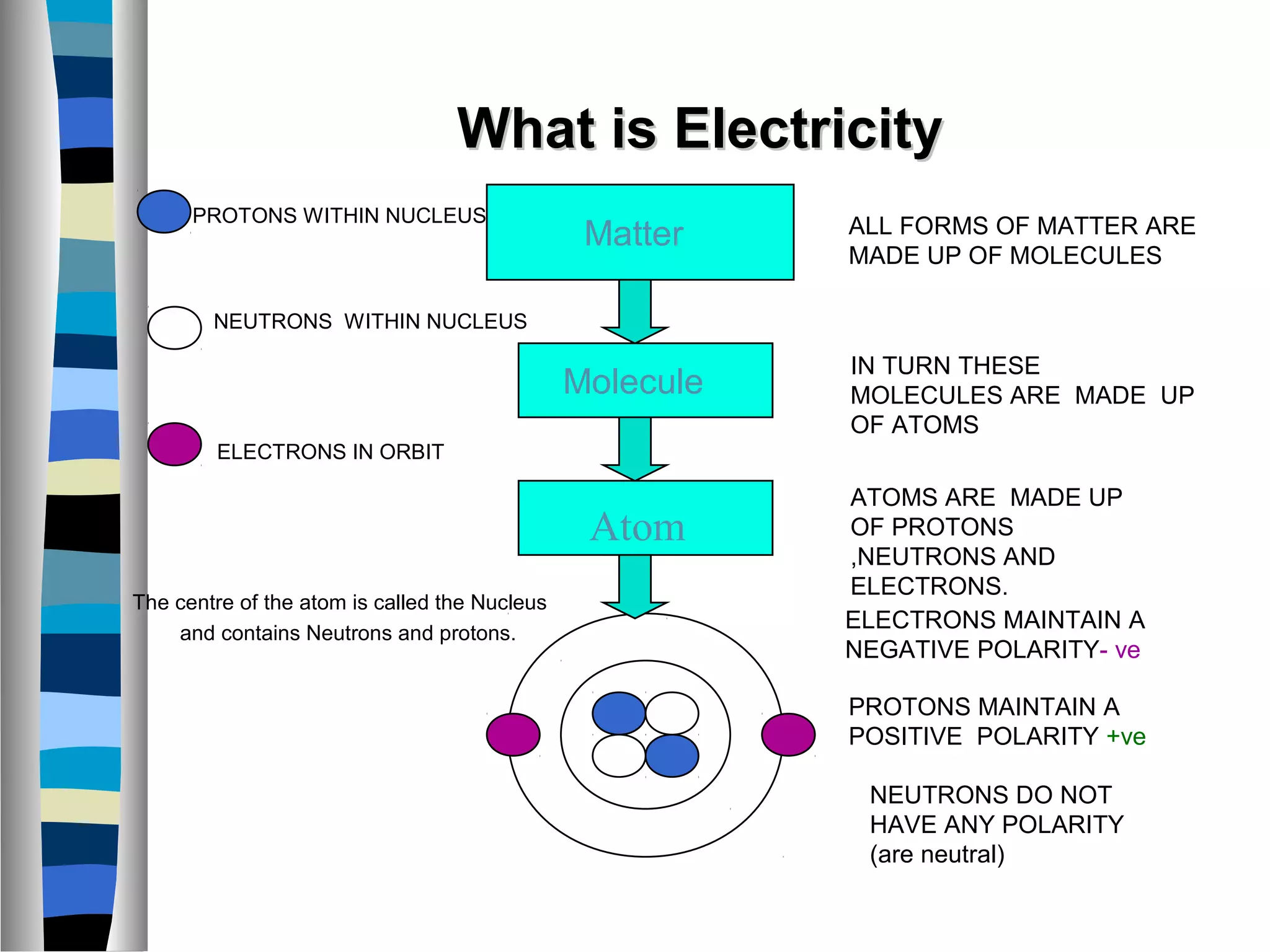
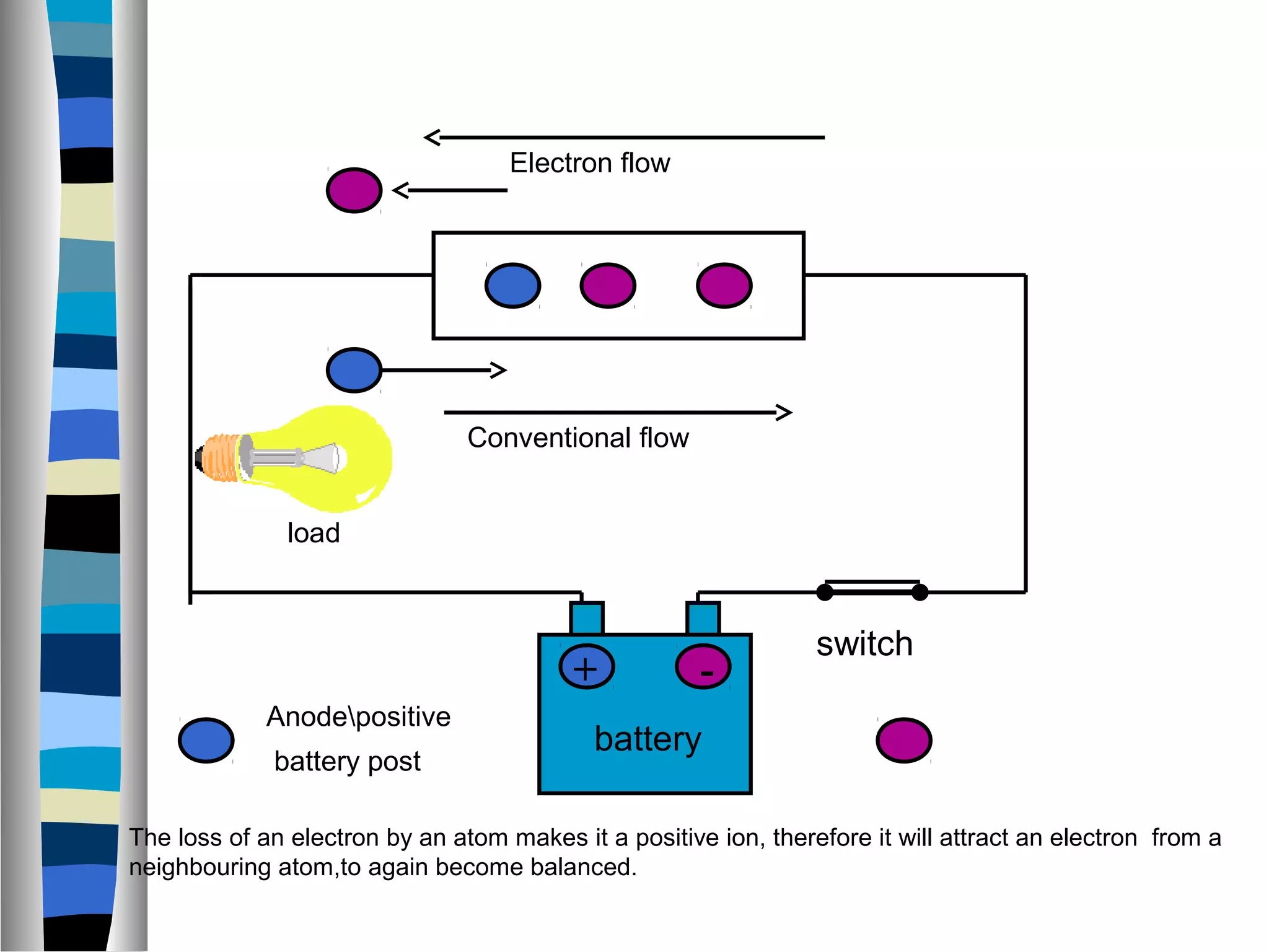
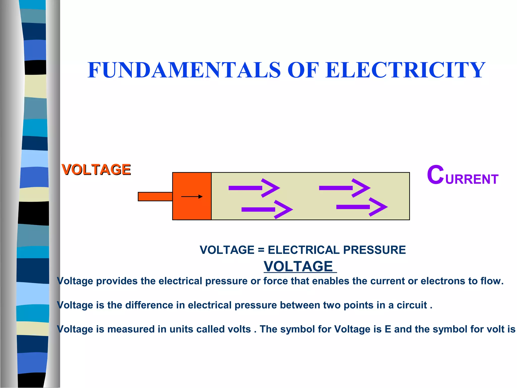
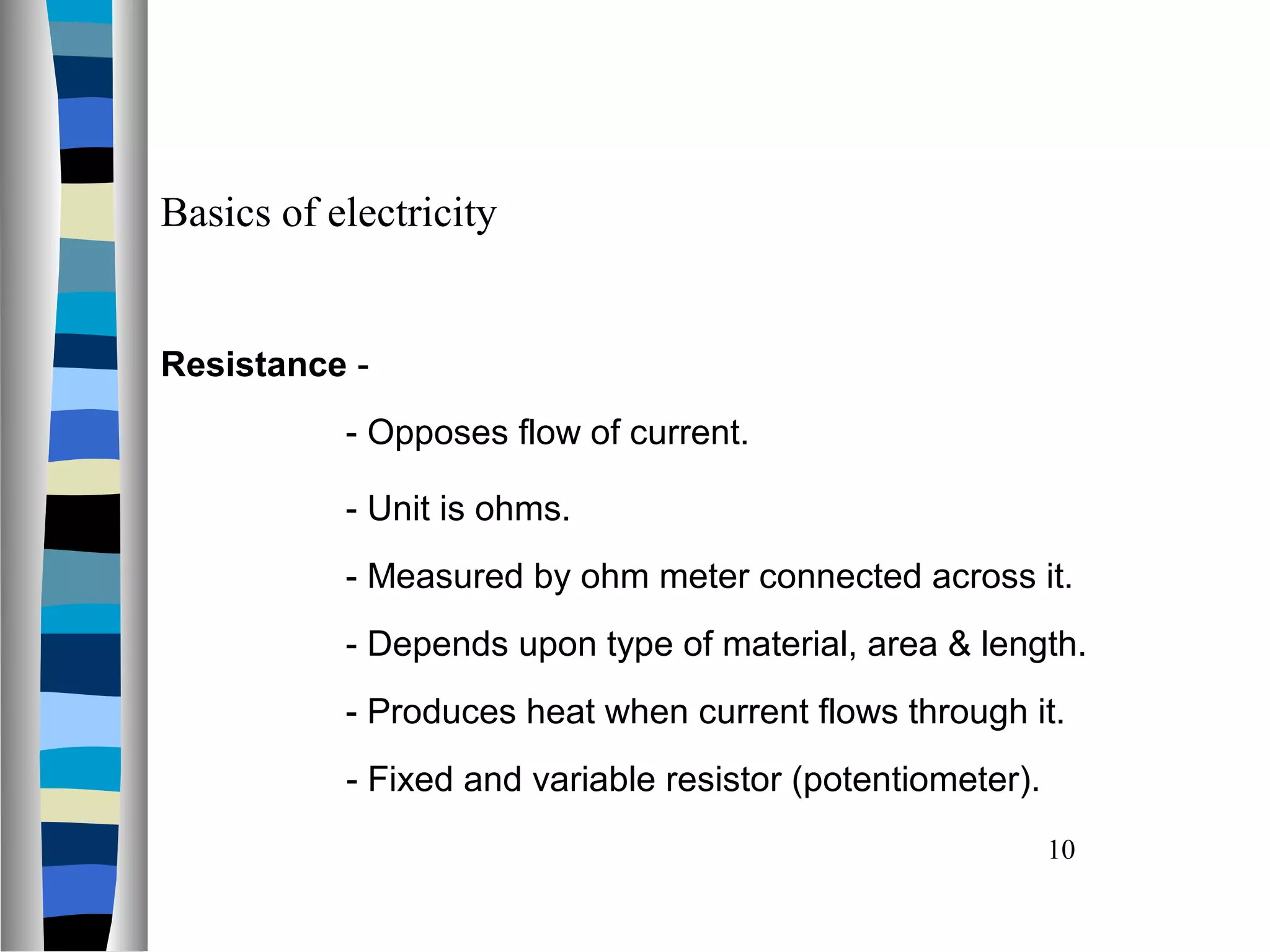
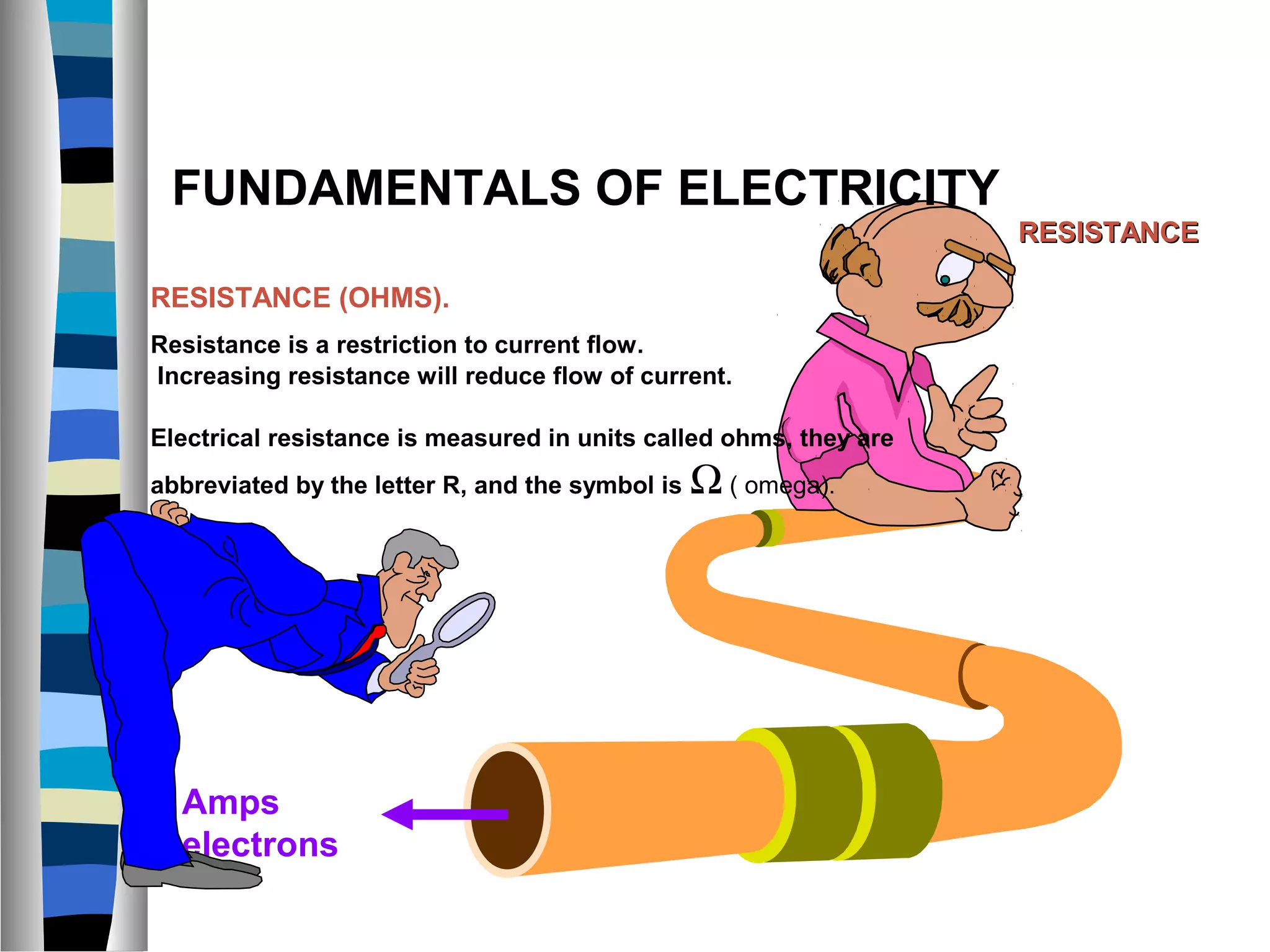
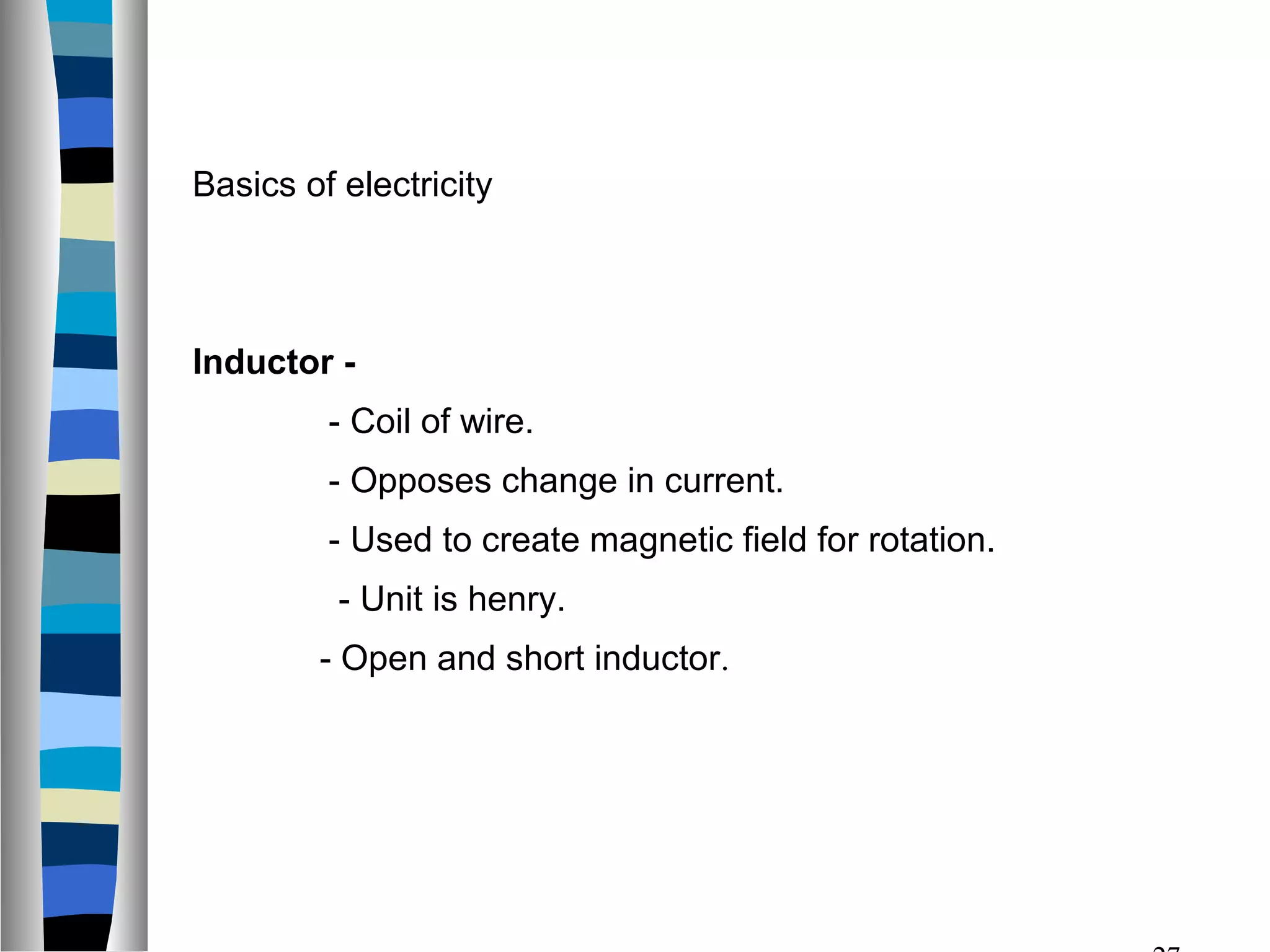
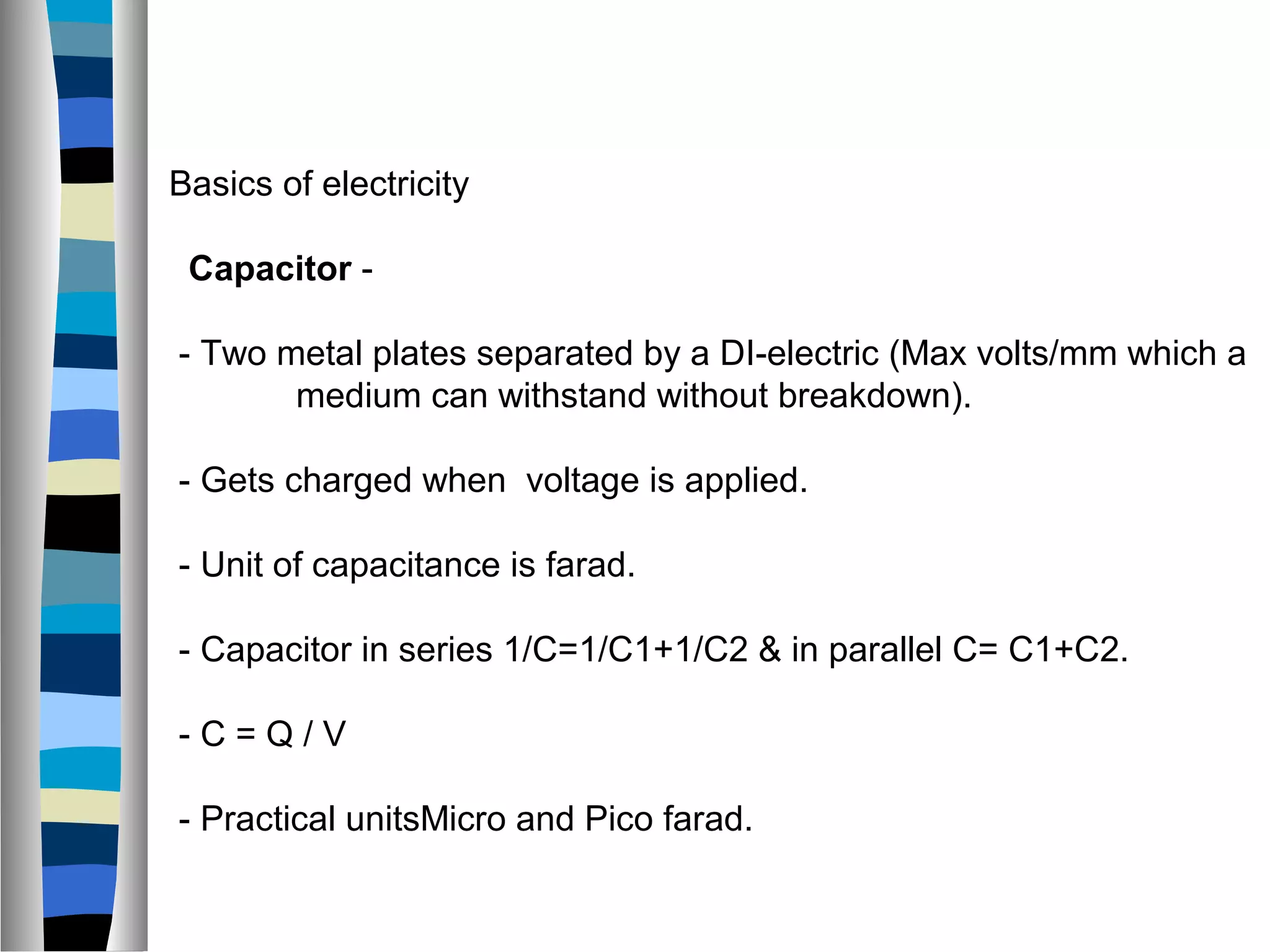
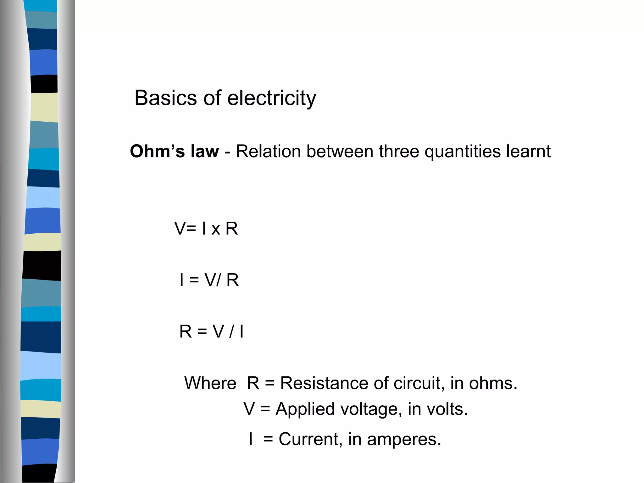
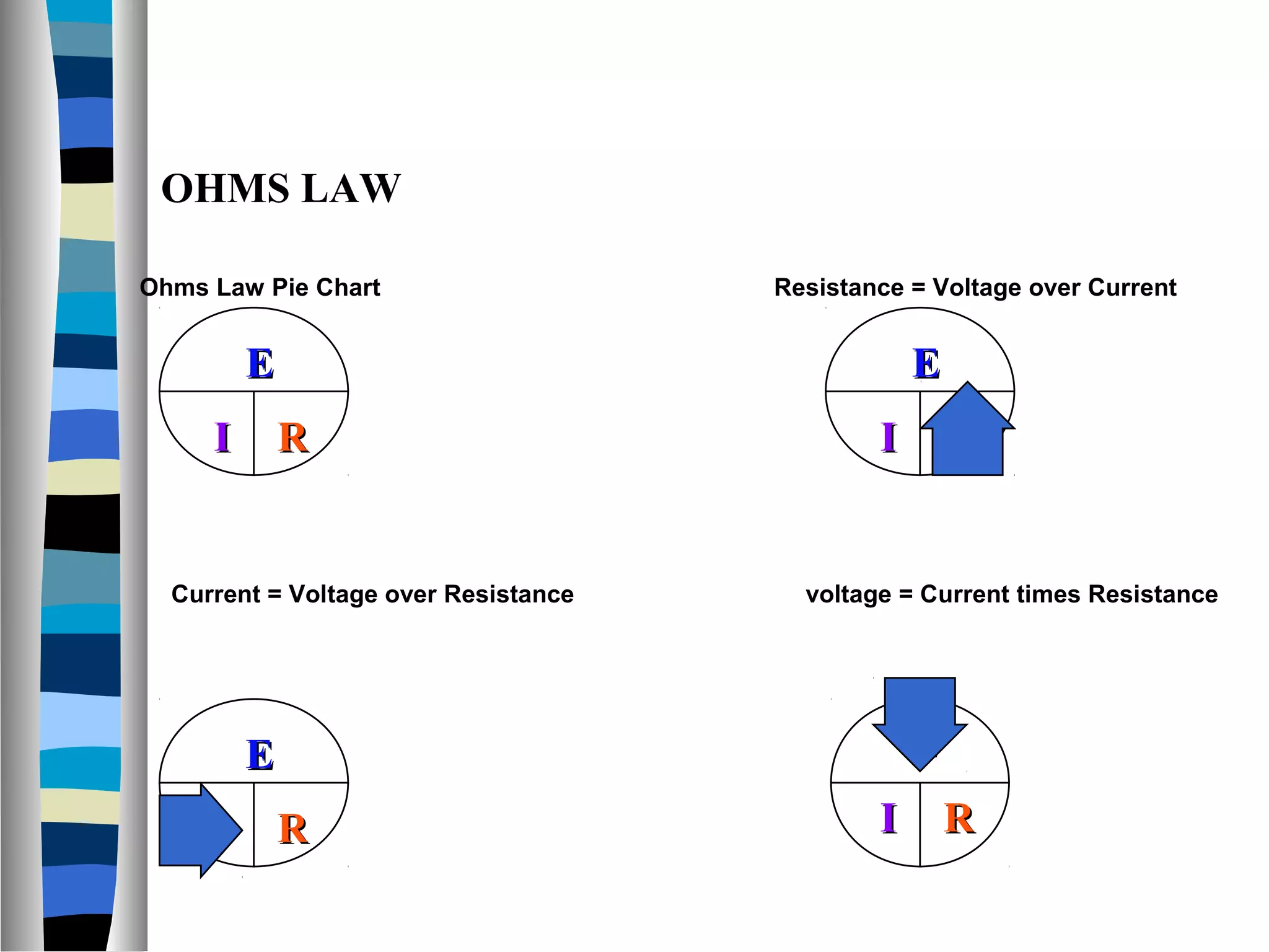
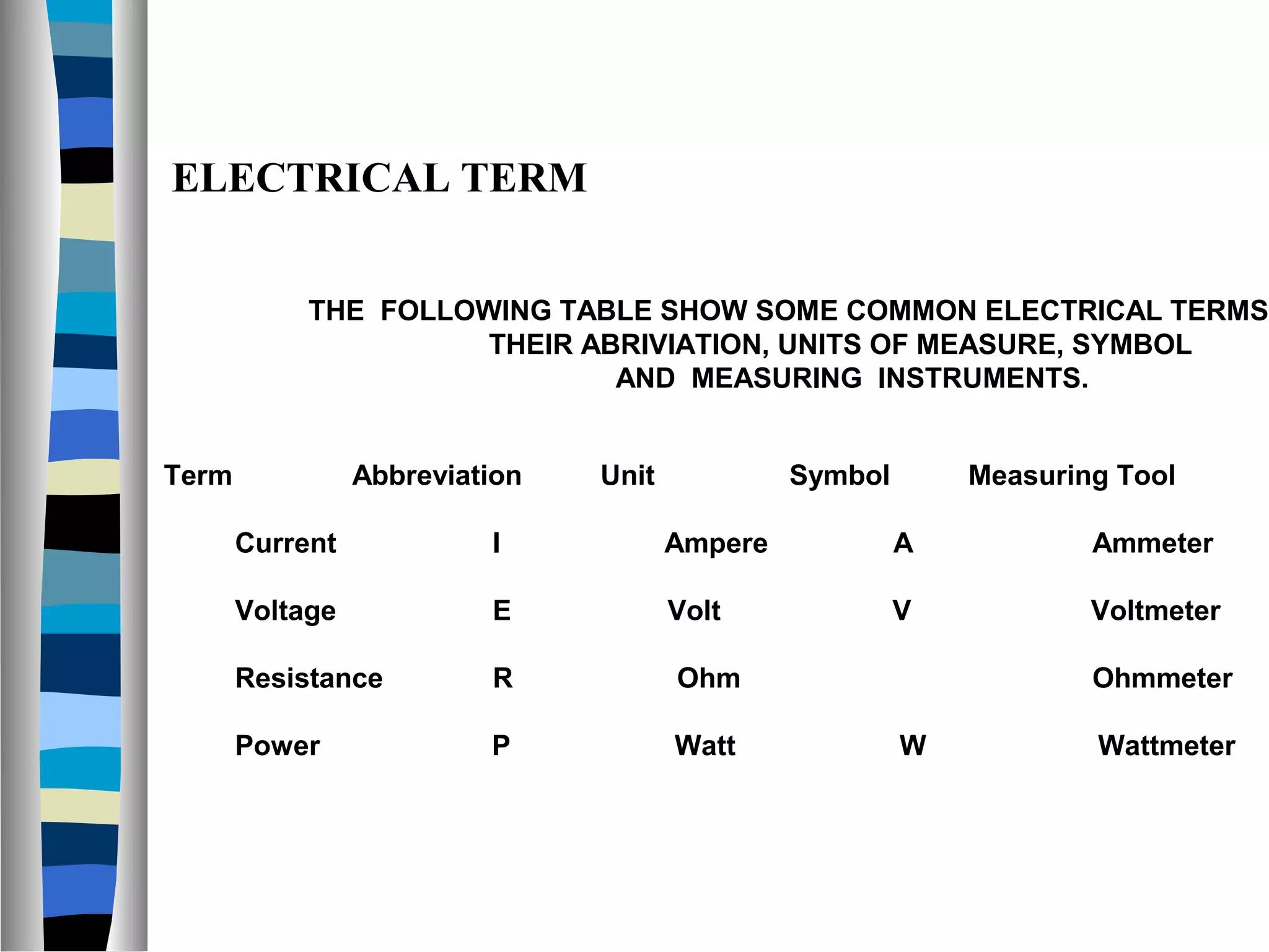
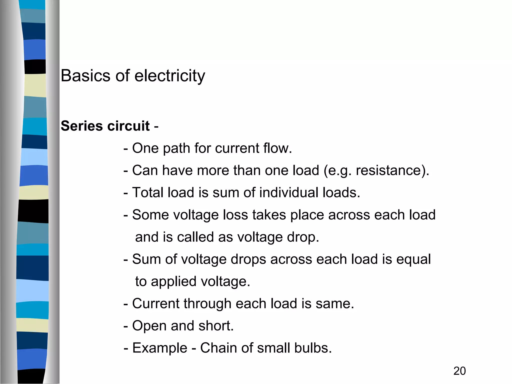
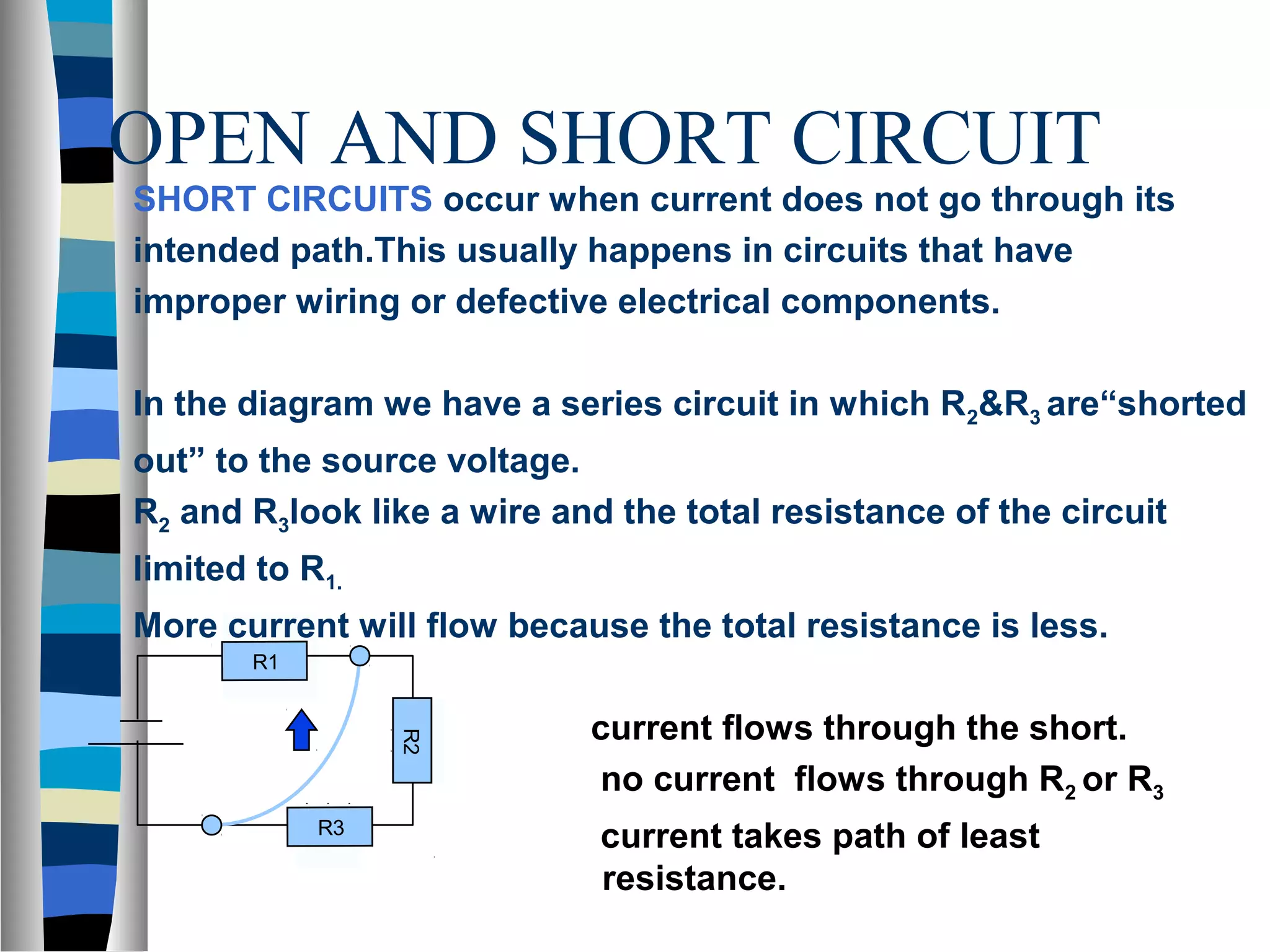
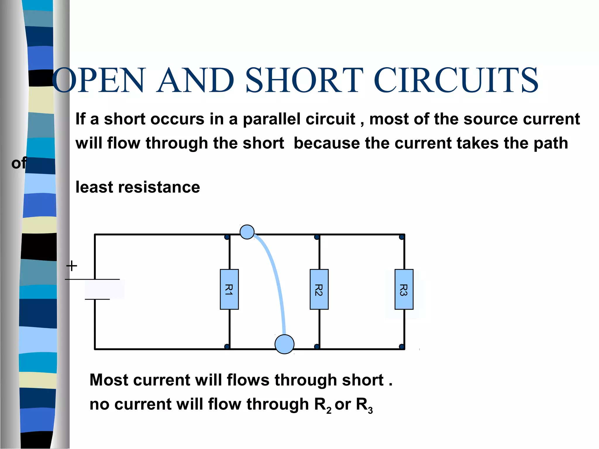
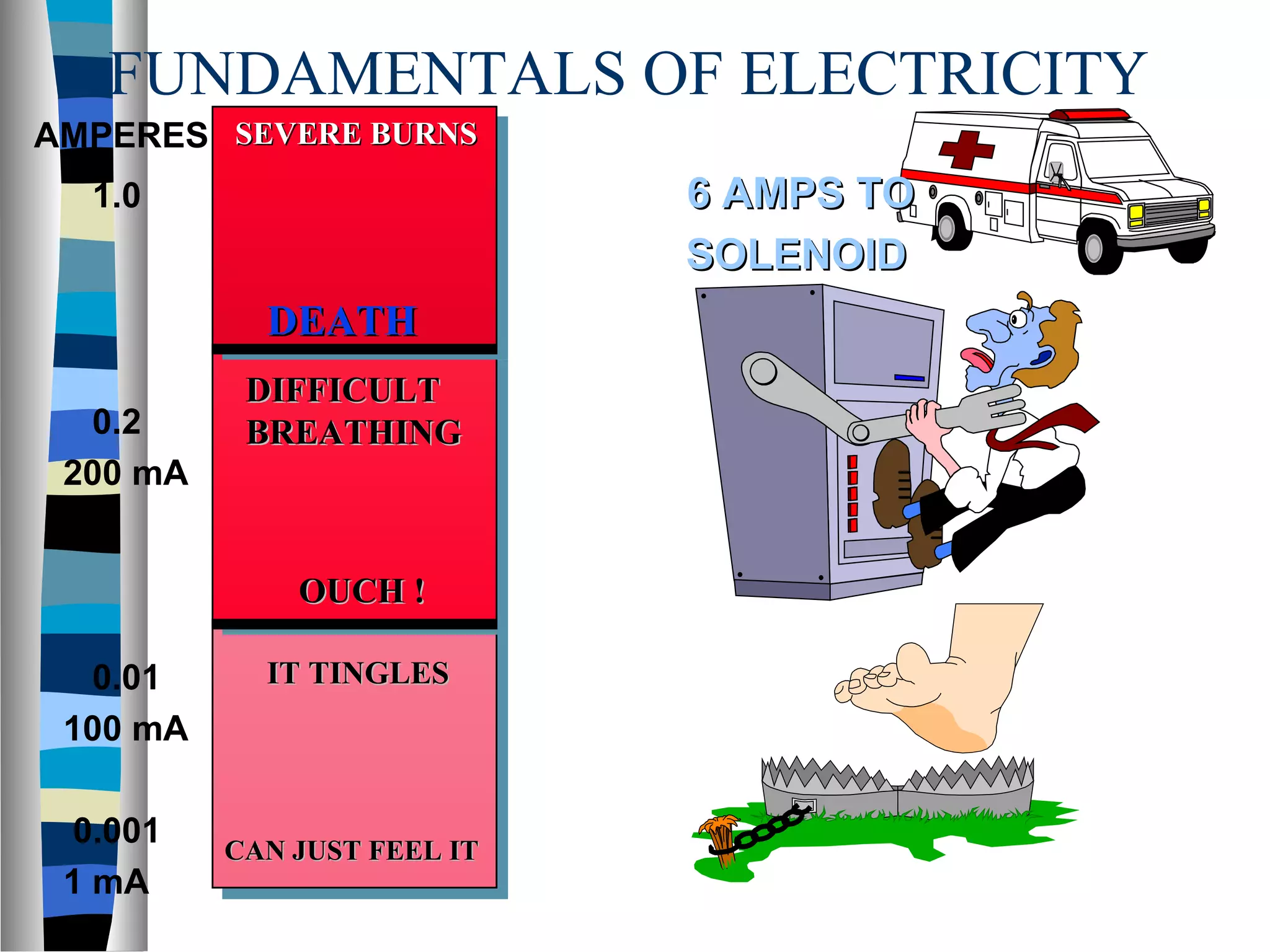
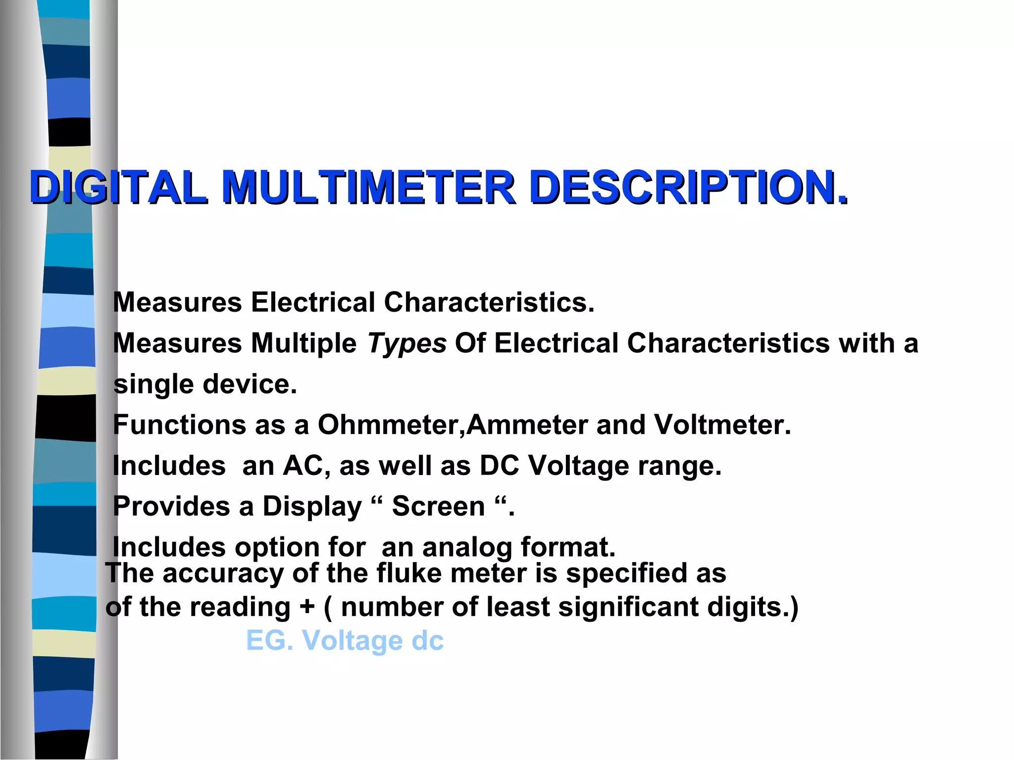
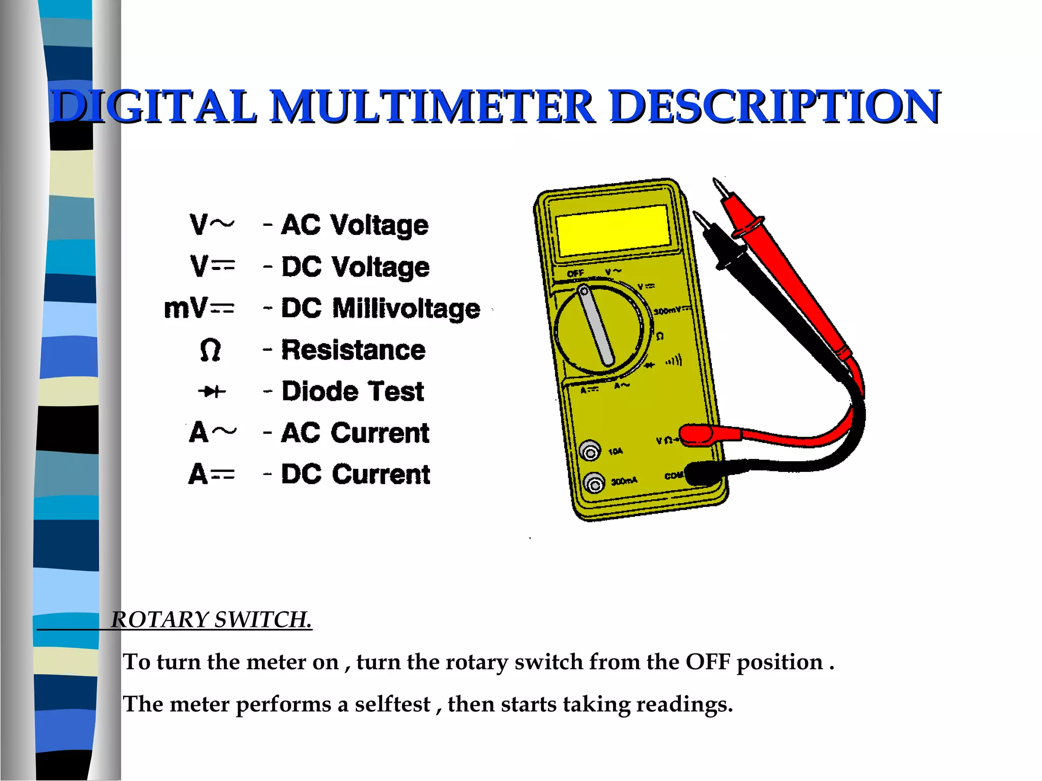
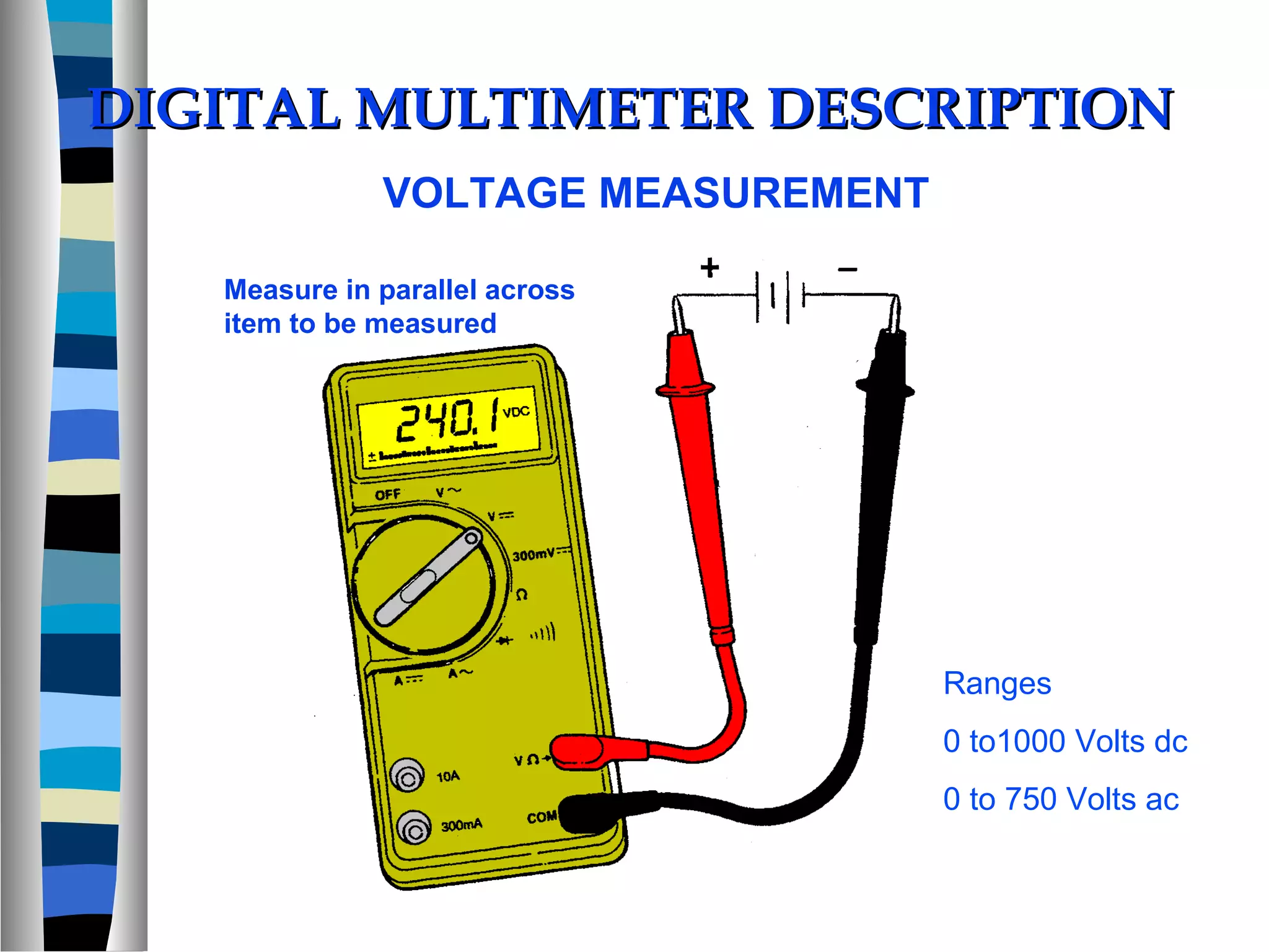
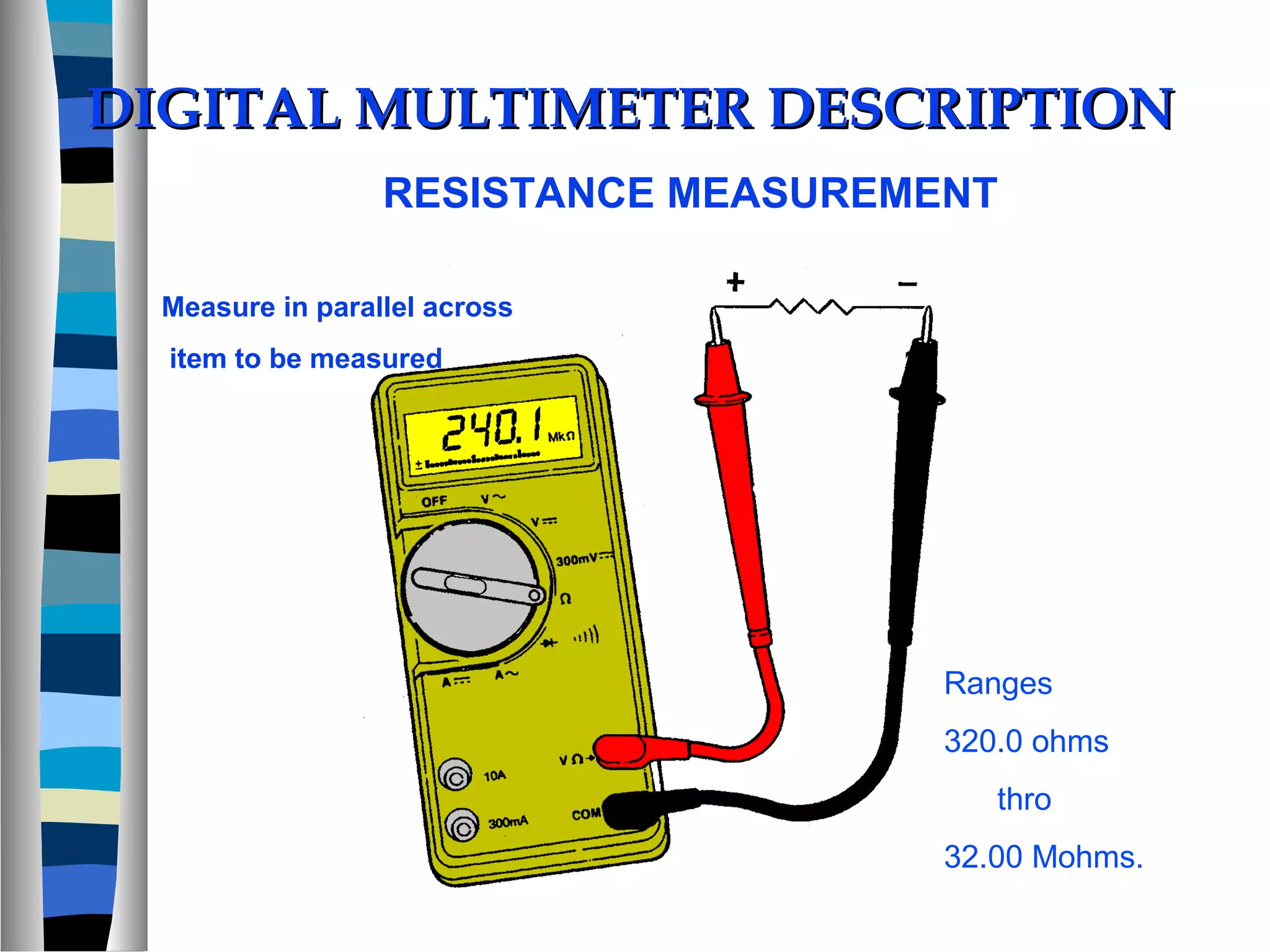
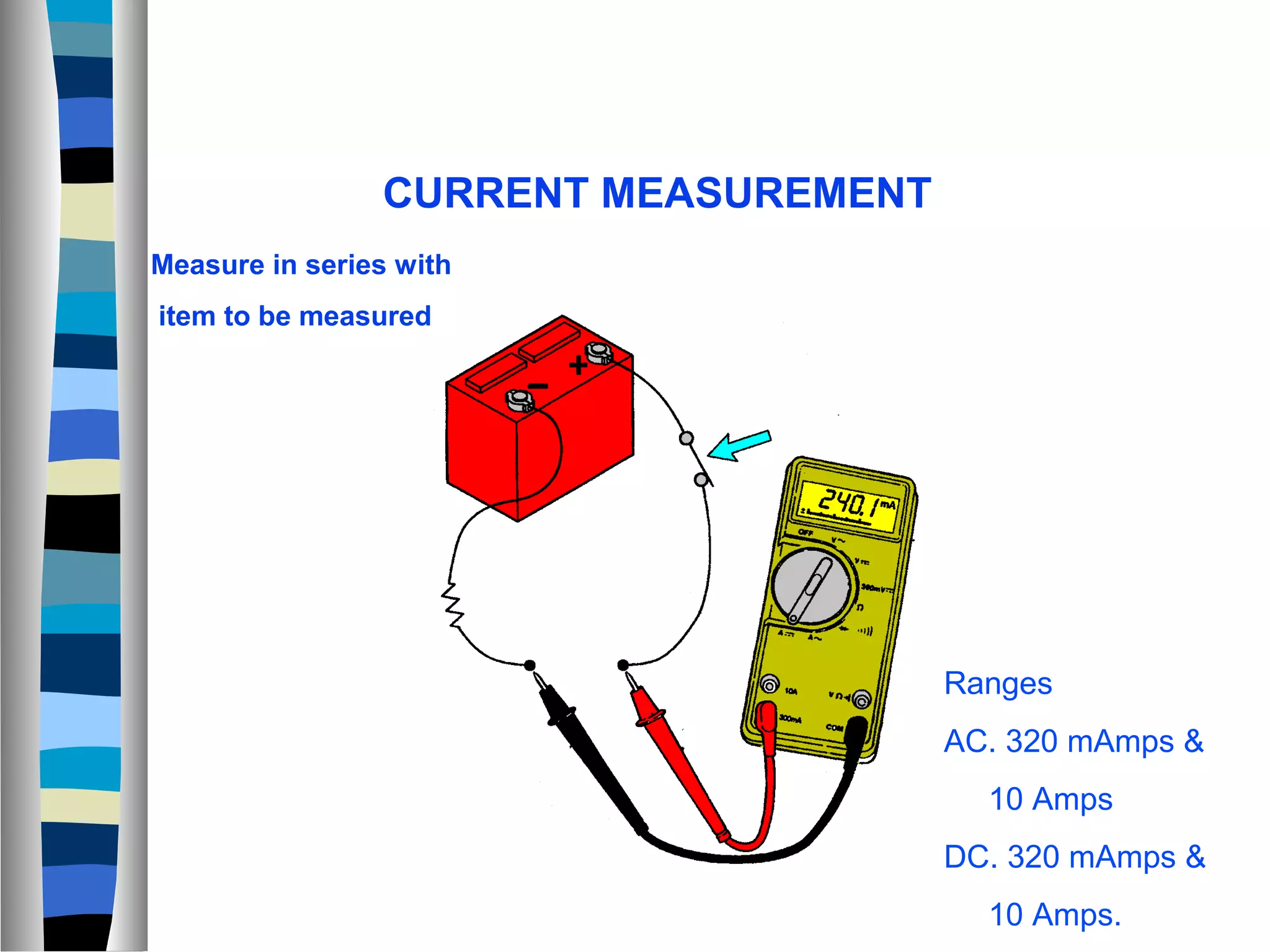

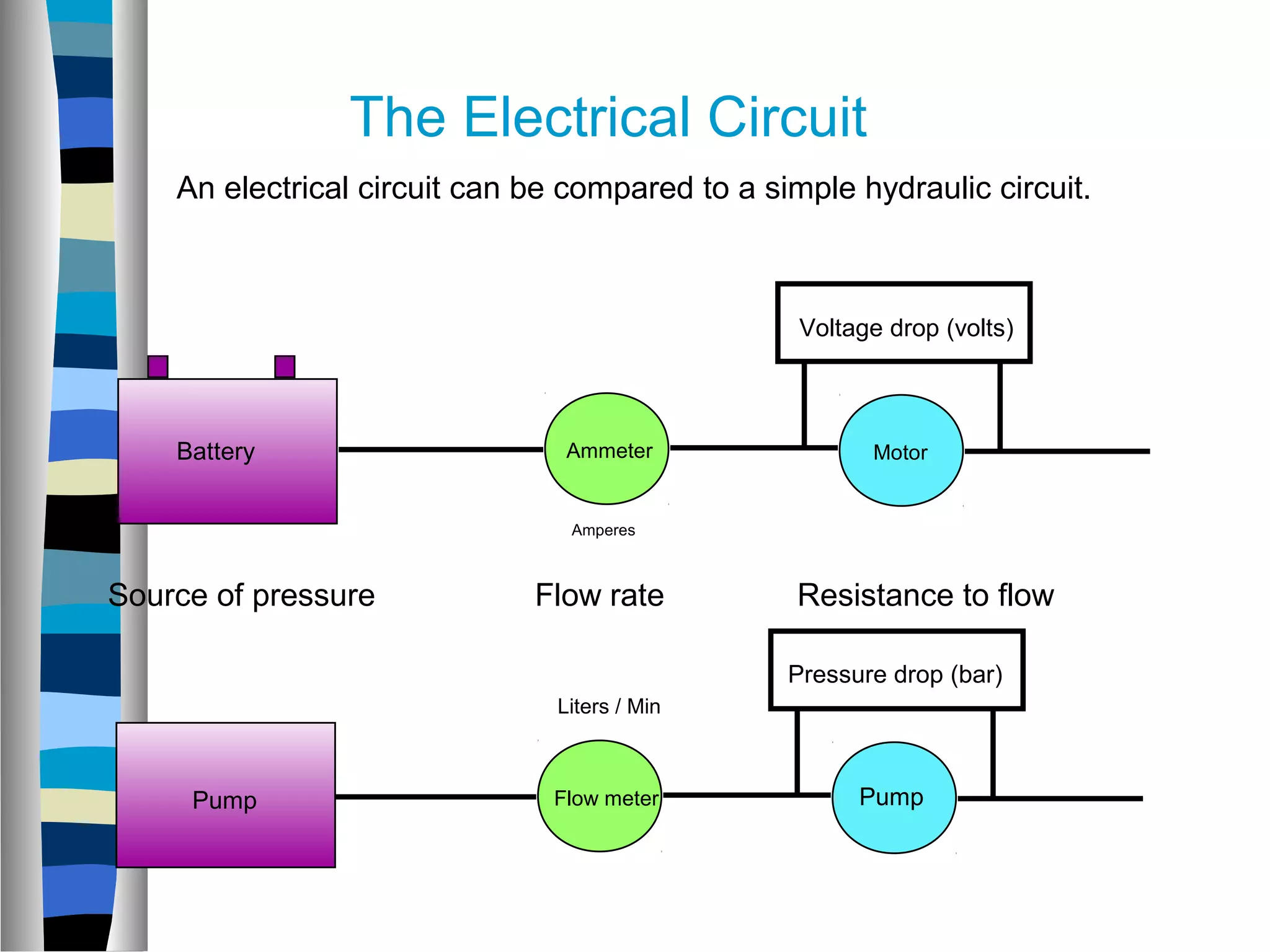
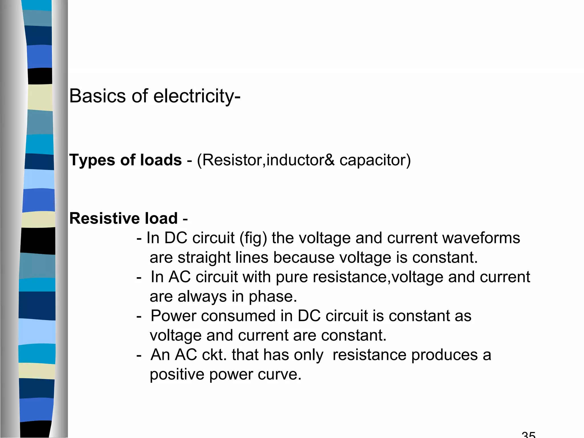

This document provides an introduction and overview of basic electricity concepts. It begins by outlining the objectives of electricity training which are to understand Ohm's law, electrical terms, and the relationship between voltage, current and resistance. It then discusses the basics of electricity including different types of energy, current, voltage, resistance, and Ohm's law. The document also covers topics like series and parallel circuits, AC/DC power, and introduces the use of a digital multimeter for electrical measurements.


