This document provides information about the fifth edition of the textbook "Engineering Drawing & Design" by David A. Madsen and David P. Madsen. It lists the authors and their qualifications and experience in engineering drafting. It also provides basic copyright information and notices about the electronic version of the textbook. The document gives an overview of the authors and scope of the textbook without providing many details about its content.


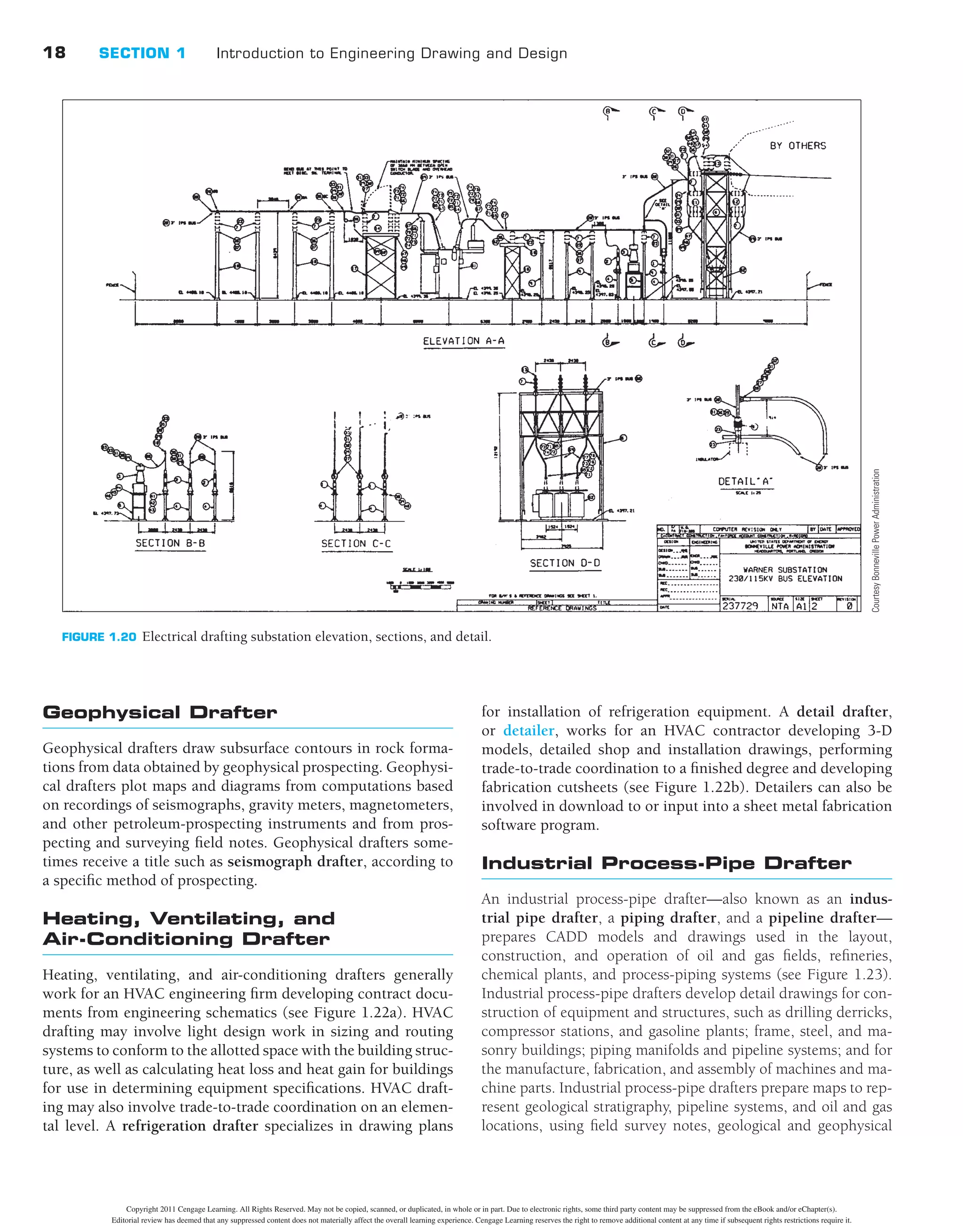


![22 SECTION 1 Introduction to Engineering Drawing and Design
and photographs by methods and techniques suited to speci-
fied reproduction process or final use, photo-offset, and pro-
jection transparencies, using drafting and optical equipment.
Technical illustrators create schematic, perspective, axono-
metric, orthographic, and oblique-angle views to depict func-
tions, relationships, and assembly sequences of parts and
assemblies such as gears, engines, and instruments. Techni-
cal illustrators also create rendered drawings and 3-D mod-
els, and they may draw cartoons and caricatures to illustrate
operation, maintenance, and safety manuals and posters (see
Figure 1.28).
Tool-and-Die Design Drafter
Tool-and-die design drafting is a specialization of mechanical
drafting. Tool-and-die design drafters prepare CADD models
and detailed drawing plans for manufacturing tools, usually fol-
lowing designs and specifications indicated by tool designers.
.300
1.740
2.300
4X .75
2X .250-20 UNC-2B
SHOWN
PROJECT:
DRAWN
CHECK
DESIGN
ENGR
APPR
DATE
TITLE
SIZE CAGE DWG. NO.
SCALE PRINTED:
REVISIONS
DESCRIPTION
ZONE LTR DATE APPROVED
REV
DWG NO.
Portland Or 97224
16505 SW 72nd Ave
FLIR Systems Inc.
CALC. WT.
FINISH
MATERIAL
DECIMALS .XX
.XXX
HOLE Ø .XX
.XXX
ANGLES 0°30'
BENDS ±2°
FRACTIONS ± 1/32 STRAIGHTNESS &/OR
FLATNESS: .005/IN
THREADS:
EXTERNAL-CLASS 2A
INTERNAL-CLASS 2B
ANGLES,BENDS,&
INTERSECTIONS:90°
MACHINED SURFACES:
SAMPLES MUST BE APPROVED BY ENG.
PRIOR TO STARTING PRODUCTION
63 OR BETTER
7
A
8 6 5 4 3 2 1
B
C
D
A
B
C
D
8 7 6 5 4 3 1
REV
SHEET OF
D 64869
+
-
UNLESS OTHERWISE SPECIFIED
DIMENSIONS ARE IN INCHES ALL
DIMENSIONS IN [ ] ARE MM DO NOT
SCALE DRAWING
PERPEND. .003/IN
CONCEN. .003/IN
03-001864 0
SADDLE - TELESCOPE
LENS MTG
AL, 6061-T6
CHEM FILM PER
PER QQ-A-250/11
±.005
.003
.001
±.015
±.005
MIL-C-5541, CL 3
1
1
1/1
0
4X 30°
6.20
R2.100
35°
2X 113°
1.700
.120
.400
2X R1.950
R1.852 ±.001
VIEW A-A
3.10
2X 1.23
(3.58)
R1.805
15°
30°
2X 67°
1.70
.500
6X .138-32 UNC-2B
.25 MIN
A
2X .250-20 UNC-2B
.30 MIN
.10
R.25
2.100 .95
.50
2.100
30°
2X 67°
2X .40
2.350
.030
.060
5.400
.44 MIN
2X 113°
2.700
R2.350
2X .125
2.350
4X Ø.270 ±.010 THRU
Ø.44 .43
4
.420
2.000
2X 60°
4X R3.000
.60
2X 1.250
1.70
1.25
.12 X 45°
4
5X .280
SHOWN
SHOWN
Ø.28
Ø.44
5X Ø.180 THRU
Ø.312 .25
NOTES:
1. INTERPRET DRAWING IAW MIL-STD-100.
2. DIMENSIONS AND TOLERANCES PER ASME Y14.5-2009.
3. PART TO BE FREE OF BURRS AND SHARP EDGES.
4. IDENTIFY IAW MIL-STD-130, BY RUBBER STAMP OR HAND MARK, CONTRASTING
COLOR, .12 HIGH GOTHIC STYLE CHARACTERS, INCLUDE LATEST REV LEVEL:
64869-XXXXXXXX REV_. LOCATE APPROX AS SHOWN.
A
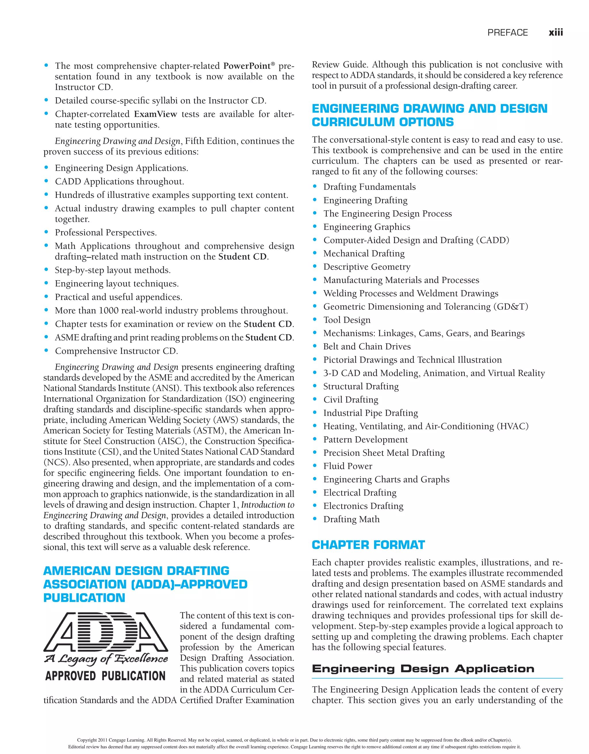
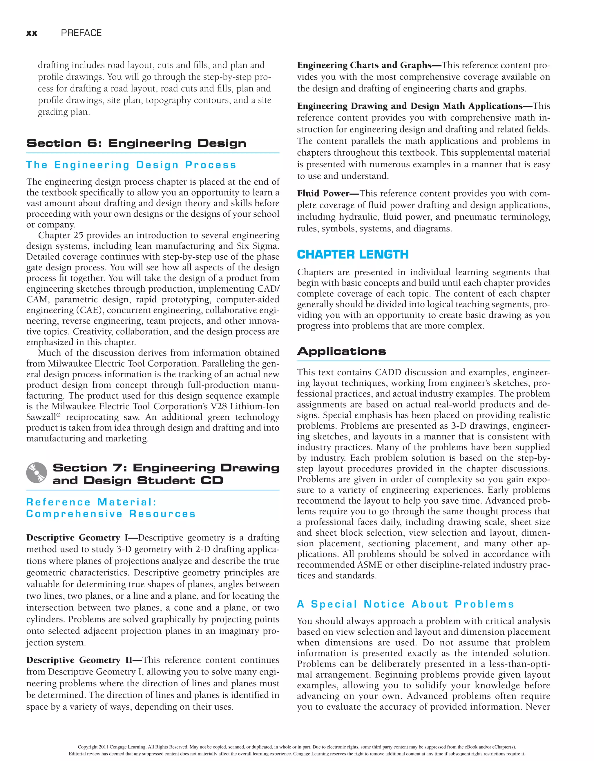
FIGURE 1.25 A mechanical drawing of a part for a thermal camera assembly. Courtesy FLIR Systems, Inc.
EDUCATION AND QUALIFICATIONS
The design and drafting profession can provide a rewarding
career for people who enjoy detailed work and have a mechan-
ical aptitude and ability to visualize. Math and communication
skills are also important. The following information describes
education and qualification requirements for an entry-level
drafting position. The information is taken partly from the
Occupational Outlook Handbook published by the U.S. Depart-
ment of Labor, Bureau of Labor Statistics (www.bls.gov/oco).
High school courses in mathematics, science, computer tech-
nology, design, computer graphics, and drafting are useful for
people considering a drafting career. However, employers in
the drafting industry prefer applicants who have at least two
years of postsecondary training in a drafting program that pro-
vides strong technical skills and considerable experience with
CADD systems. Employers are most interested in applicants
with a strong background in fundamental drafting principles;
Copyright 2011 Cengage Learning. All Rights Reserved. May not be copied, scanned, or duplicated, in whole or in part. Due to electronic rights, some third party content may be suppressed from the eBook and/or eChapter(s).
Editorial review has deemed that any suppressed content does not materially affect the overall learning experience. Cengage Learning reserves the right to remove additional content at any time if subsequent rights restrictions require it.](https://image.slidesharecdn.com/davidp-230925180757-12bdde0f/75/David-P-Madsen-David-A-Madsen-Engineering-Drawing-and-design-pdf-52-2048.jpg)


![122 SECTION 1 Introduction to Engineering Drawing and Design
that retains its strength under high temperatures. Because of their
great heat resistance, refractories are used for high-temperature
applications such as furnace liners. Composites are two or more
materials that are bonded together by adhesion, a force that
holds together the molecules of unlike substances when the sur-
faces come in contact. These materials generally require carbide
cutting tools or special methods for machining.
Ferrous Metals
The two main types of ferrous metals are cast iron and steel.
These metals contain iron. There are many classes of cast iron
and steel that are created for specific types of application based
on their composition.
Cast Iron
There are several classes of cast iron, including gray, white,
chilled, alloy, malleable, and nodular. Cast iron is primarily an
alloy of iron and 1.7% to 4.5% of carbon, with varying amounts
of silicon, manganese, phosphorus, and sulfur.
G r a y C a s t I r o n
Gray iron is a popular casting material for automotive cylinder
blocks, machine tools, agricultural implements, and cast iron
pipe. Gray cast iron is easily cast and machined. It contains
1.7% to 4.5% carbon and 1% to 3% silicon.
INTRODUCTION
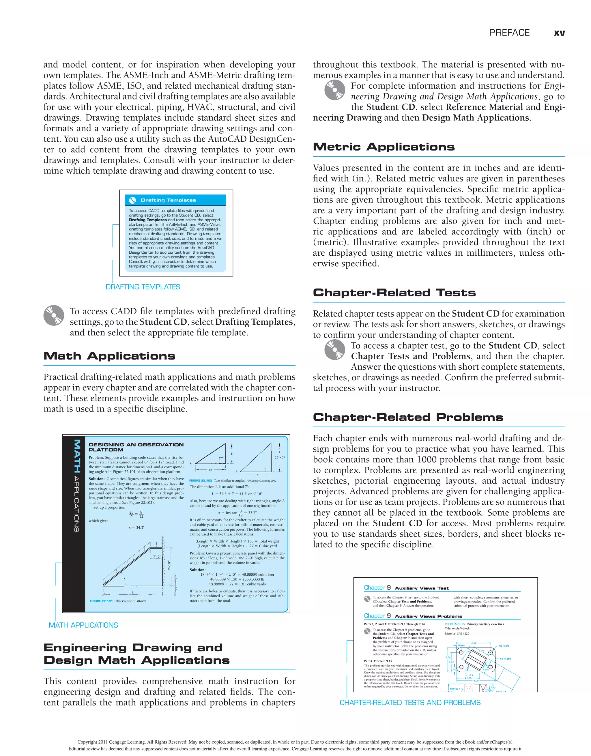
A number of factors influence product manufacturing. Begin-
ning with research and development (R&D), a product should
be designed to meet a market demand, have good quality, and
be economically produced. R&D is the first phase used to deter-
mine the feasibility of new products or the evolution of existing
products using creativity, market research, product research,
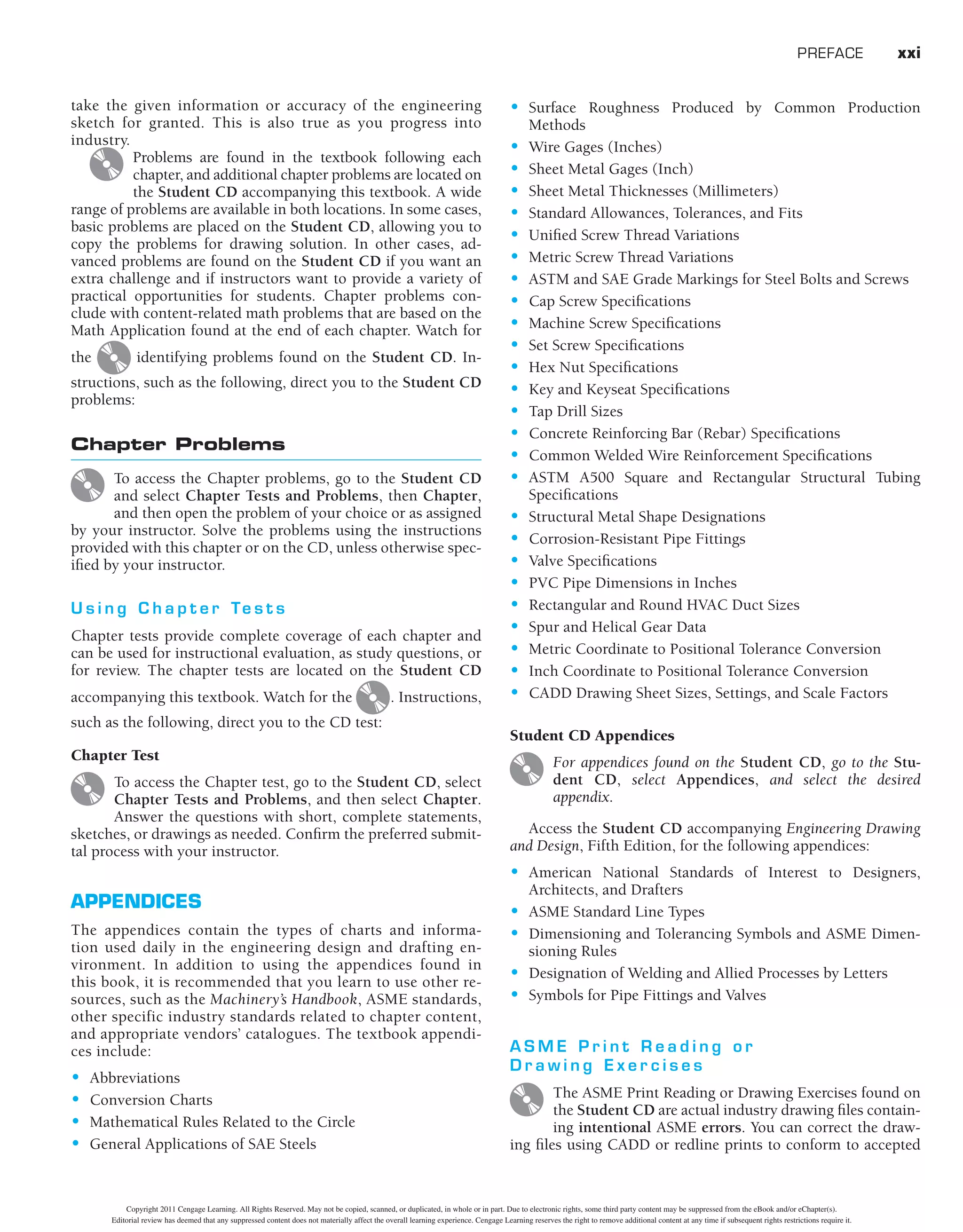
and prototype development. The sequence of product develop-
ment begins with an idea and results in a marketable commod-
ity as shown in Figure 4.2.
MANUFACTURING MATERIALS
A wide variety of materials available for product manufacturing
fall into three general categories: metal, plastic, and inorganic
materials. Metals are classified as ferrous, nonferrous, and alloys.
Ferrous metals contain iron in some form such as cast iron and
steel. Nonferrous metals do not have iron content; for example,
copper and aluminum. Alloys are mixtures of two or more metals.
Plastics or polymers have two types of structure: thermoplastic
and thermoset. Thermoplastic material can be heated and formed
by pressure and the shape can be changed on reheating. Thermoset
plastics are formed into a permanent shape by heat and pressure
and cannot be altered by heating after curing. Plastics are molded
into shape and only require machining for tight tolerance situa-
tions or when holes or other features are required, features that
would be impractical to produce in a mold. It is common practice
to machine some plastics for parts, such as gears and pinions.
Inorganic materials include carbon, ceramics, and compos-
ites. Carbon and graphite are classified together and have prop-
erties that allow molding by pressure. These materials have low
tensile strength (the ability to be stretched) and high compres-
sive strength, with increasing strength at increased tempera-
tures. Ceramics are clay, glass, refractory, and inorganic cements.
Ceramics are very hard, brittle materials that are resistant to heat,
chemicals, and corrosion. Clay and glass materials have an amor-
phous structure, whereas refractories must be bonded together
by applying temperatures. A refractory is a nonmetallic material
RESEARCH
AND
DEVELOPMENT
PROTOTYPE
DRAWINGS
DISTRIBUTION
AND
SALES
PROTOTYPE
CONSTRUCTION
OR
MODELING
ASSEMBLY
ENGINEERING
DRAWINGS
AND
DOCUMENTS
MANUFACTURING
PROCESSES
FIGURE 4.2 Sequence of product development. © Cengage Learning 2012
ASTM The American Society for Testing Materials
(ASTM) specifications A48–76 group gray cast iron into
two classes: (1) easy to manufacture (20A, 20B, 20C,
25A, 25B, 25C, 30A, 30B, 30C, 35A, 35B, 35C) and (2)
more difficult to manufacture (40B, 40C, 45B, 45C, 50B,
50C, 60B, 60C). The prefix number denotes the mini-
mum tensile strength in thousand of pounds per square
inch. For more information or to order standards, go to
the ASTM Web site at www.astm.org.
STANDARDS
W h i t e C a s t I r o n
White cast iron is extremely hard and brittle, and it has almost no
ductility. Ductility is the ability to be stretched, drawn, or ham-
mered thin without breaking. Caution should be exercised when
using this material because thin sections and sharp corners may
be weak, and the material is less resistant to impact uses. This cast
ironissuitedforproductswithmorecompressivestrengthrequire-
ments than gray cast iron [compare more than 200,000 pounds
per square inch (psi) with 65,000 to 160,000 psi]. White cast iron
is used where high wear resistance is required.
C h i l l e d C a s t I r o n
An outer surface of white cast iron results when gray iron cast-
ings are chilled rapidly. This chilled cast iron material has the
internal characteristics of gray cast iron and the surface advan-
tage of white cast iron.
Copyright 2011 Cengage Learning. All Rights Reserved. May not be copied, scanned, or duplicated, in whole or in part. Due to electronic rights, some third party content may be suppressed from the eBook and/or eChapter(s).
Editorial review has deemed that any suppressed content does not materially affect the overall learning experience. Cengage Learning reserves the right to remove additional content at any time if subsequent rights restrictions require it.](https://image.slidesharecdn.com/davidp-230925180757-12bdde0f/75/David-P-Madsen-David-A-Madsen-Engineering-Drawing-and-design-pdf-152-2048.jpg)


![OBJECT
LINES
SECTION
LINES
DIMENSION
LINES
EXTENSION
LINES
HIDDEN
LINES
LEADER
CENTERLINES
PHANTOM
LINE
CUTTING-PLANE
LINE
PROJECT:
DRAWN
CHECK
DESIGN
ENGR
APPR
DATE
TITLE
SIZE
CAGE
DWG.
NO.
SCALE
PRINTED:
REVISIONS
DESCRIPTION
ZONE
LTR
DATE
APPROVED
REV
DWG
NO.
Portland
Or
97224
16505
SW
72nd
Ave
FLIR
Systems
Inc.
CALC.
WT.
FINISH
MATERIAL
DIMENSIONS
ARE
IN
INCHES
UNLESS
OTHERWISE
SPECIFIED
DECIMALS
.XX
.XXX
HOLE
ÿ
.XX
.XXX
ANGLES
0º30'
BENDS
±
2º
PERPEND.
.003/IN
CONCEN
.003/IN
FRACTIONS
±
1/32
STRAIGHTNESS
&/OR
FLATNESS:
.005/IN
THREADS:
EXTERNAL-CLASS
2A
INTERNAL-CLASS
2B
ANGLES,BENDS,
&
INTERSECTIONS:
90º
MACHINED
SURFACES:
SAMPLES
MUST
BE
APPROVED
BY
ENG.
PRIOR
TO
STARTING
PRODUCTION
DO
NOT
SCALE
DRAWING
63
OR
BETTER
ALL
DIMENSIONS
IN
[
]
ARE
MM
7
A
8
6
5
4
3
2
1
B
C
D
A
B
C
D
8
7
6
5
4
3
1
REV
SHEET
OF
D
64869
+
-
SADDLE
-
TELESCOPE
LENS
MTG
AL,
6061-T6
CHEM
FILM
PER
PER
QQ-A-250/11
±
.005
.003
.001
±
.015
±
.005
MIL-C-5541,
CL
3
1
1
1/1
.300
1.740
2.300
4X
.75
2X
.250-20
UNC-2B
SHOWN
4X
30º
6.20
R2.100
35º
2X
113º
1.700
.120
.400
2X
R1.950
R1.852
±
.001
VIEW
A-A
3.10
2X
1.23
(3.58)
R1.805
15º
30º
2X
67º
NOTES:
CONTRASTING
COLOR,
.12
HIGH
GOTHIC
STYLE
CHARACTERS,
INCLUDE
IDENTIFY
IAW
MIL-STD-130,
BY
RUBBER
STAMP
OR
HAND
MARK,
PART
TO
BE
FREE
OF
BURRS
AND
SHARP
EDGES.
INTERPRET
DIMENSIONS
AND
TOLERANCES
PER
ANSI
Y14.5-2009.
LATEST
REV
LEVEL:
64869-XXXXXXXX
REV_.
LOCATE
APPROX
AS
SHOWN.
INTERPRET
DRAWING
IAW
MIL-STD-100.
3.
4
2.
1.
1.70
.500
.25
MIN
A
2X
.250-20
UNC-2B
.30
MIN
.10
R.25
2.100
.95
.50
2.100
30º
2X
67º
2X
.40
2.350
.030
.060
5.400
.44
MIN
2X
113º
2.700
R2.350
2X
.125
2.350
4X
Ø.270
±
.010
THRU
Ø.44
.43
5
.420
2.000
2X
60º
4X
R3.000
.60
2X
1.250
1.70
1.25
A
.12
X
45º
5
5X
.280
SHOWN
SHOWN
Ø.28
Ø.44
5X
Ø.180
THRU
Ø.312
.25
6X
.138-32
UNC-2B
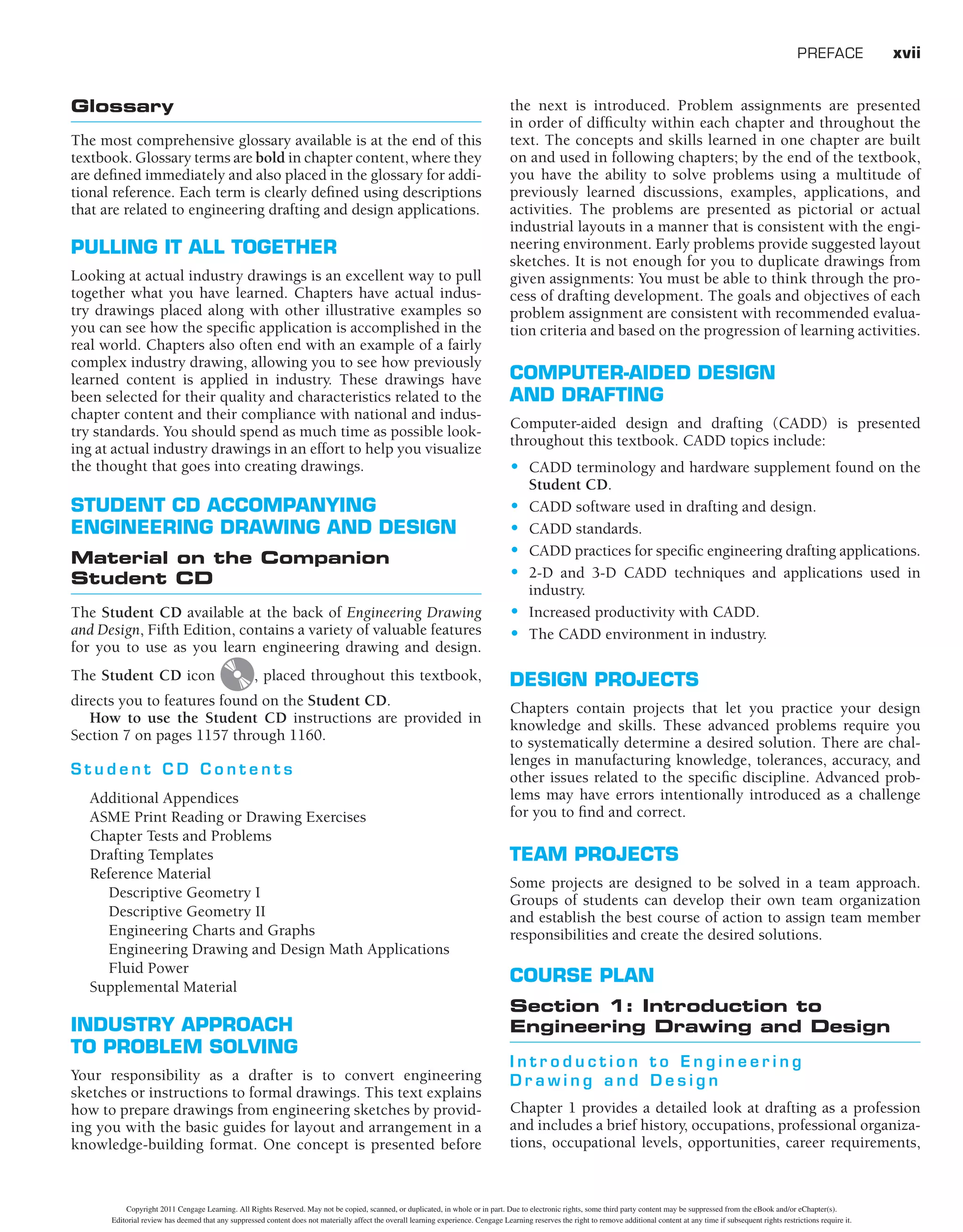
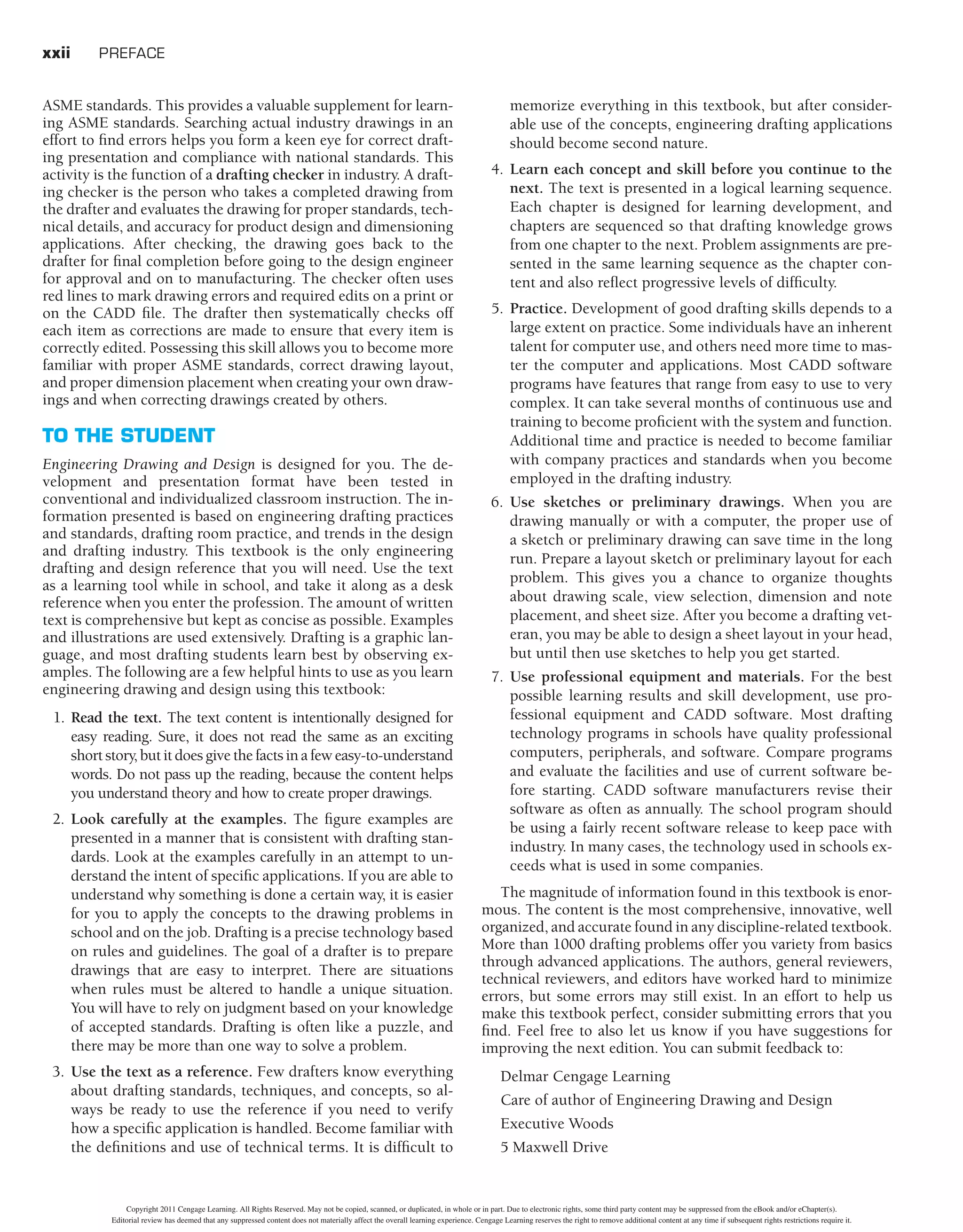
FIGURE
6.45
A
real-world
drawing
with
a
variety
of
line
types
identifi
ed.
Courtesy
FLIR
Systems,
Inc.
213
Copyright 2011 Cengage Learning. All Rights Reserved. May not be copied, scanned, or duplicated, in whole or in part. Due to electronic rights, some third party content may be suppressed from the eBook and/or eChapter(s).
Editorial review has deemed that any suppressed content does not materially affect the overall learning experience. Cengage Learning reserves the right to remove additional content at any time if subsequent rights restrictions require it.](https://image.slidesharecdn.com/davidp-230925180757-12bdde0f/75/David-P-Madsen-David-A-Madsen-Engineering-Drawing-and-design-pdf-243-2048.jpg)