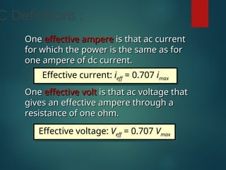
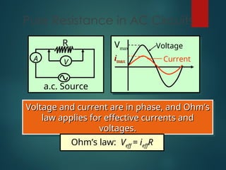
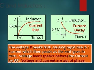
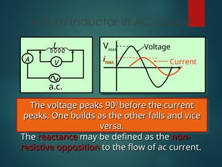
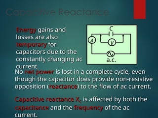
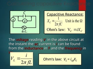
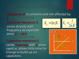
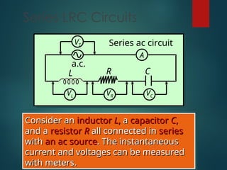
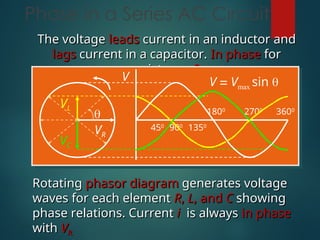
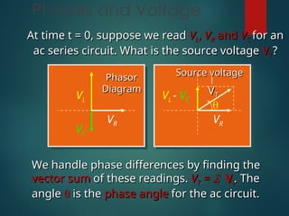
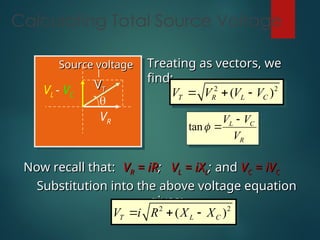
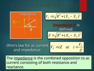
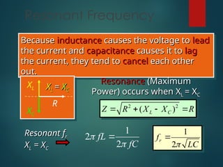
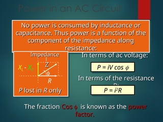
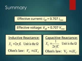
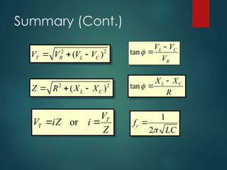
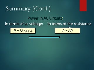
Roll No. Name
41. RATIYA RAJU
42. SATANI DARSHANA
43. SAVALIYA MILAN
44. SISARA GOVIND
45. VALGAMA HARDIK
46. VADHER DARSHAK
47. VADOLIYA MILAN
48. VALA GOPAL
49. SHINGADIYA SHYAM
50. KARUD LUKMAN
C Definitions :
One
One effective ampere
effective ampere is that ac current
is that ac current
for which the power is the same as for
one ampere of dc current.
One
One effective volt
effective volt is that ac voltage that
is that ac voltage that
gives an effective ampere through a
resistance of one ohm.
Effective current: ieff = 0.707 imax
Effective voltage: Veff = 0.707 Vmax
Pure Resistance in AC Circuits
A
a.c. Source
R
V
Voltage and current are in phase, and Ohm’s
law applies for effective currents and
voltages.
voltages.
Ohm’s law: Veff = ieffR
Vmax
i
imax
max
Voltage
Current
C and Inductors :
Time, t
I
i
Current
Current
Rise
Rise

0.63I
Inductor
The voltage
The voltage V
V peaks first, causing rapid rise in
peaks first, causing rapid rise in i
i
current which then peaks as the emf goes to
zero. Voltage
zero. Voltage leads (peaks before)
leads (peaks before) the current
the current
by 90
by 900
0
.
. Voltage and current are out of phase
Voltage and current are out of phase.
.
Time, t
I i
Current
Current
Decay
Decay

0.37I
Inductor
A Pure Inductor in AC Circuit
A
L
V
a.c.
Vmax
i
imax
max
Voltage
Current
The voltage peaks 90
The voltage peaks 900
0
before the current
before the current
peaks. One builds as the other falls and vice
versa.
versa.
The
The reactance
reactance may be defined as the
may be defined as the non-
non-
resistive
resistive opposition
opposition to the flow of ac current.
to the flow of ac current.
Inductive Reactance
A
L
V
a.c.
The
The back emf
back emf induced
induced
by a changing current
provides opposition to
current, called
current, called
inductive
inductive reactance X
reactance XL
L.
.
Such losses are
Such losses are temporary
temporary, however, since the
, however, since the
current
current changes direction
changes direction, periodically re-
, periodically re-
supplying energy so that no net power is lost in
one cycle.
one cycle.
Inductive reactance X
Inductive reactance XL
L is a function of both
is a function of both
the
the inductance
inductance and the
and the frequency
frequency of the ac
of the ac
current.
current.
Calculating Inductive Reactance
A
L
V
a.c.
Inductive Reactance:
2 Unit is the
L
X fL

 
Ohm's law: L L
V iX

The
The voltage
voltage reading
reading V
V in the above circuit at
in the above circuit at
the instant the
the instant the ac
ac current is
current is i
i can be found
can be found
from the
from the inductance
inductance in
in H
H and the
and the frequency
frequency
in
in Hz
Hz.
.
(2 )
L
V i fL

 Ohm’s law: VL = ieffXL
AC and Capacitance
Time, t
Qmax
q
Rise in
Rise in
Charge
Charge
Capacitor

0.63 I
Time, t
I
i
Current
Current
Decay
Decay
Capacitor

0.37 I
The voltage
The voltage V
V peaks ¼ of a cycle after the
peaks ¼ of a cycle after the
current
current i
i reaches its maximum. The voltage
reaches its maximum. The voltage
lags
lags the current.
the current. Current
Current i
i and V out of phase
and V out of phase.
.
A Pure Capacitor in AC Circuit
Vmax
i
imax
max
Voltage
Current
A V
a.c.
C
The voltage peaks 90
The voltage peaks 900
0
after
after the current peaks.
the current peaks.
One builds as the other falls and vice versa.
The diminishing current
The diminishing current i
i builds charge on
builds charge on C
C
which increases the
which increases the back emf
back emf of
of V
VC.
C.
Capacitive Reactance
No
No net power
net power is lost in a complete cycle, even
is lost in a complete cycle, even
though the capacitor does provide non-resistive
opposition (
opposition (reactance
reactance) to the flow of ac current.
) to the flow of ac current.
Capacitive reactance X
Capacitive reactance XC
C is affected by both the
is affected by both the
capacitance
capacitance and the
and the frequency
frequency of the ac
of the ac
current.
current.
A V
a.c.
C
Energy
Energy gains and
gains and
losses are also
losses are also
temporary
temporary for
for
capacitors due to the
constantly changing ac
current.
current.
Calculating capacitive Reactance
Capacitive Reactance:
1
Unit is the
2
C
X
fC

 
Ohm's law: VC C
iX

The
The voltage
voltage reading
reading V
V in the above circuit at
in the above circuit at
the instant the
the instant the ac
ac current is
current is i
i can be found
can be found
from the
from the inductance
inductance in
in F
F and the
and the frequency
frequency in
in
Hz
Hz.
.
2
L
i
V
fL


A V
a.c.
C
Ohm’s law: VC = ieffXC
Frequency and AC Circuits
f
f
R, X
R, X
1
2
C
X
fC


2
L
X fL


Resistance
Resistance R
R is constant and not affected by
is constant and not affected by
f.
f.
Inductive reactance X
Inductive reactance XL
L
varies directly with
frequency as expected
since
since E
E  
i/
i/
t
t.
.
Capacitive reactance
Capacitive reactance X
XC
C
varies
varies inversely
inversely with
with f
f since
since
rapid ac allows little time for
charge to build up on
capacitors.
capacitors.
R
R
X
XL
L
X
XC
C
Series LRC Circuits
L
VR VC
C
R
a.c.
VL
VT
A
Series ac circuit
Consider an
Consider an inductor
inductor L
L,
, a
a capacitor
capacitor C
C,
,
and a
and a resistor
resistor R
R all connected in
all connected in series
series
with
with an ac source
an ac source. The instantaneous
. The instantaneous
current and voltages can be measured
with meters.
with meters.
Phase in a Series AC Circuit
The voltage
The voltage leads
leads current in an inductor and
current in an inductor and
lags
lags current in a capacitor.
current in a capacitor. In phase
In phase for
for
resistance
resistance R
R.
.

450
900
1350
1800
2700
3600
V V = Vmax sin 
VR
VC
VL
Rotating
Rotating phasor diagram
phasor diagram generates voltage
generates voltage
waves for each element
waves for each element R
R,
, L
L, and
, and C
C showing
showing
phase relations. Current
phase relations. Current i
i is always
is always in phase
in phase
with
with V
VR.
R.
Phasors and Voltage
At time t = 0, suppose we read
At time t = 0, suppose we read V
VL
L,
, V
VR
R and
and V
VC
C for an
for an
ac series circuit. What is the source voltage
ac series circuit. What is the source voltage V
VT
T?
?
We handle phase differences by finding the
vector sum
vector sum of these readings.
of these readings. V
VT
T =
= 
V
Vi
i.
. The
The
angle
angle 
 is the
is the phase angle
phase angle for the ac circuit.
for the ac circuit.

VR
VL - VC
V
VT
T
Source voltage
Source voltage
VR
VC
VL
Phasor
Phasor
Diagram
Diagram
Calculating Total Source Voltage

VR
VL - VC
V
VT
T
Source voltage
Source voltage Treating as vectors, we
Treating as vectors, we
find:
find:
2 2
( )
T R L C
V V V V
  
tan L C
R
V V
V



Now recall that:
Now recall that: V
VR
R = iR
= iR;
; V
VL
L = iX
= iXL
L;
; and
and V
VC
C = iV
= iVC
C
Substitution into the above voltage equation
gives:
gives:
2 2
( )
T L C
V i R X X
  
Impedance in an AC Circuit

R
XL - XC
Z
Z
Impedance
Impedance 2 2
( )
T L C
V i R X X
  
Impedance
Impedance Z
Z is
is
defined:
defined:
2 2
( )
L C
Z R X X
  
Ohm’s law for ac current
and impedance:
and impedance:
or T
T
V
V iZ i
Z
 
The impedance is the combined opposition to ac
current consisting of both resistance and
reactance.
Resonant Frequency
Because
Because inductance
inductance causes the voltage to
causes the voltage to lead
lead
the current and
the current and capacitance
capacitance causes it to
causes it to lag
lag
the current, they tend to
the current, they tend to cancel
cancel each other
each other
out.
out.
Resonance
Resonance (Maximum
(Maximum
Power) occurs when X
Power) occurs when XL
L = X
= XC
C
R
XC
XL X
XL
L =
= X
XC
C
2 2
( )
L C
Z R X X R
   
1
2
2
fL
fC



1
2
r
f
LC


Resonant
Resonant f
fr
r
X
XL
L = X
= XC
C
Power in an AC Circuit
No power is consumed by inductance or
capacitance. Thus power is a function of the
component of the impedance along
resistance:
resistance:
In terms of ac voltage:
P = iV cos 
In terms of the resistance
R:
R:
P = i2
R

R
XL - XC
Z
Z
Impedance
Impedance
P
P lost in
lost in R
R only
only
The fraction
The fraction Cos
Cos 

is known as the
is known as the power
power
factor.
factor.
Summary
Effective current: ieff = 0.707 imax
Effective voltage: Veff = 0.707 Vmax
Inductive Reactance:
2 Unit is the
L
X fL

 
Ohm's law: L L
V iX

Capacitive Reactance:
1
Unit is the
2
C
X
fC

 
Ohm's law: VC C
iX

Summary (Cont.)
2 2
( )
T R L C
V V V V
   tan L C
R
V V
V



2 2
( )
L C
Z R X X
  
or T
T
V
V iZ i
Z
 
tan L C
X X
R



1
2
r
f
LC


Summary (Cont.)
In terms of ac voltage:
P = iV cos 
In terms of the resistance
R:
R:
P = i2
R
Power in AC Circuits
Power in AC Circuits:
:
Single phase Alternating Current circuit

Single phase Alternating Current circuit

  • 2.
    Roll No. Name 41.RATIYA RAJU 42. SATANI DARSHANA 43. SAVALIYA MILAN 44. SISARA GOVIND 45. VALGAMA HARDIK 46. VADHER DARSHAK 47. VADOLIYA MILAN 48. VALA GOPAL 49. SHINGADIYA SHYAM 50. KARUD LUKMAN
  • 4.
    C Definitions : One Oneeffective ampere effective ampere is that ac current is that ac current for which the power is the same as for for which the power is the same as for one ampere of dc current. one ampere of dc current. One One effective volt effective volt is that ac voltage that is that ac voltage that gives an effective ampere through a gives an effective ampere through a resistance of one ohm. resistance of one ohm. Effective current: ieff = 0.707 imax Effective voltage: Veff = 0.707 Vmax
  • 5.
    Pure Resistance inAC Circuits A a.c. Source R V Voltage and current are in phase, and Ohm’s Voltage and current are in phase, and Ohm’s law applies for effective currents and law applies for effective currents and voltages. voltages. Ohm’s law: Veff = ieffR Vmax i imax max Voltage Current
  • 6.
    C and Inductors: Time, t I i Current Current Rise Rise  0.63I Inductor The voltage The voltage V V peaks first, causing rapid rise in peaks first, causing rapid rise in i i current which then peaks as the emf goes to current which then peaks as the emf goes to zero. Voltage zero. Voltage leads (peaks before) leads (peaks before) the current the current by 90 by 900 0 . . Voltage and current are out of phase Voltage and current are out of phase. . Time, t I i Current Current Decay Decay  0.37I Inductor
  • 7.
    A Pure Inductorin AC Circuit A L V a.c. Vmax i imax max Voltage Current The voltage peaks 90 The voltage peaks 900 0 before the current before the current peaks. One builds as the other falls and vice peaks. One builds as the other falls and vice versa. versa. The The reactance reactance may be defined as the may be defined as the non- non- resistive resistive opposition opposition to the flow of ac current. to the flow of ac current.
  • 8.
    Inductive Reactance A L V a.c. The The backemf back emf induced induced by a changing current by a changing current provides opposition to provides opposition to current, called current, called inductive inductive reactance X reactance XL L. . Such losses are Such losses are temporary temporary, however, since the , however, since the current current changes direction changes direction, periodically re- , periodically re- supplying energy so that no net power is lost in supplying energy so that no net power is lost in one cycle. one cycle. Inductive reactance X Inductive reactance XL L is a function of both is a function of both the the inductance inductance and the and the frequency frequency of the ac of the ac current. current.
  • 9.
    Calculating Inductive Reactance A L V a.c. InductiveReactance: 2 Unit is the L X fL    Ohm's law: L L V iX  The The voltage voltage reading reading V V in the above circuit at in the above circuit at the instant the the instant the ac ac current is current is i i can be found can be found from the from the inductance inductance in in H H and the and the frequency frequency in in Hz Hz. . (2 ) L V i fL   Ohm’s law: VL = ieffXL
  • 10.
    AC and Capacitance Time,t Qmax q Rise in Rise in Charge Charge Capacitor  0.63 I Time, t I i Current Current Decay Decay Capacitor  0.37 I The voltage The voltage V V peaks ¼ of a cycle after the peaks ¼ of a cycle after the current current i i reaches its maximum. The voltage reaches its maximum. The voltage lags lags the current. the current. Current Current i i and V out of phase and V out of phase. .
  • 11.
    A Pure Capacitorin AC Circuit Vmax i imax max Voltage Current A V a.c. C The voltage peaks 90 The voltage peaks 900 0 after after the current peaks. the current peaks. One builds as the other falls and vice versa. One builds as the other falls and vice versa. The diminishing current The diminishing current i i builds charge on builds charge on C C which increases the which increases the back emf back emf of of V VC. C.
  • 12.
    Capacitive Reactance No No netpower net power is lost in a complete cycle, even is lost in a complete cycle, even though the capacitor does provide non-resistive though the capacitor does provide non-resistive opposition ( opposition (reactance reactance) to the flow of ac current. ) to the flow of ac current. Capacitive reactance X Capacitive reactance XC C is affected by both the is affected by both the capacitance capacitance and the and the frequency frequency of the ac of the ac current. current. A V a.c. C Energy Energy gains and gains and losses are also losses are also temporary temporary for for capacitors due to the capacitors due to the constantly changing ac constantly changing ac current. current.
  • 13.
    Calculating capacitive Reactance CapacitiveReactance: 1 Unit is the 2 C X fC    Ohm's law: VC C iX  The The voltage voltage reading reading V V in the above circuit at in the above circuit at the instant the the instant the ac ac current is current is i i can be found can be found from the from the inductance inductance in in F F and the and the frequency frequency in in Hz Hz. . 2 L i V fL   A V a.c. C Ohm’s law: VC = ieffXC
  • 14.
    Frequency and ACCircuits f f R, X R, X 1 2 C X fC   2 L X fL   Resistance Resistance R R is constant and not affected by is constant and not affected by f. f. Inductive reactance X Inductive reactance XL L varies directly with varies directly with frequency as expected frequency as expected since since E E   i/ i/ t t. . Capacitive reactance Capacitive reactance X XC C varies varies inversely inversely with with f f since since rapid ac allows little time for rapid ac allows little time for charge to build up on charge to build up on capacitors. capacitors. R R X XL L X XC C
  • 15.
    Series LRC Circuits L VRVC C R a.c. VL VT A Series ac circuit Consider an Consider an inductor inductor L L, , a a capacitor capacitor C C, , and a and a resistor resistor R R all connected in all connected in series series with with an ac source an ac source. The instantaneous . The instantaneous current and voltages can be measured current and voltages can be measured with meters. with meters.
  • 16.
    Phase in aSeries AC Circuit The voltage The voltage leads leads current in an inductor and current in an inductor and lags lags current in a capacitor. current in a capacitor. In phase In phase for for resistance resistance R R. .  450 900 1350 1800 2700 3600 V V = Vmax sin  VR VC VL Rotating Rotating phasor diagram phasor diagram generates voltage generates voltage waves for each element waves for each element R R, , L L, and , and C C showing showing phase relations. Current phase relations. Current i i is always is always in phase in phase with with V VR. R.
  • 17.
    Phasors and Voltage Attime t = 0, suppose we read At time t = 0, suppose we read V VL L, , V VR R and and V VC C for an for an ac series circuit. What is the source voltage ac series circuit. What is the source voltage V VT T? ? We handle phase differences by finding the We handle phase differences by finding the vector sum vector sum of these readings. of these readings. V VT T = =  V Vi i. . The The angle angle   is the is the phase angle phase angle for the ac circuit. for the ac circuit.  VR VL - VC V VT T Source voltage Source voltage VR VC VL Phasor Phasor Diagram Diagram
  • 18.
    Calculating Total SourceVoltage  VR VL - VC V VT T Source voltage Source voltage Treating as vectors, we Treating as vectors, we find: find: 2 2 ( ) T R L C V V V V    tan L C R V V V    Now recall that: Now recall that: V VR R = iR = iR; ; V VL L = iX = iXL L; ; and and V VC C = iV = iVC C Substitution into the above voltage equation Substitution into the above voltage equation gives: gives: 2 2 ( ) T L C V i R X X   
  • 19.
    Impedance in anAC Circuit  R XL - XC Z Z Impedance Impedance 2 2 ( ) T L C V i R X X    Impedance Impedance Z Z is is defined: defined: 2 2 ( ) L C Z R X X    Ohm’s law for ac current Ohm’s law for ac current and impedance: and impedance: or T T V V iZ i Z   The impedance is the combined opposition to ac current consisting of both resistance and reactance.
  • 20.
    Resonant Frequency Because Because inductance inductancecauses the voltage to causes the voltage to lead lead the current and the current and capacitance capacitance causes it to causes it to lag lag the current, they tend to the current, they tend to cancel cancel each other each other out. out. Resonance Resonance (Maximum (Maximum Power) occurs when X Power) occurs when XL L = X = XC C R XC XL X XL L = = X XC C 2 2 ( ) L C Z R X X R     1 2 2 fL fC    1 2 r f LC   Resonant Resonant f fr r X XL L = X = XC C
  • 21.
    Power in anAC Circuit No power is consumed by inductance or No power is consumed by inductance or capacitance. Thus power is a function of the capacitance. Thus power is a function of the component of the impedance along component of the impedance along resistance: resistance: In terms of ac voltage: In terms of ac voltage: P = iV cos  In terms of the resistance In terms of the resistance R: R: P = i2 R  R XL - XC Z Z Impedance Impedance P P lost in lost in R R only only The fraction The fraction Cos Cos   is known as the is known as the power power factor. factor.
  • 22.
    Summary Effective current: ieff= 0.707 imax Effective voltage: Veff = 0.707 Vmax Inductive Reactance: 2 Unit is the L X fL    Ohm's law: L L V iX  Capacitive Reactance: 1 Unit is the 2 C X fC    Ohm's law: VC C iX 
  • 23.
    Summary (Cont.) 2 2 () T R L C V V V V    tan L C R V V V    2 2 ( ) L C Z R X X    or T T V V iZ i Z   tan L C X X R    1 2 r f LC  
  • 24.
    Summary (Cont.) In termsof ac voltage: In terms of ac voltage: P = iV cos  In terms of the resistance In terms of the resistance R: R: P = i2 R Power in AC Circuits Power in AC Circuits: :