Download as PDF, PPTX

![Dr. Francisco M. Gonzalez-Longatt 30/41ELB044 Electrotechnology
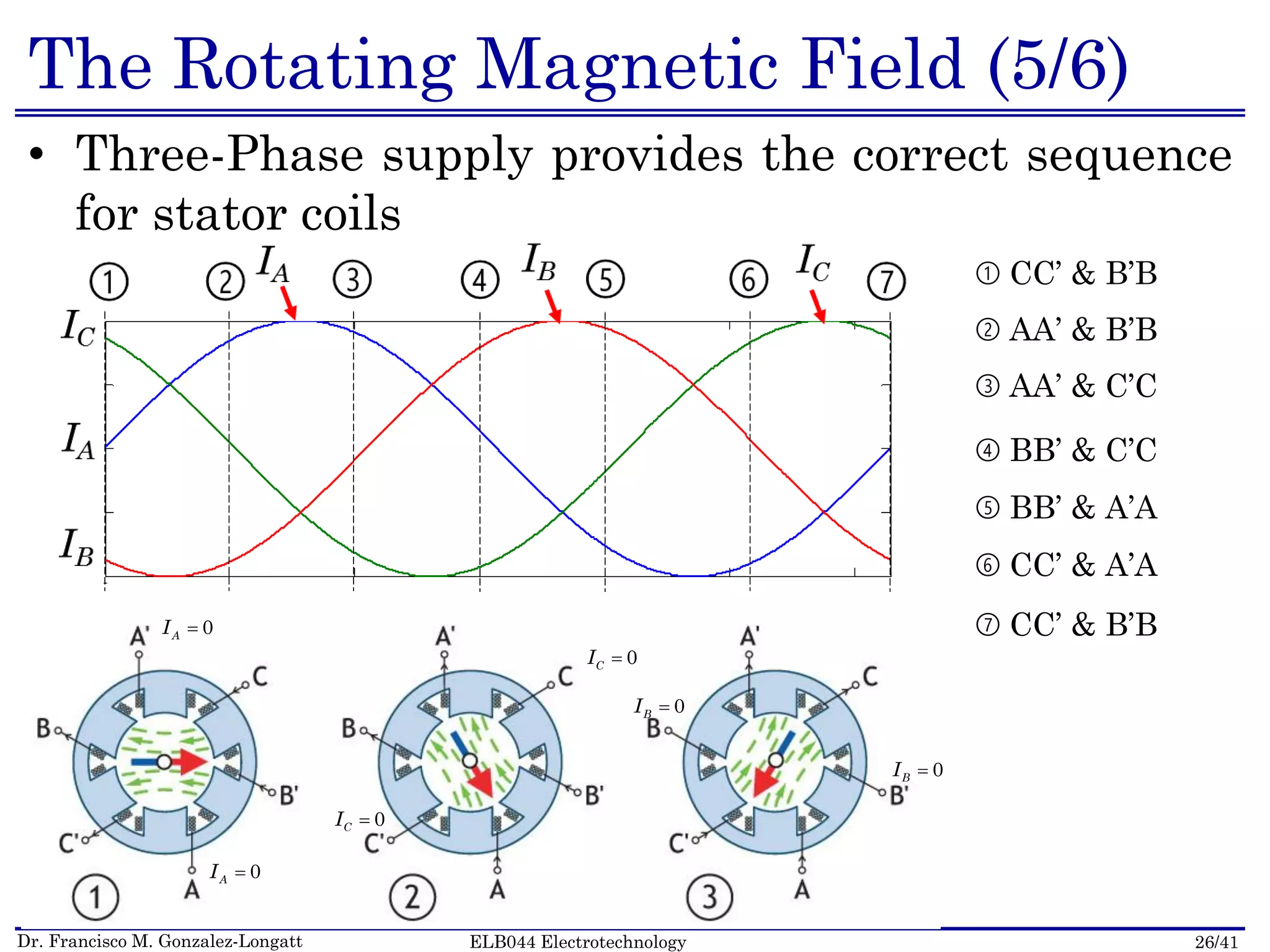
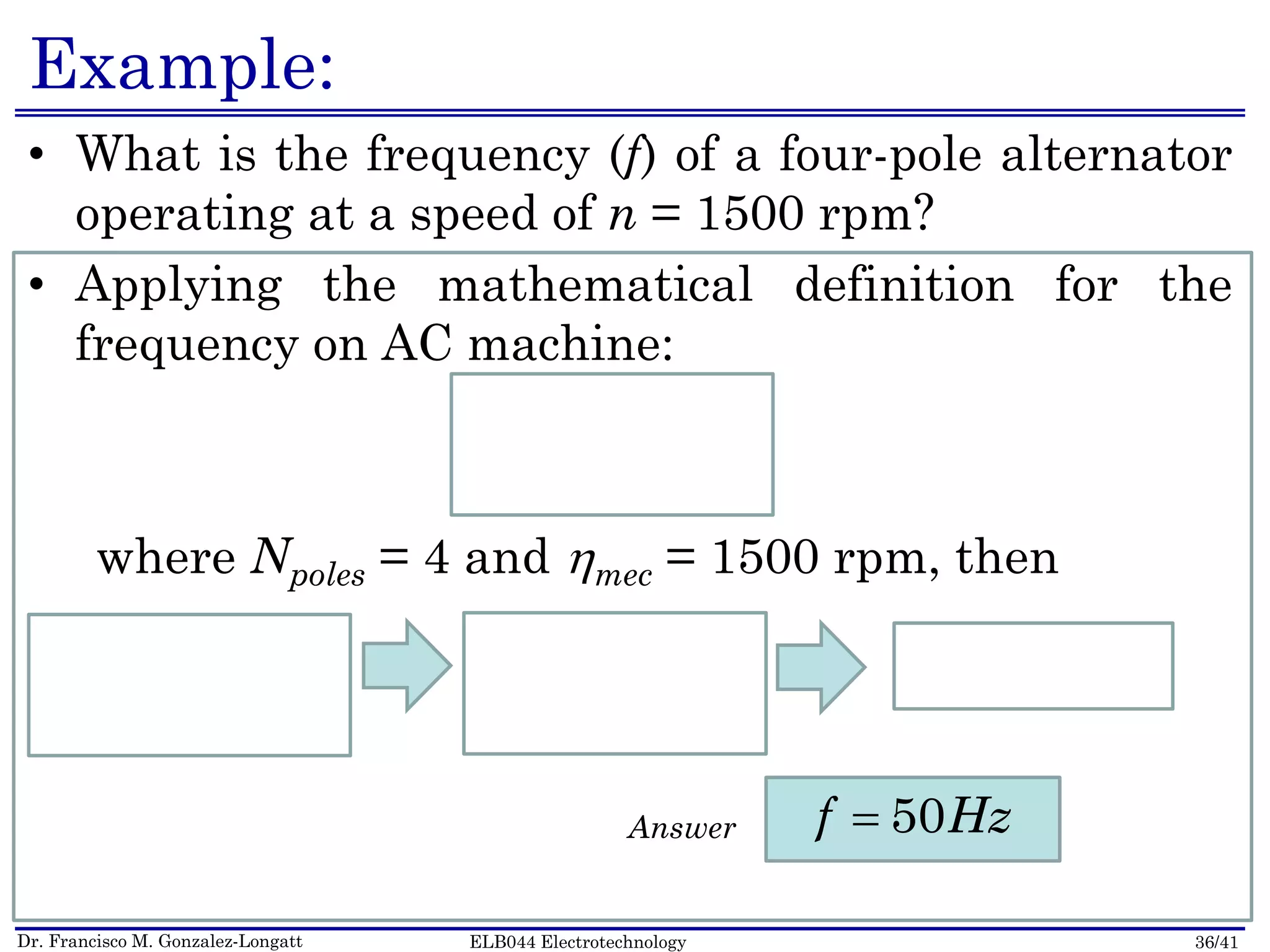
Rotational Speed (2/4)
• The mechanical speed of rotation of the magnetic
field equals to the electrical frequency (Two Pole
Machine) a’
b
c’
a
b’
c
ω
N
ω
S
SB
ω[ ] [ ] mf Hz f rps
[ ] [ ]
sec sec
e m
rad rad
Two
Poles
Machine N S](https://image.slidesharecdn.com/elb044lecture18-150528121635-lva1-app6891/75/ELB044-Lecture-18-Introduction-to-Induction-Machines-30-2048.jpg)
![Dr. Francisco M. Gonzalez-Longatt 32/41ELB044 Electrotechnology
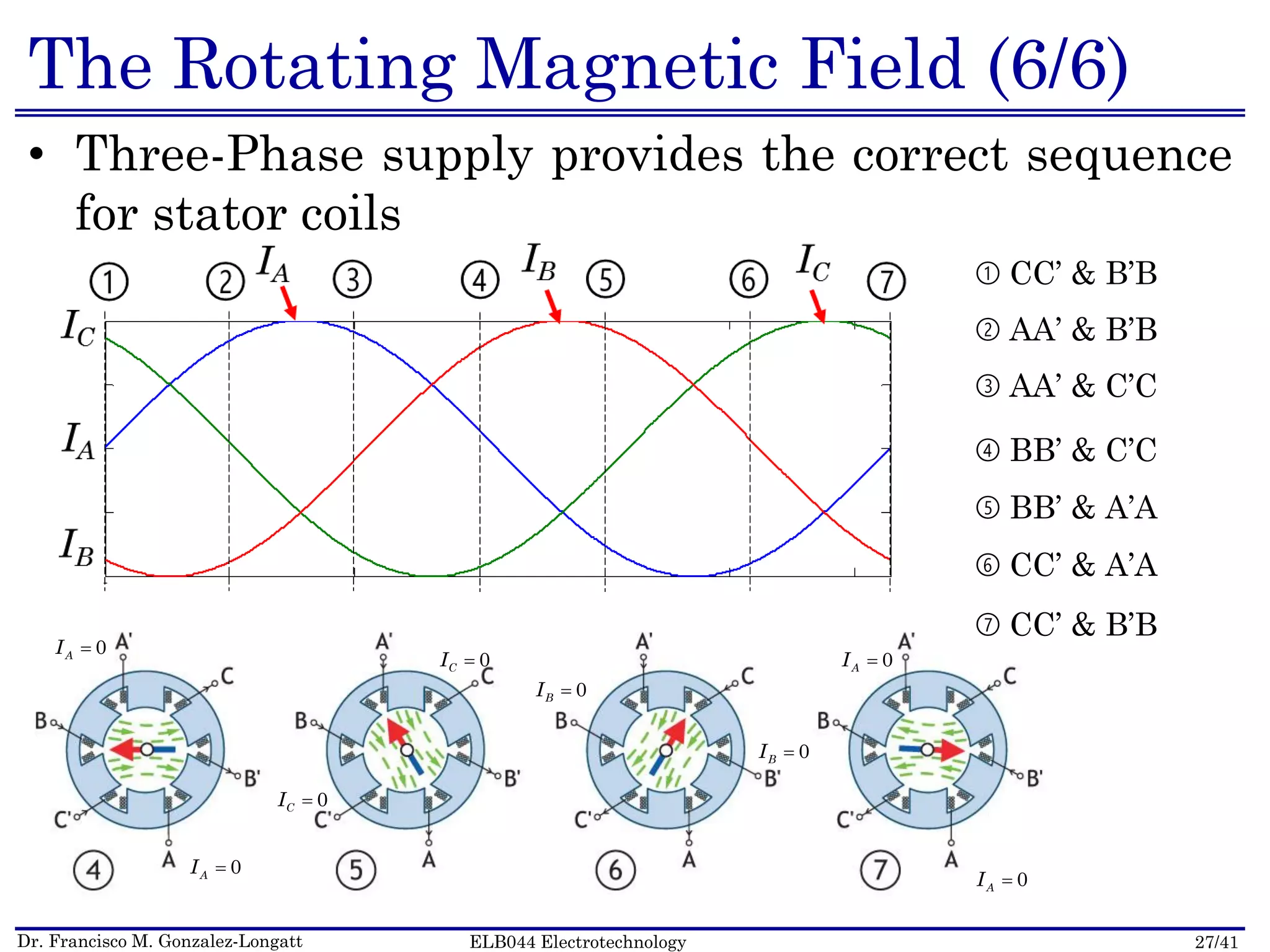
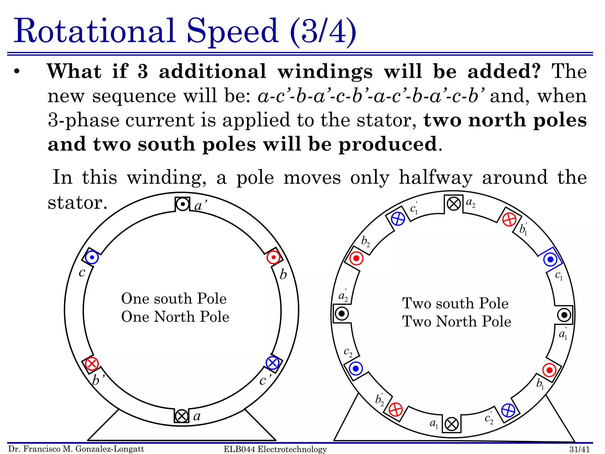
Rotational Speed (4/4)
• The relationship between the electrical angle e
(current’s phase change) and the mechanical angle m
(at which the magnetic field rotates) in this situation is:
• Therefore, for a four-pole stator:
2a
'
1b
1c
'
1a
1b
'
2c
1a
'
2b
2c
'
2a
2b
'
1c
mB B
B B
S
S N
N
m
m
m
2e m
[ ] [ ] mf Hz f rps
[ ] [ ]
sec sec
e m
rad rad
Four
Poles
Machine](https://image.slidesharecdn.com/elb044lecture18-150528121635-lva1-app6891/75/ELB044-Lecture-18-Introduction-to-Induction-Machines-32-2048.jpg)
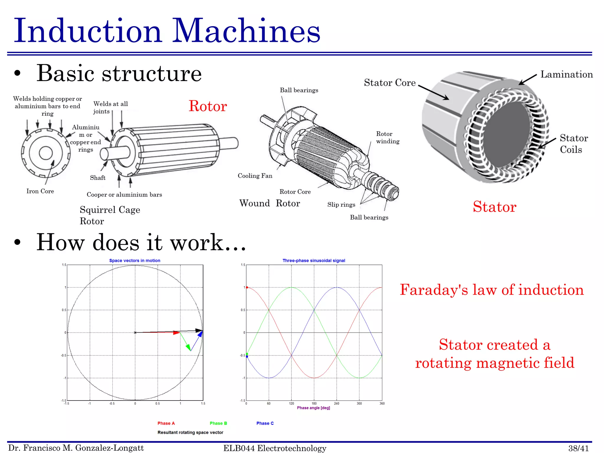

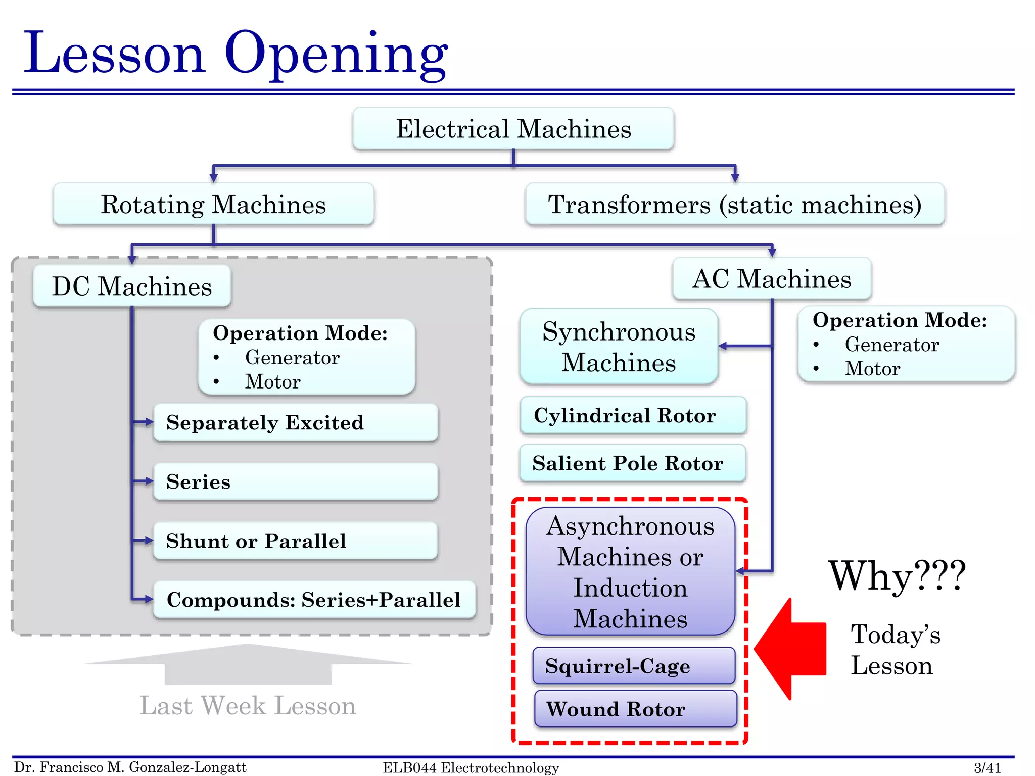
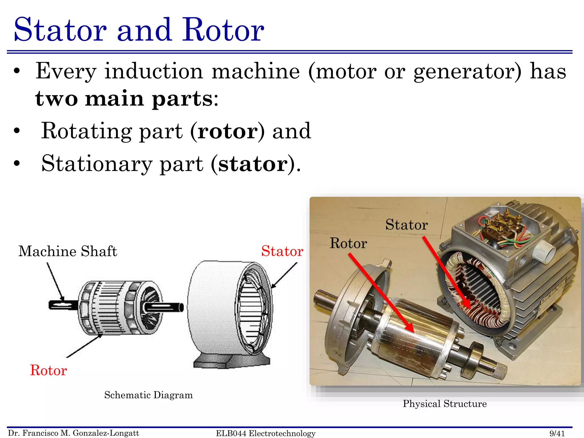
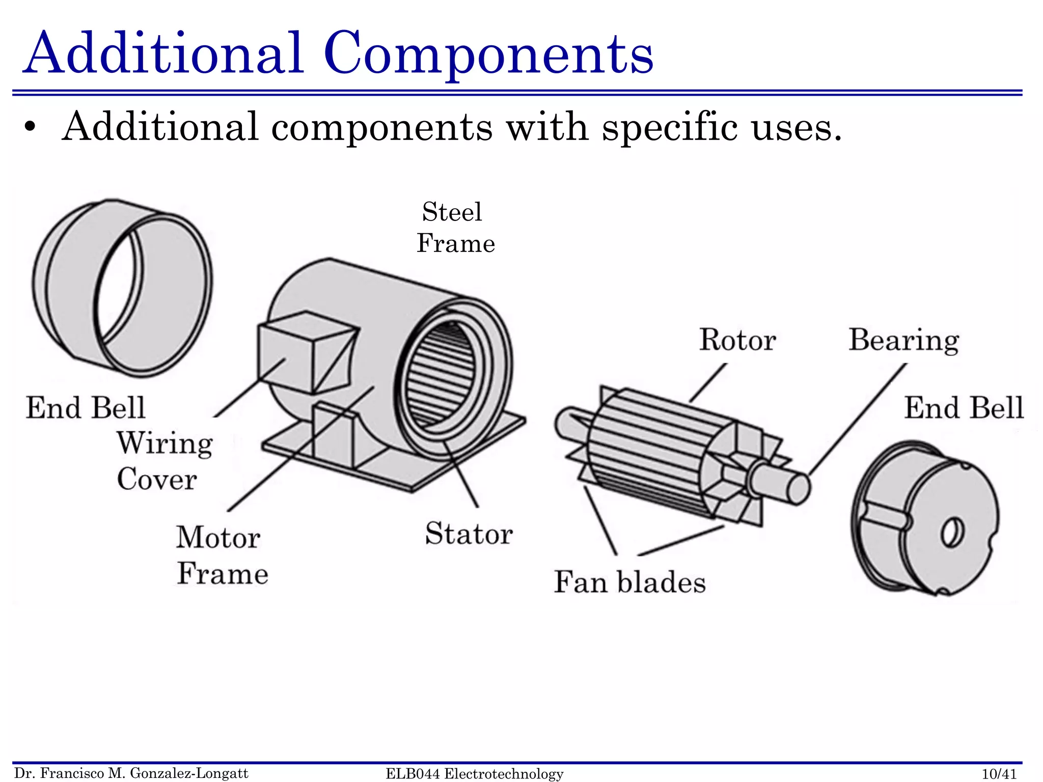
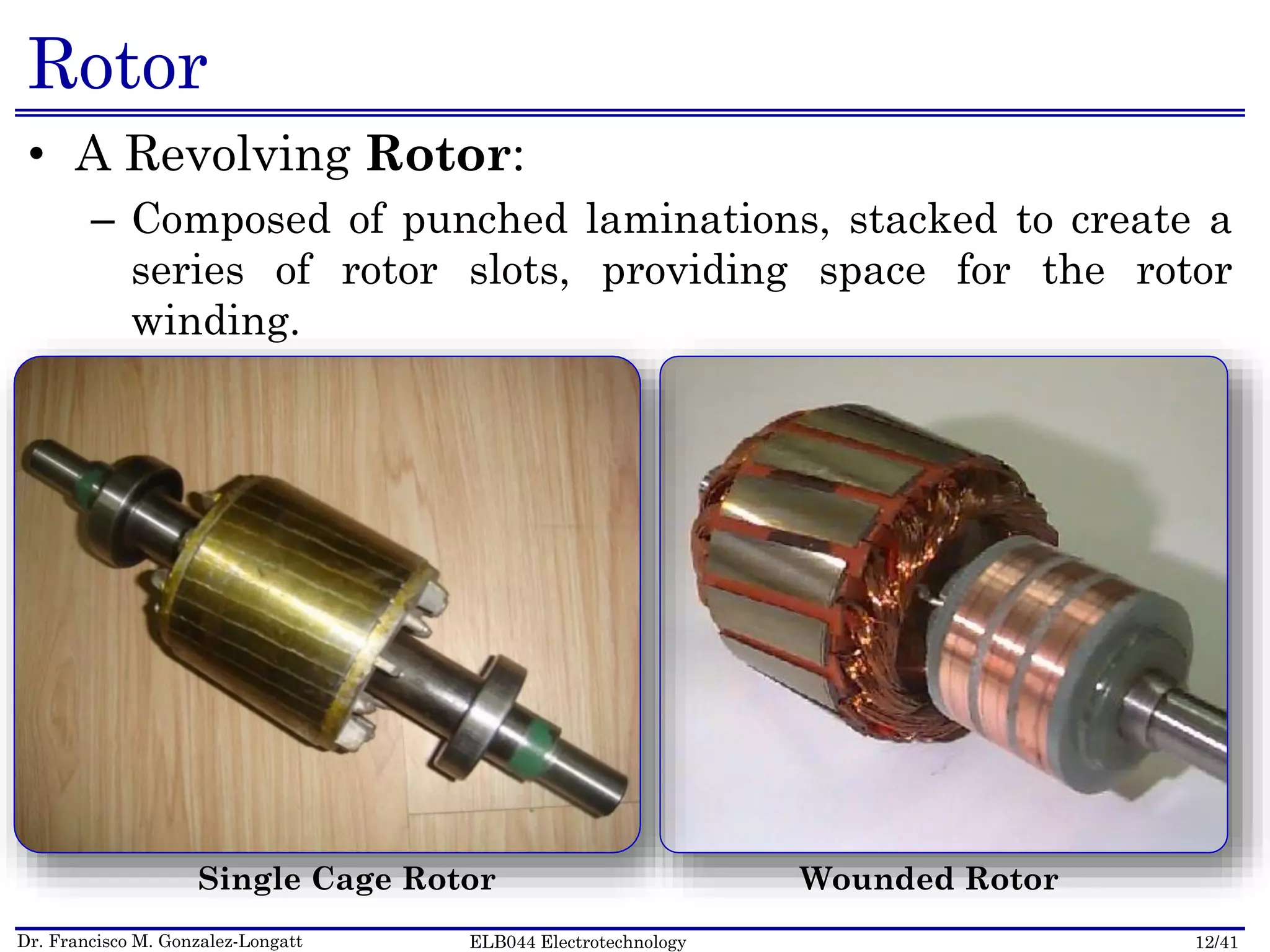
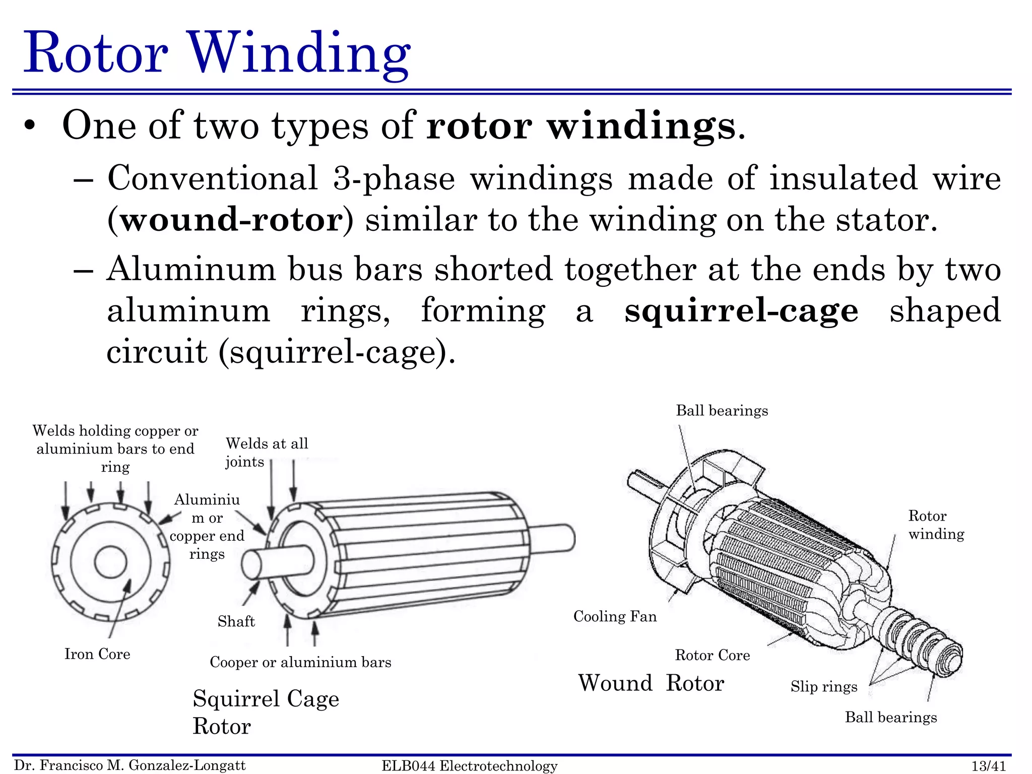
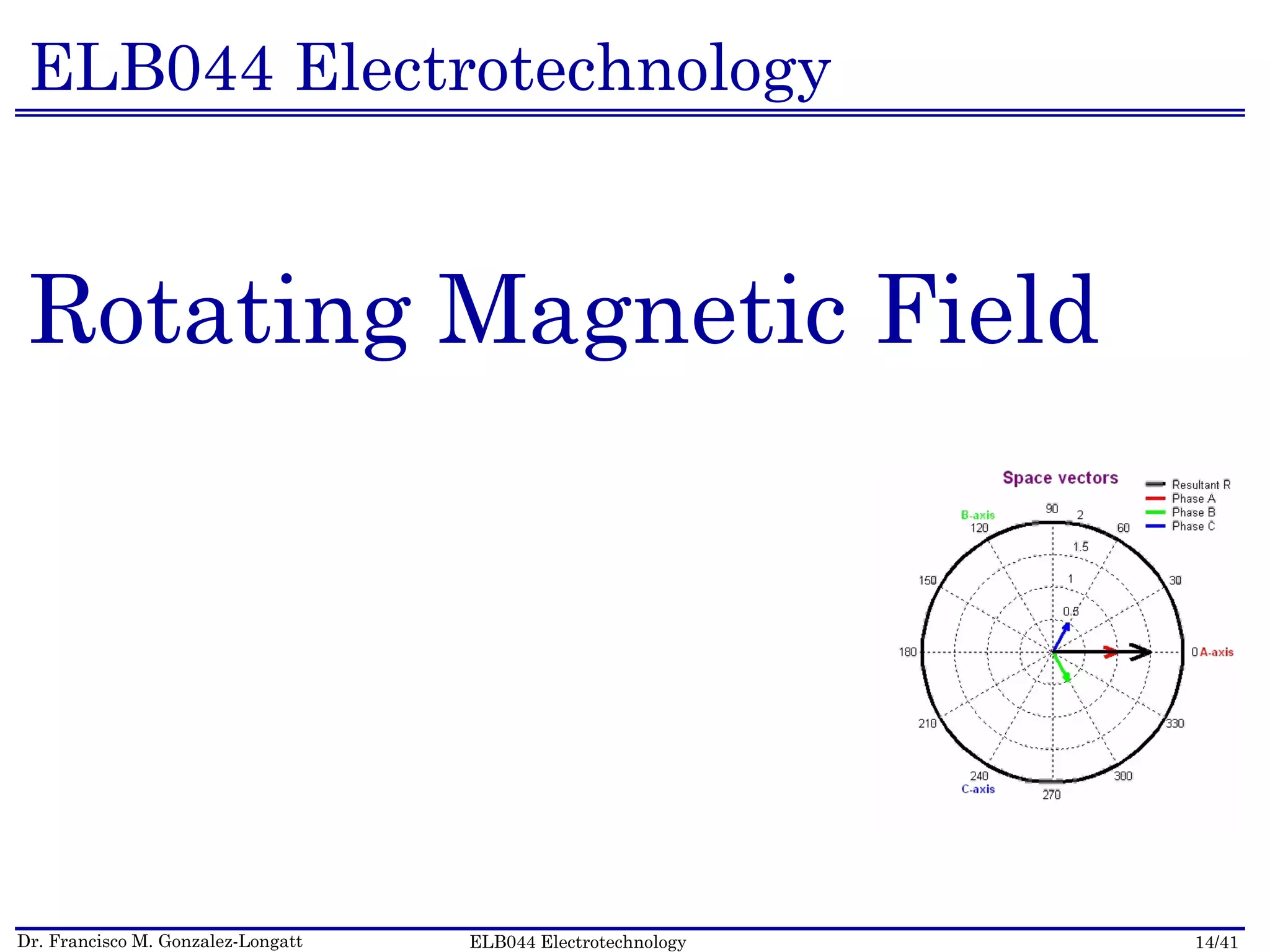
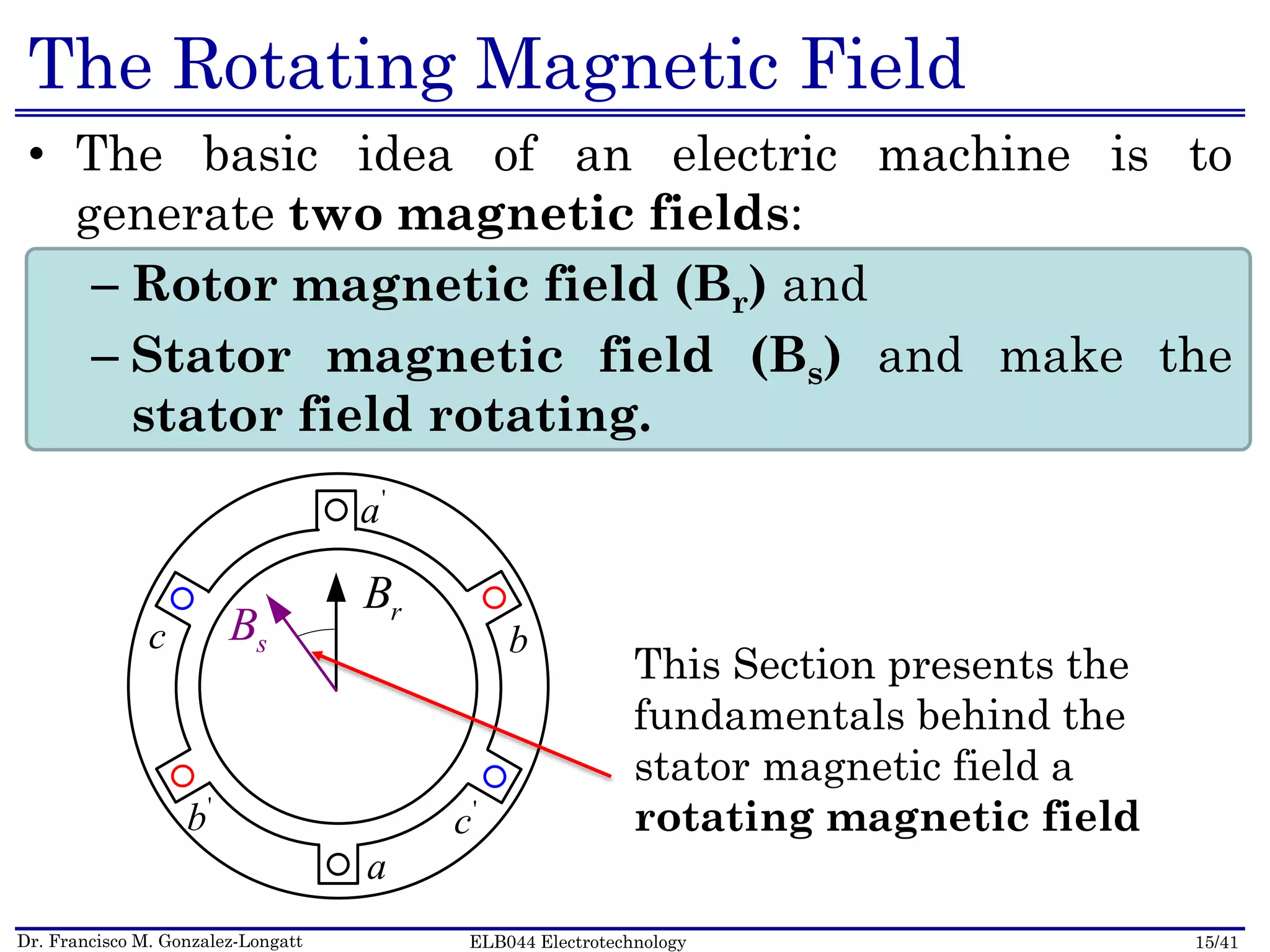
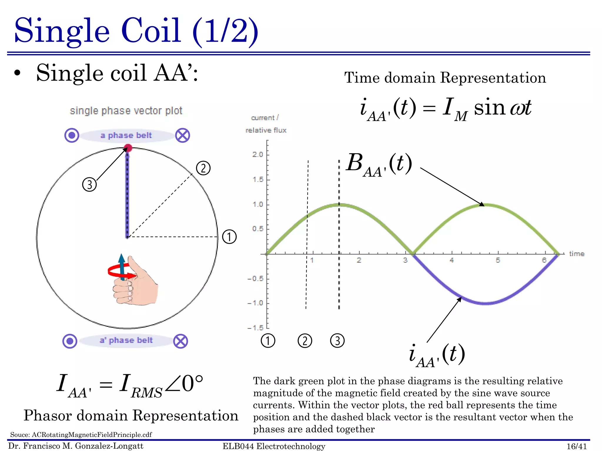
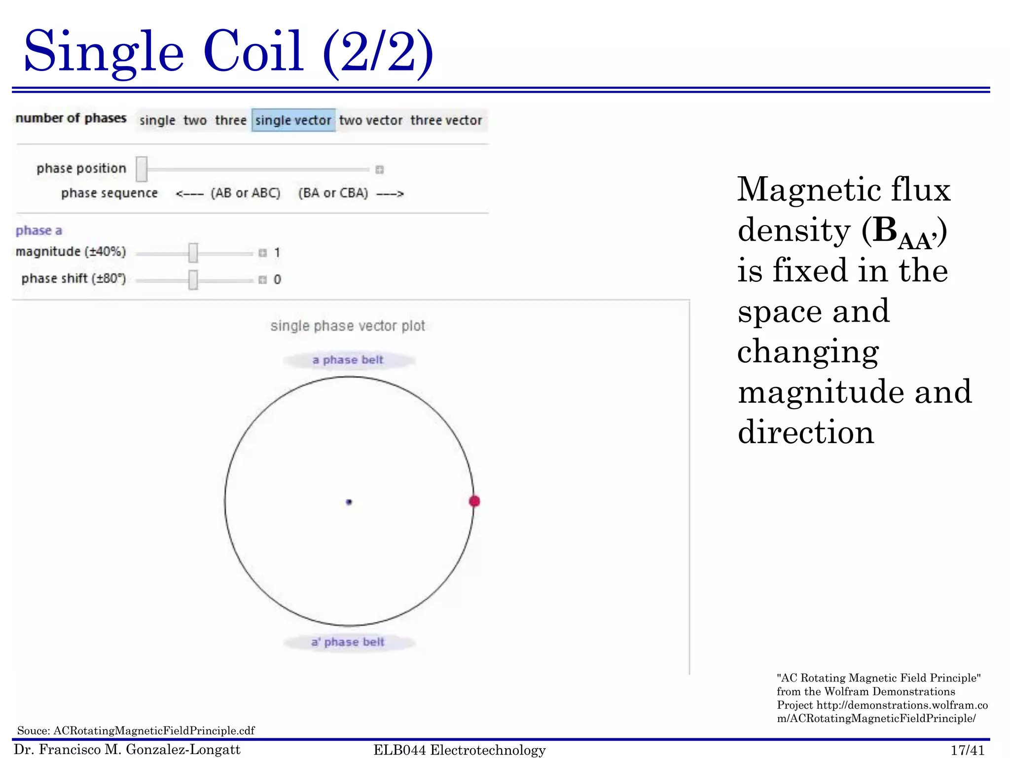
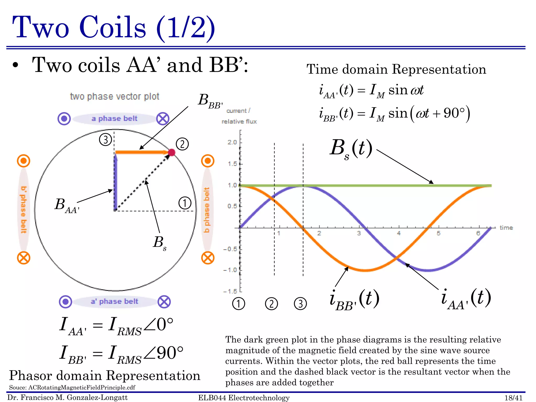
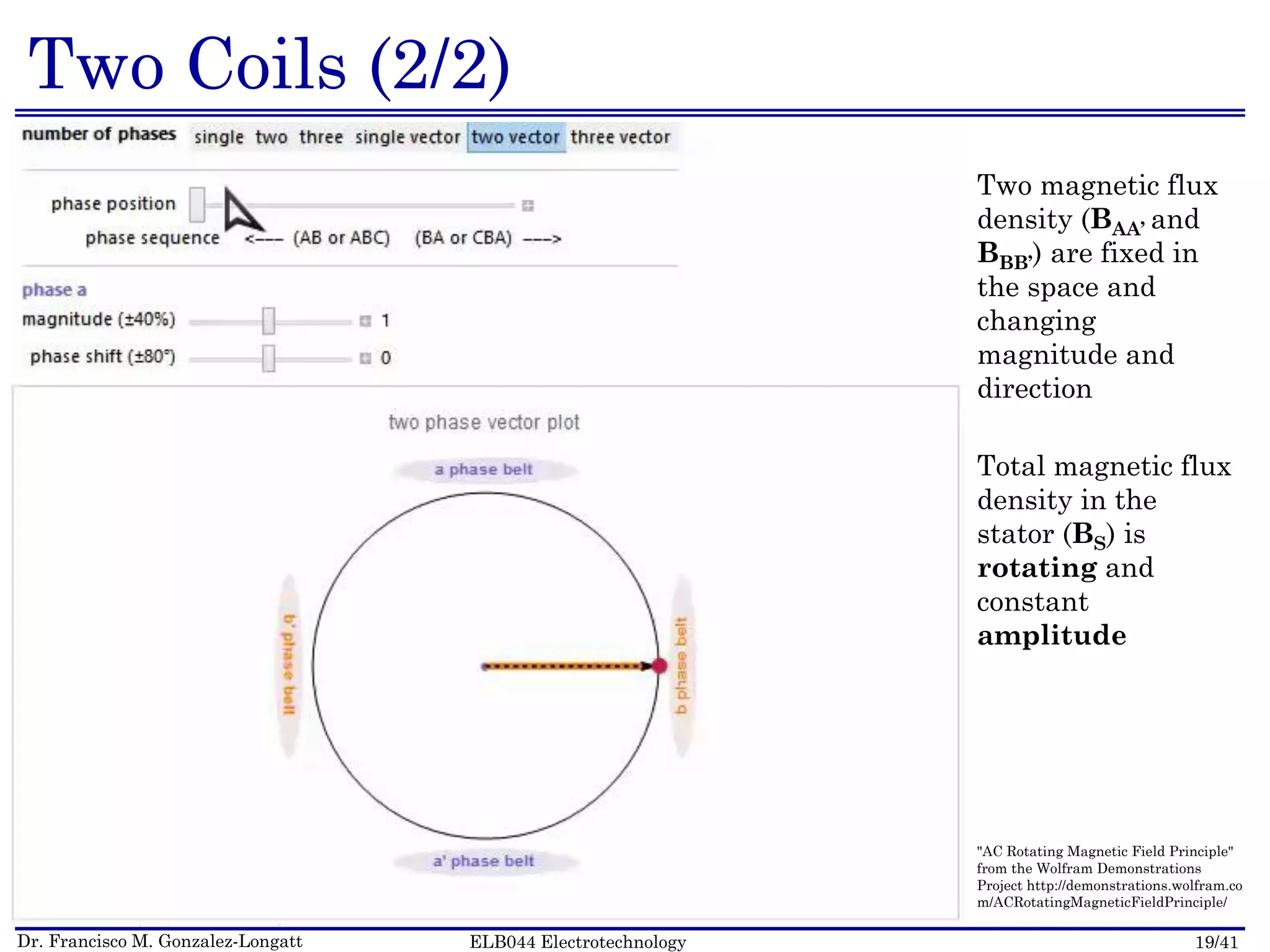
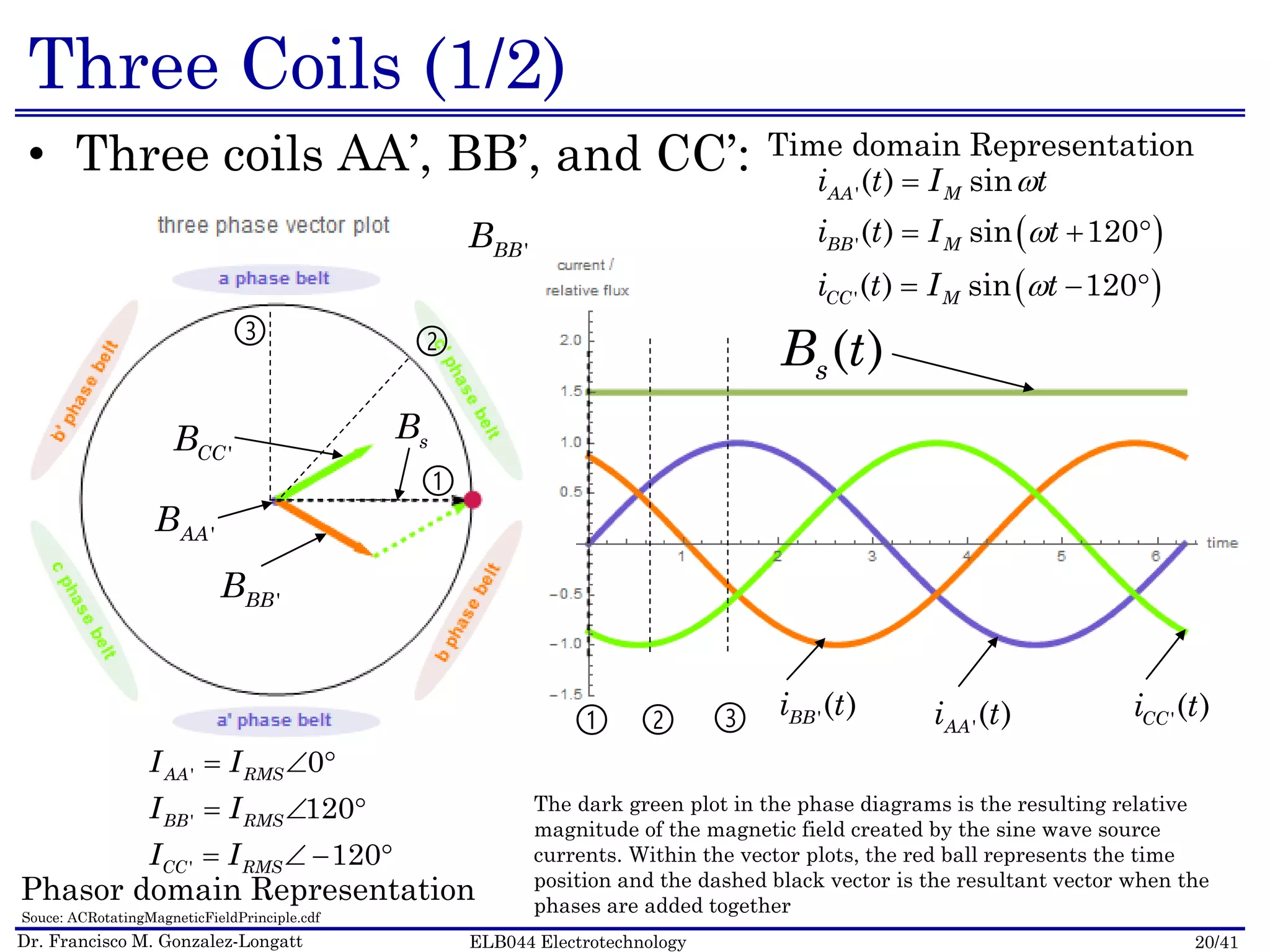
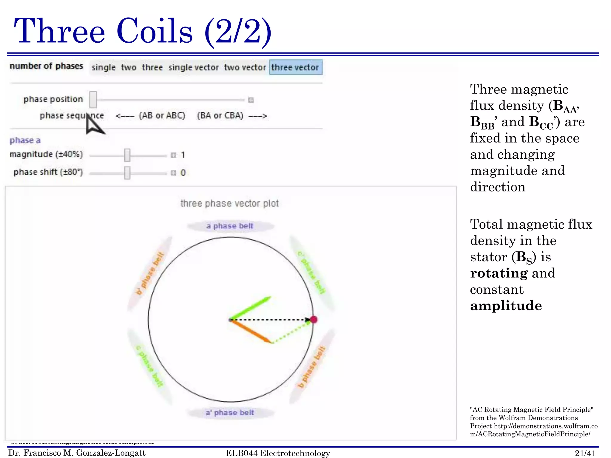
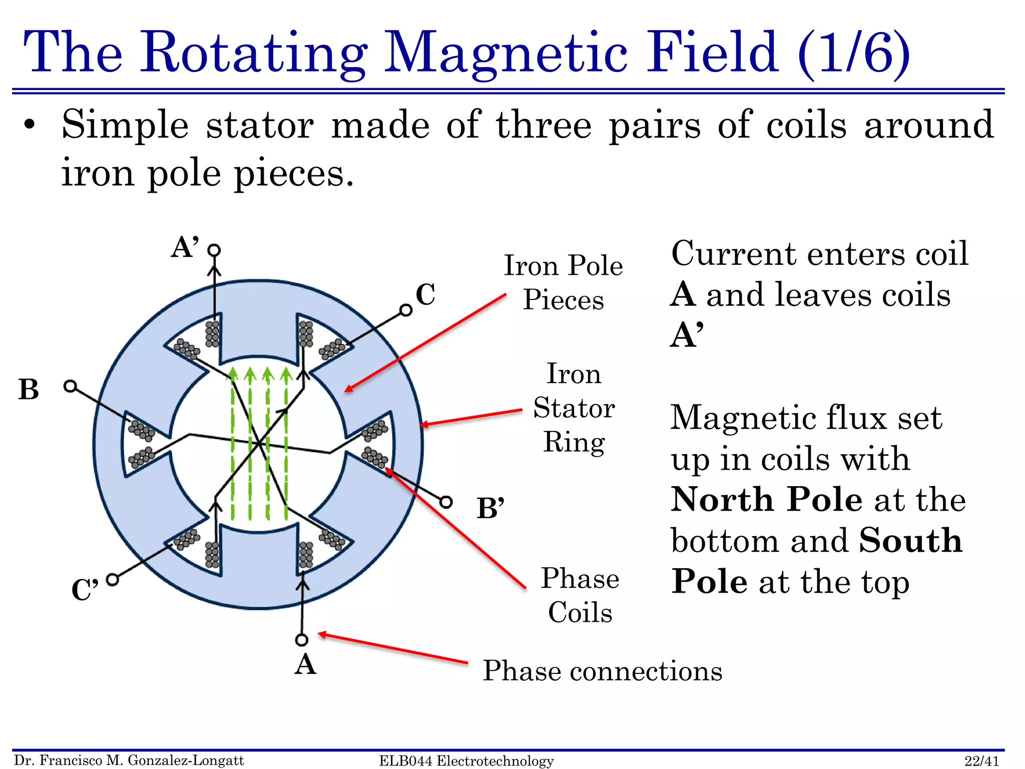
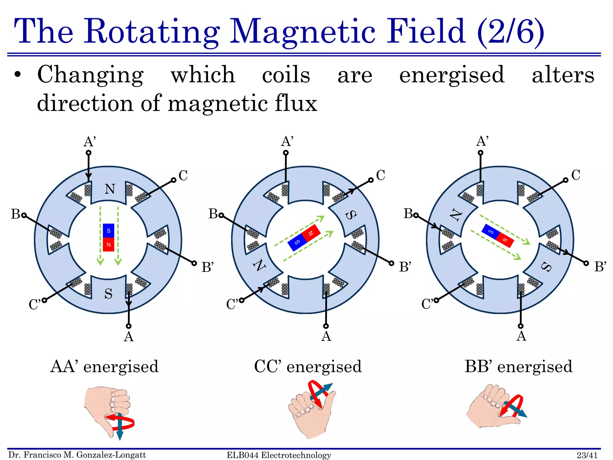
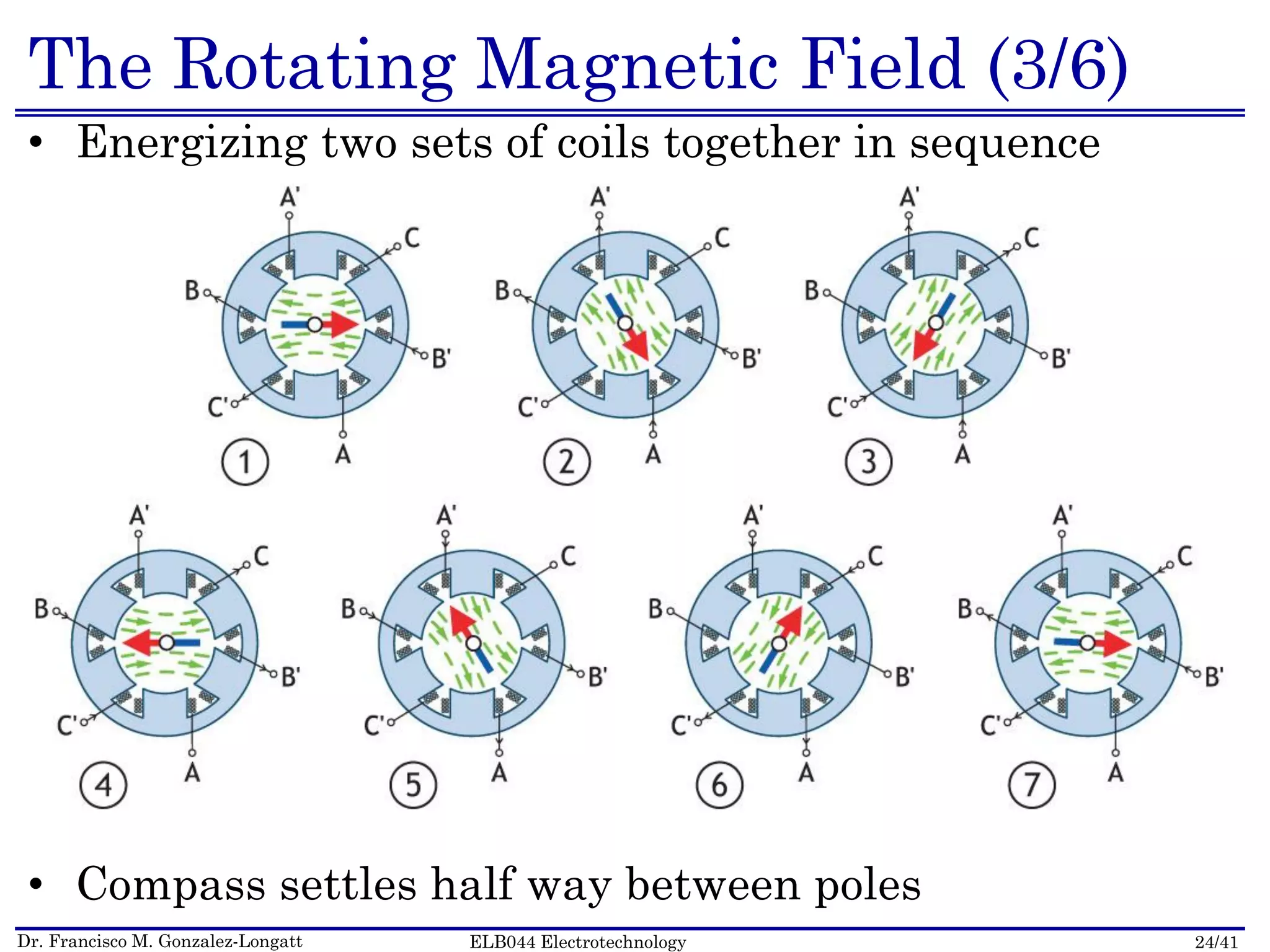
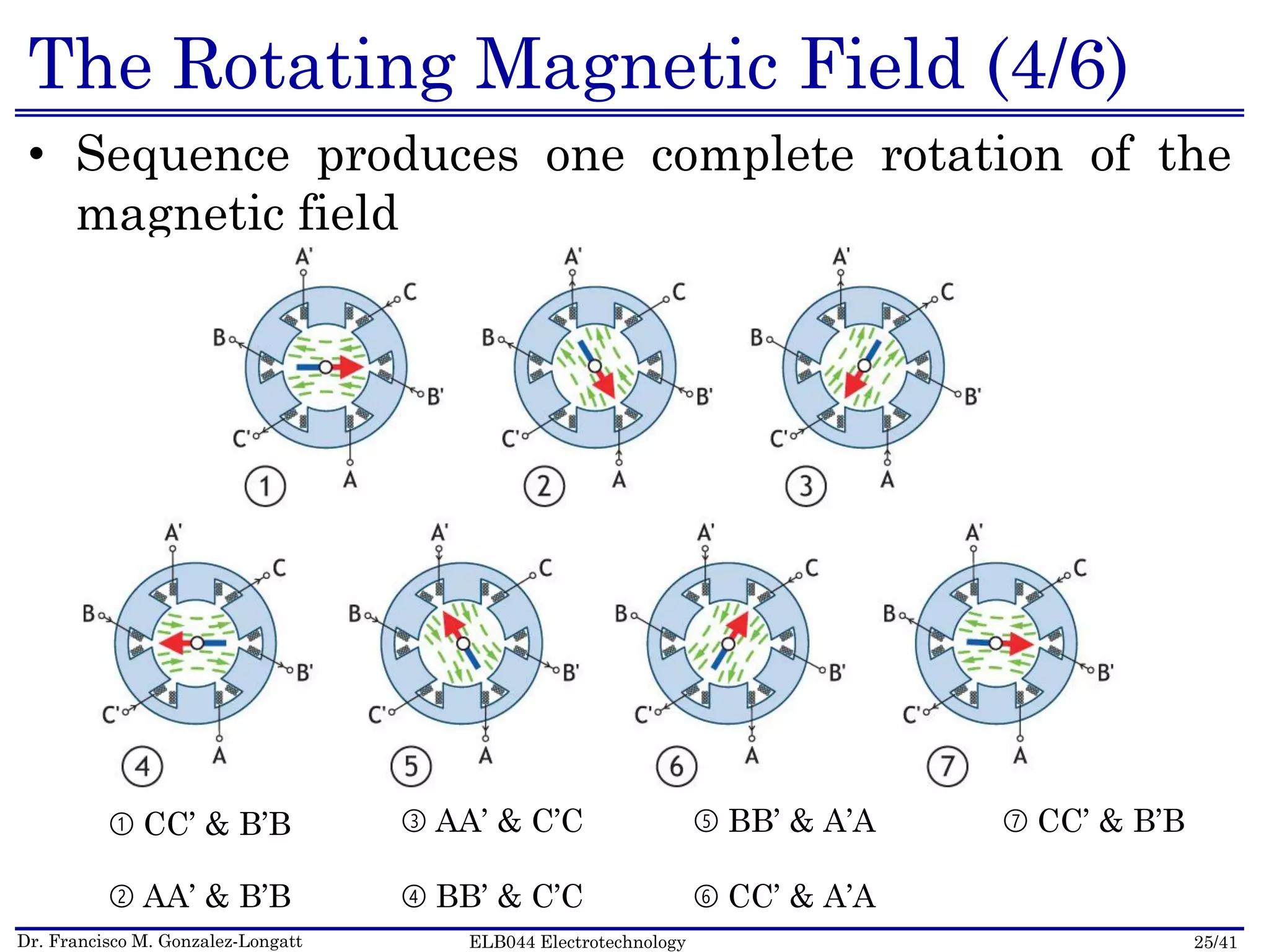
This document outlines a lecture on induction machines. It begins with an agenda and objectives. It then discusses the basic structure of induction machines, including the stator, rotor, and additional components. A key point is that the stator produces a rotating magnetic field when powered by a three-phase AC supply, which induces current in the rotor. Diagrams and animations are provided to illustrate this rotating magnetic field. The document also discusses topics like rotor windings and the relationship between electrical frequency and magnetic field rotational speed.


![Incomplete PPT on first topic.pptx [Autosaved] [Autosaved].ppt](https://cdn.slidesharecdn.com/ss_thumbnails/incompletepptonfirsttopic-230311215449-64eb2ec5-thumbnail.jpg?width=640&height=640&fit=bounds)


