UNIT IV -INDUCTION MACHINES
Induction motor:- Construction and principle of
operation, Classification of induction motor,
Torque equation, Condition for maximum torque,
Equivalent Circuit, Starting methods and Speed
control of induction motors.
2.
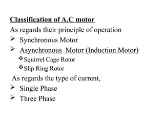
Classification of A.Cmotor
As regards their principle of operation
Synchronous Motor
Asynchronous Motor (Induction Motor)
Squirrel Cage Rotor
Slip Ring Rotor
As regards the type of current,
Single Phase
Three Phase
3.
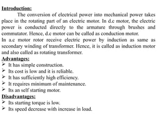
Introduction:
The conversion ofelectrical power into mechanical power takes
place in the rotating part of an electric motor. In d.c motor, the electric
power is conducted directly to the armature through brushes and
commutator. Hence, d.c motor can be called as conduction motor.
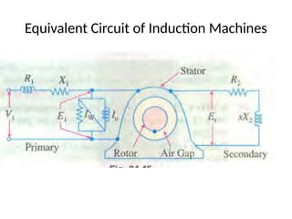
In a.c motor rotor receive electric power by induction as same as
secondary winding of transformer. Hence, it is called as induction motor
and also called as rotating transformer.
Advantages:
It has simple construction.
Its cost is low and it is reliable.
It has sufficiently high efficiency.
It requires minimum of maintenance.
Its an self starting motor.
Disadvantages:
Its starting torque is low.
Its speed decrease with increase in load.
4.
4
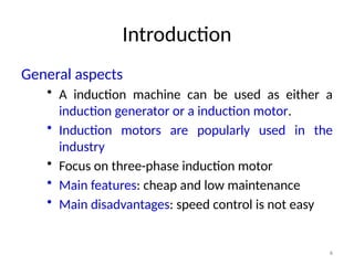
Introduction
General aspects
• Ainduction machine can be used as either a
induction generator or a induction motor.
• Induction motors are popularly used in the
industry
• Focus on three-phase induction motor
• Main features: cheap and low maintenance
• Main disadvantages: speed control is not easy
5.
Introduction
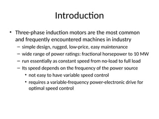
• Three-phase inductionmotors are the most common
and frequently encountered machines in industry
– simple design, rugged, low-price, easy maintenance
– wide range of power ratings: fractional horsepower to 10 MW
– run essentially as constant speed from no-load to full load
– Its speed depends on the frequency of the power source
• not easy to have variable speed control
• requires a variable-frequency power-electronic drive for
optimal speed control
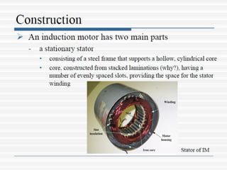
• The threebasic parts of an AC motor are the
rotor, stator, and enclosure.
• The stator and the rotor are electrical circuits
that perform as electromagnets.
10.
MZS
FKEE, UMP
10
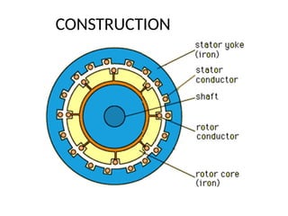
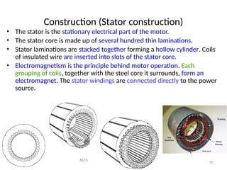
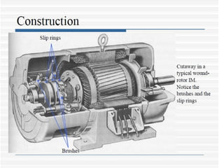
Construction (Statorconstruction)
• The stator is the stationary electrical part of the motor.
• The stator core is made up of several hundred thin laminations.
• Stator laminations are stacked together forming a hollow cylinder. Coils
of insulated wire are inserted into slots of the stator core.
• Electromagnetism is the principle behind motor operation. Each
grouping of coils, together with the steel core it surrounds, form an
electromagnet. The stator windings are connected directly to the power
source.
11.
11
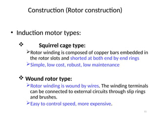
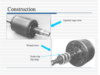
• Induction motortypes:
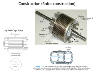
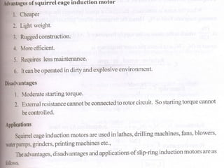
Squirrel cage type:
Rotor winding is composed of copper bars embedded in
the rotor slots and shorted at both end by end rings
Simple, low cost, robust, low maintenance
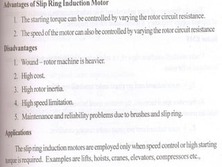
Wound rotor type:
Rotor winding is wound by wires. The winding terminals
can be connected to external circuits through slip rings
and brushes.
Easy to control speed, more expensive.
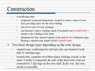
Construction (Rotor construction)
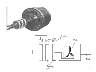
Wound rotor
• Usedin high starting torque requirements
• 3-phase windings are internally connected to
form an internal neutral connection
• Other 3 ends are connected to the slip-rings
• With the brushes riding on the slip-rings, we
can add external resistances in the rotor
circuit - can control the developed torque
15
EE2802
18
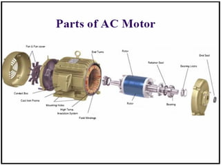
Construction (Enclosure)
• Theenclosure consists of a frame (or yoke) and two end
brackets (or bearing housings). The stator is mounted inside the
frame. The rotor fits inside the stator with a slight air gap
separating it from the stator. There is NO direct physical
connection between the rotor and the stator.
Stator
Rotor
Air gap
• The enclosure also protects the electrical
and operating parts of the motor from
harmful effects of the environment in which
the motor operates. Bearings, mounted on
the shaft, support the rotor and allow it to
turn. A fan, also mounted on the shaft, is
used on the motor shown below for cooling.
20.
20
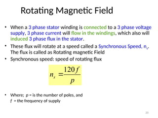
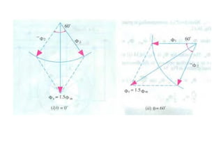
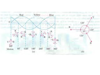
Rotating Magnetic Field
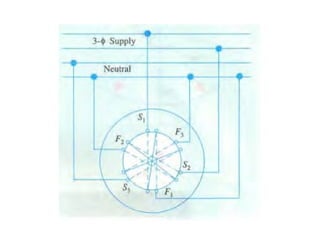
•When a 3 phase stator winding is connected to a 3 phase voltage
supply, 3 phase current will flow in the windings, which also will
induced 3 phase flux in the stator.
• These flux will rotate at a speed called a Synchronous Speed, ns.
The flux is called as Rotating magnetic Field
• Synchronous speed: speed of rotating flux
• Where; p = is the number of poles, and
f = the frequency of supply
p
f
ns
120
21.
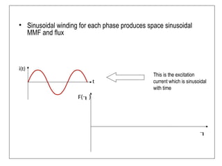
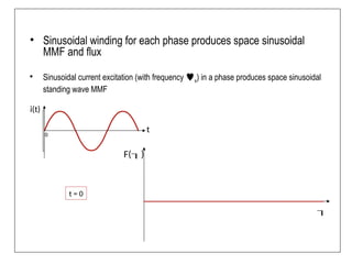
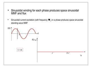
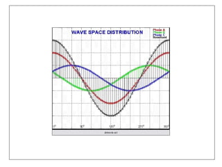
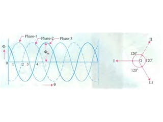
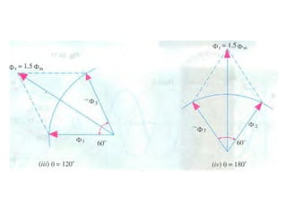
• Sinusoidal windingfor each phase produces space sinusoidal
MMF and flux
F()
t
i(t)
This is the excitation
current which is sinusoidal
with time
22.
• Sinusoidal windingfor each phase produces space sinusoidal
MMF and flux
• Sinusoidal current excitation (with frequency s) in a phase produces space sinusoidal
standing wave MMF
F()
t
i(t)
t = 0
0
23.
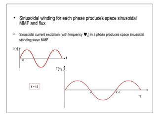
• Sinusoidal windingfor each phase produces space sinusoidal
MMF and flux
• Sinusoidal current excitation (with frequency s) in a phase produces space sinusoidal
standing wave MMF
F()
t
i(t)
2
t = t1
t1
24.
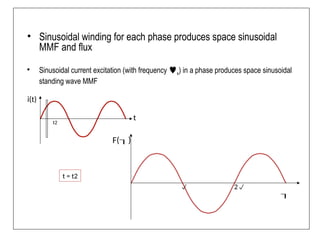
• Sinusoidal windingfor each phase produces space sinusoidal
MMF and flux
• Sinusoidal current excitation (with frequency s) in a phase produces space sinusoidal
standing wave MMF
F()
t
i(t)
2
t = t2
t2
25.
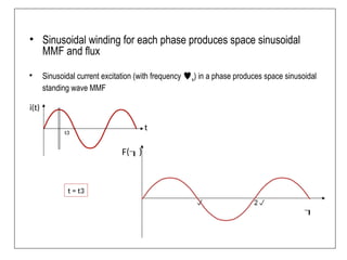
• Sinusoidal windingfor each phase produces space sinusoidal
MMF and flux
• Sinusoidal current excitation (with frequency s) in a phase produces space sinusoidal
standing wave MMF
F()
t
i(t)
2
t = t3
t3
26.
• Sinusoidal windingfor each phase produces space sinusoidal
MMF and flux
• Sinusoidal current excitation (with frequency s) in a phase produces space sinusoidal
standing wave MMF
F()
t
i(t)
2
t = t4
t4
27.
• Sinusoidal windingfor each phase produces space sinusoidal
MMF and flux
• Sinusoidal current excitation (with frequency s) in a phase produces space sinusoidal
standing wave MMF
F()
t
i(t)
2
t = t5
t5
28.
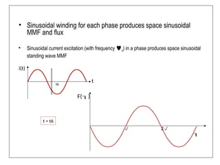
• Sinusoidal windingfor each phase produces space sinusoidal
MMF and flux
• Sinusoidal current excitation (with frequency s) in a phase produces space sinusoidal
standing wave MMF
F()
t
i(t)
2
t = t6
t6
29.
• Sinusoidal windingfor each phase produces space sinusoidal
MMF and flux
• Sinusoidal current excitation (with frequency s) in a phase produces space sinusoidal
standing wave MMF
F()
t
i(t)
2
t = t7
t7
30.
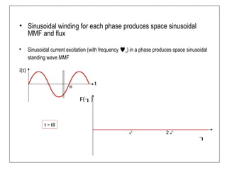
• Sinusoidal windingfor each phase produces space sinusoidal
MMF and flux
• Sinusoidal current excitation (with frequency s) in a phase produces space sinusoidal
standing wave MMF
F()
t
i(t)
2
t = t8
t8
38
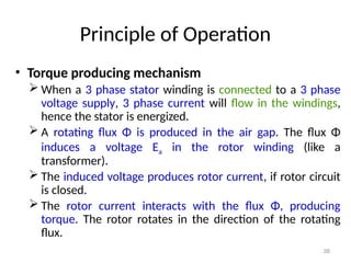
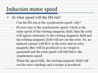
Principle of Operation
•Torque producing mechanism
When a 3 phase stator winding is connected to a 3 phase
voltage supply, 3 phase current will flow in the windings,
hence the stator is energized.
A rotating flux Φ is produced in the air gap. The flux Φ
induces a voltage Ea in the rotor winding (like a
transformer).
The induced voltage produces rotor current, if rotor circuit
is closed.
The rotor current interacts with the flux Φ, producing
torque. The rotor rotates in the direction of the rotating
flux.
39.
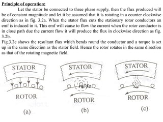
Principle of operation:
Letthe stator be connected to three phase supply, then the flux produced will
be of constant magnitude and let it be assumed that it is rotating in a counter clockwise
direction as in fig. 3.2a. When the stator flux cuts the stationary rotor conductors an
emf is induced in it. This emf will cause to flow the current when the rotor conductor is
in close path due the current flow it will produce the flux in clockwise direction as fig.
3.2b.
Fig.3.2c shows the resultant flux which bends round the conductor and a torque is set
up in the same direction as the stator field. Hence the rotor rotates in the same direction
as that of the rotating magnetic field.
Fig. 3.2
40.
40
Direction of RotorRotates
• Q: How to change the direction of
• rotation?
• • A: Change the phase sequence of the
• power supply.
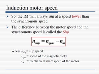
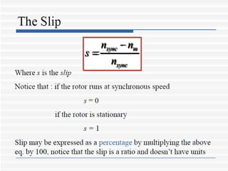
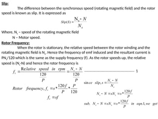
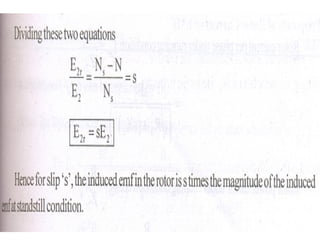
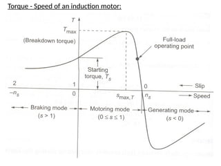
Slip:
The difference betweenthe synchronous speed (rotating magnetic field) and the rotor
speed is known as slip. It is expressed as
Where, Ns – speed of the rotating magnetic field
N – Motor speed.
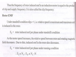
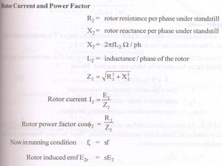
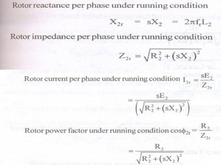
Rotor Frequency:
When the rotor is stationary, the relative speed between the rotor winding and the
rotating magnetic field is Ns. Hence the frequency of emf induced and the resultant current is
PNs/120 which is the same as the supply frequency (f). As the rotor speeds up, the relative
speed is (Ns-N) and hence the rotor frequency is
s
S
Slip
N
N
s
)
(
N
sf
f
P
P
f
s
f
frequency
Rotor
P
N
N
P
rpm
in
speed
lative
f
r
r
s
r
120
*
120
*
,
120
120
Re
get
we
eqn
in
P
f
s
sN
N
N
sub
P
f
s
sN
N
N
N
N
N
s
slip
ce
s
s
s
s
s
s
,
1
.
120
*
.
120
*
,
sin
1
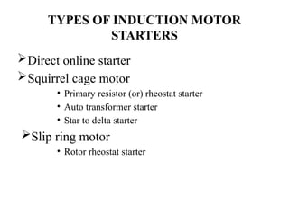
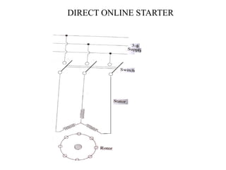
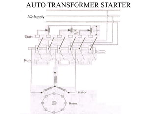
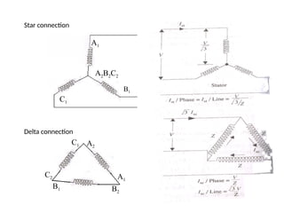
TYPES OF INDUCTIONMOTOR
STARTERS
Direct online starter
Squirrel cage motor
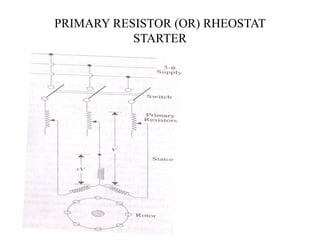
• Primary resistor (or) rheostat starter
• Auto transformer starter
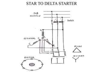
• Star to delta starter
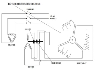
Slip ring motor
• Rotor rheostat starter
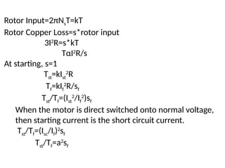
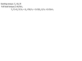
Rotor Input=2πNsT=kT
Rotor CopperLoss=s*rotor input
3I2
R=s*kT
TαI2
R/s
At starting, s=1
Tst=kIst
2
R
Tf=kIf
2
R/sf
Tst/Tf=(Ist
2
/If
2
)sf
When the motor is direct switched onto normal voltage,
then starting current is the short circuit current.
Tst/Tf=(Isc/If)2
sf
Tst/Tf=a2
sf
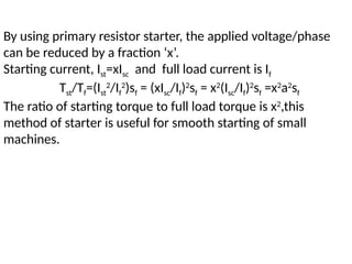
By using primaryresistor starter, the applied voltage/phase
can be reduced by a fraction ‘x’.
Starting current, Ist=xIsc and full load current is If
Tst/Tf=(Ist
2
/If
2
)sf = (xIsc/If)2
sf = x2
(Isc/If)2
sf =x2
a2
sf
The ratio of starting torque to full load torque is x2
,this
method of starter is useful for smooth starting of small
machines.
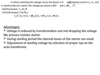
Advantages:
Voltage isreduced by transformation and not dropping the voltage
like primary resistor starter.
During starting period the internal losses of the starter are small.
Adjustment of starting voltage by selection of proper tap on the
auto transformer.
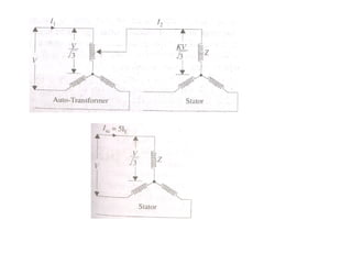
In direct switching the voltage across the phase is V/ and starting current is Ist=Isc and
in autotransformer starter, the voltage per phase is KV/ and Ist=KIsc.
Starting torque, Tst=kIst
2
R
Full load torque,Tf=kIf
2
R/sf
Tst/Tf=(Ist
2
/If
2
)sf = (KIsc/If)2
sf = K2
(Isc/If)2
sf =K2
a2
sf
3
3
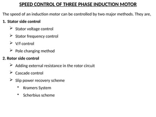
SPEED CONTROL OFTHREE PHASE INDUCTION MOTOR
The speed of an induction motor can be controlled by two major methods. They are,
1. Stator side control
Stator voltage control
Stator frequency control
V/f control
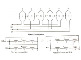
Pole changing method
2. Rotor side control
Adding external resistance in the rotor circuit
Cascade control
Slip power recovery scheme
• Kramers System
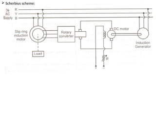
• Scherbius scheme
98.
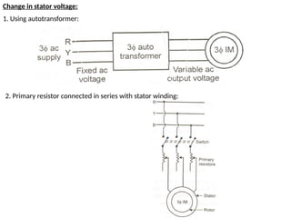
Change in statorvoltage:
1. Using autotransformer:
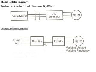
2. Primary resistor connected in series with stator winding:
99.
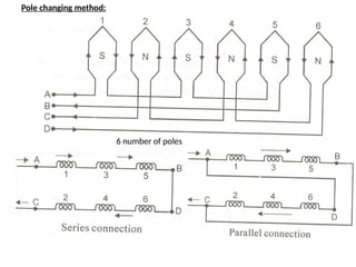
Change in statorfrequency:
Synchronous speed of the induction motor, Ns=120f/p
Voltage/ frequency control:
Rotor side control:
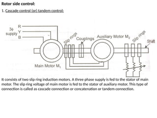
1.Cascade control (or) tandem control:
It consists of two slip ring induction motors. A three phase supply is fed to the stator of main
motor. The slip ring voltage of main motor is fed to the stator of auxiliary motor. This type of
connection is called as cascade connection or concatenation or tandem connection.
103.
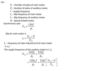
Let,
P1 – Numberof poles of main motor.
P2 - Number of poles of auxiliary motor.
f - Supply frequency
f1 – Slip frequency of main motor
f2 – Slip frequency of auxiliary motor
N – Speed of both motor.
Synchronous speed of the main motor is given by
Slip for main motor is
f1 – frequency of rotor induced emf of main motor
f1=s1f
The supply frequency of the auxiliary motor is f1=f2
104.
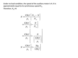
Under no loadcondition, the speed of the auxiliary motor is N. It is
approximately equal to its synchronous speed Ns2
Therefore, Ns2=N
f
Np
p
f
N
p
f
N
p
f
N
N
p
f
N
N
N
p
f
N
s
s
s
120
1
120
120
1
120
1
120
120
1
2
1
2
1
2
1
1
2
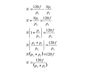
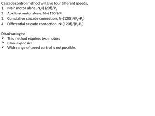
Cascade control methodwill give four different speeds,
1. Main motor alone, Ns=(120f)/P1
2. Auxiliary motor alone, Ns=(120f)/P2
3. Cumulative cascade connection, N=(120f)/(P1+P2)
4. Differential cascade connection, N=(120f)/(P1-P2)
Disadvantages:
This method requires two motors
More expensive
Wide range of speed control is not possible.
107.
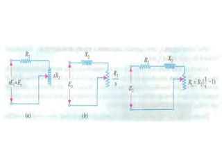
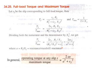
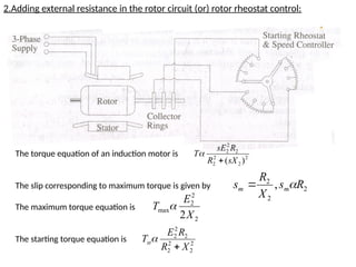
2.Adding external resistancein the rotor circuit (or) rotor rheostat control:
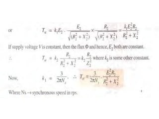
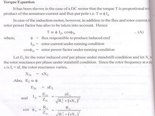
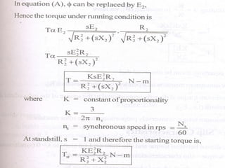
The torque equation of an induction motor is
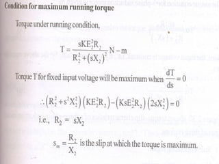
The slip corresponding to maximum torque is given by
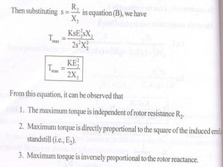
The maximum torque equation is
The starting torque equation is
2
2
2
2
2
2
2
)
(sX
R
R
sE
T
2
2
2
, R
s
X
R
s m
m
2
2
2
max
2X
E
T
2
2
2
2
2
2
2
X
R
R
E
Tst
108.
Advantages:
Smooth andwide range of speed control.
Absence of in-rush starting current.
Availability of full rated torque at starting.
Disadvantages:
Reduced efficiency because of slip power is wasted in the rotor circuit resistance.
Unbalance in voltage and current if rotor circuit resistance are not equal.
Speed changes with load variation.
109.
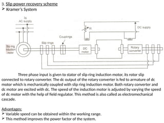
3. Slip powerrecovery scheme
Kramer’s System
Three phase input is given to stator of slip ring induction motor, its rotor slip
connected to rotary converter. The dc output of the rotary converter is fed to armature of dc
motor which is mechanically coupled with slip ring induction motor. Both rotary converter and
dc motor are excited with dc. The speed of the induction motor is adjusted by varying the speed
of dc motor with the help of field regulator. This method is also called as electromechanical
cascade.
Advantages:
Variable speed can be obtained within the working range.
This method improves the power factor of the system.