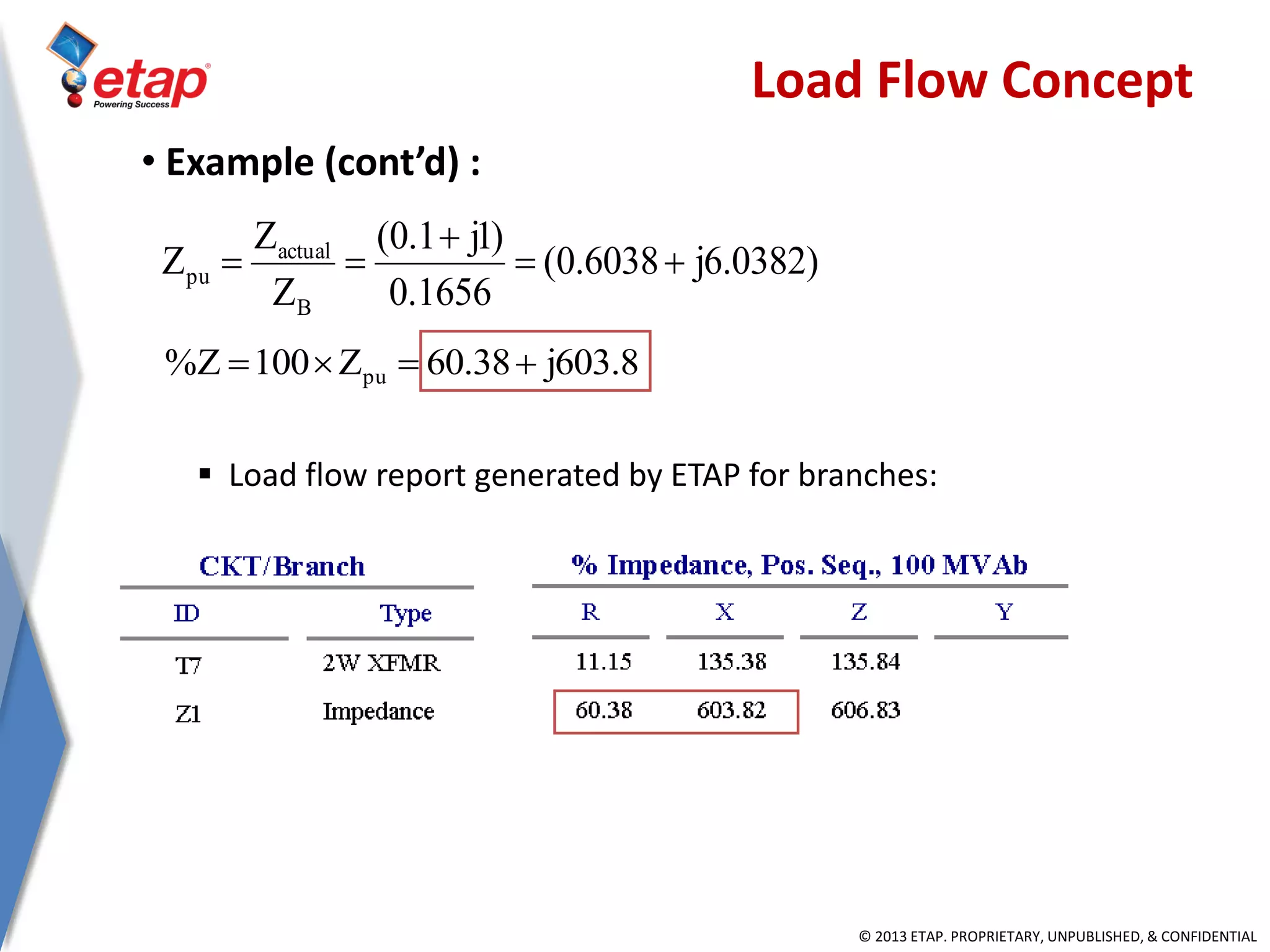
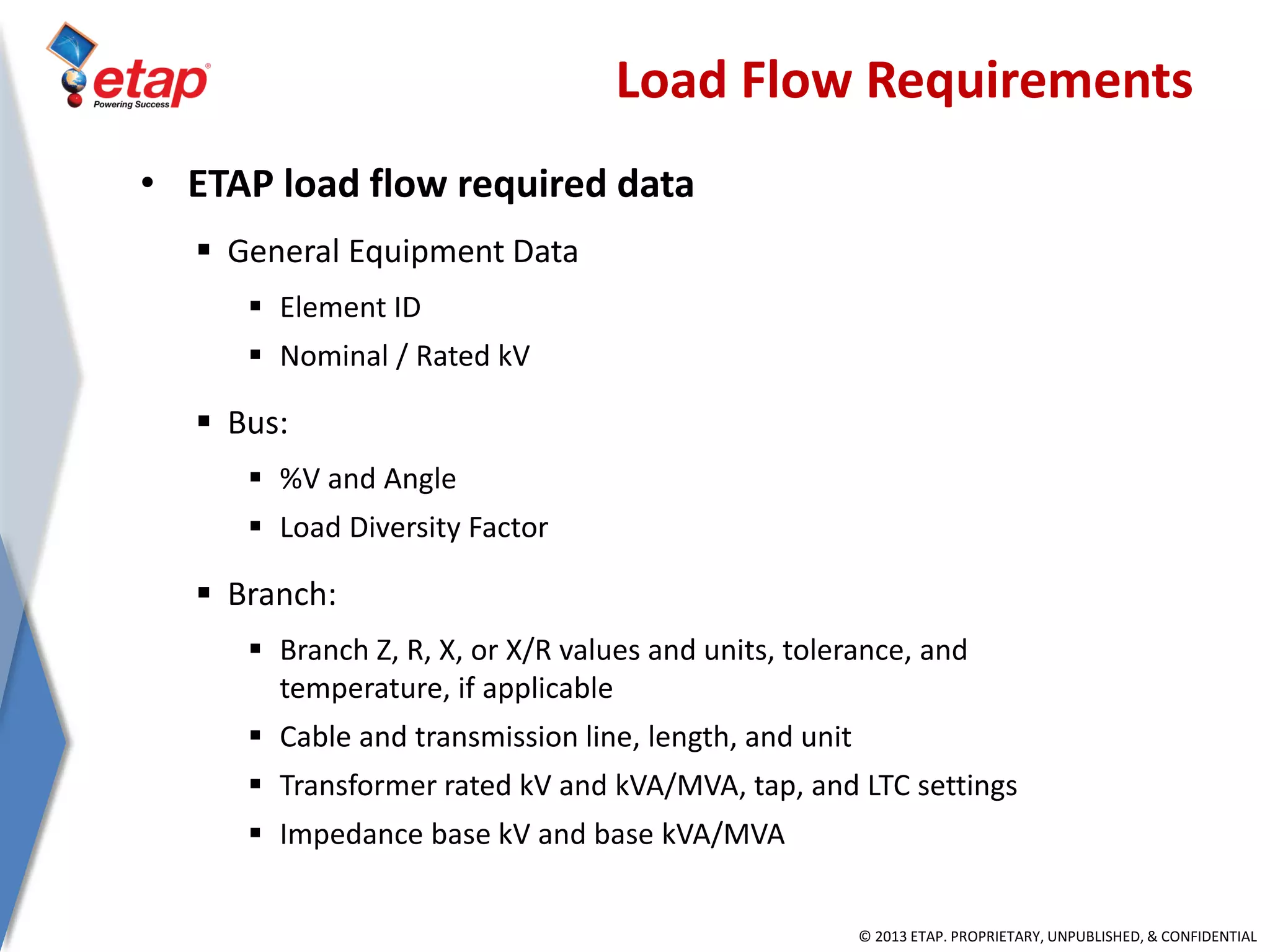
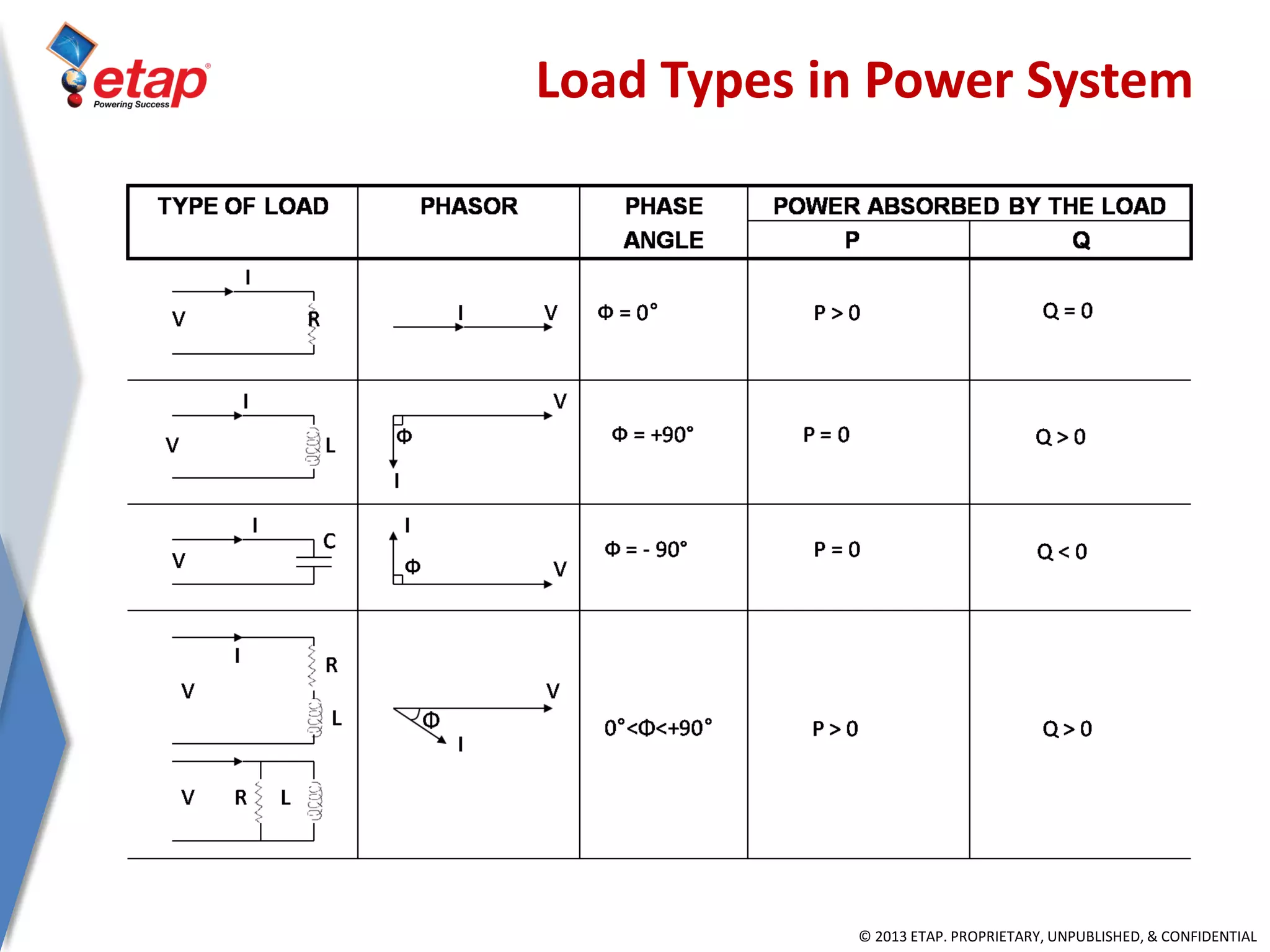
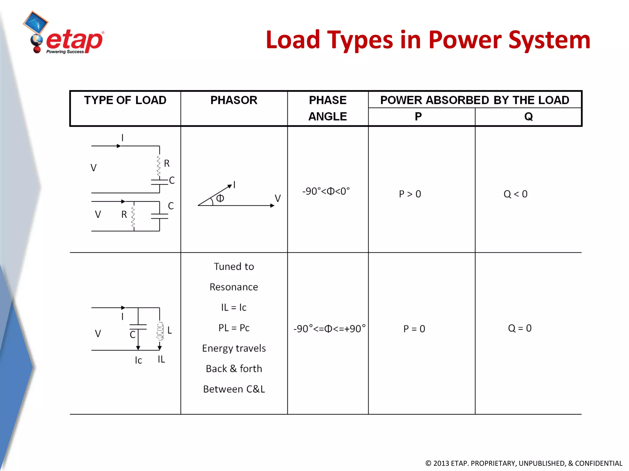
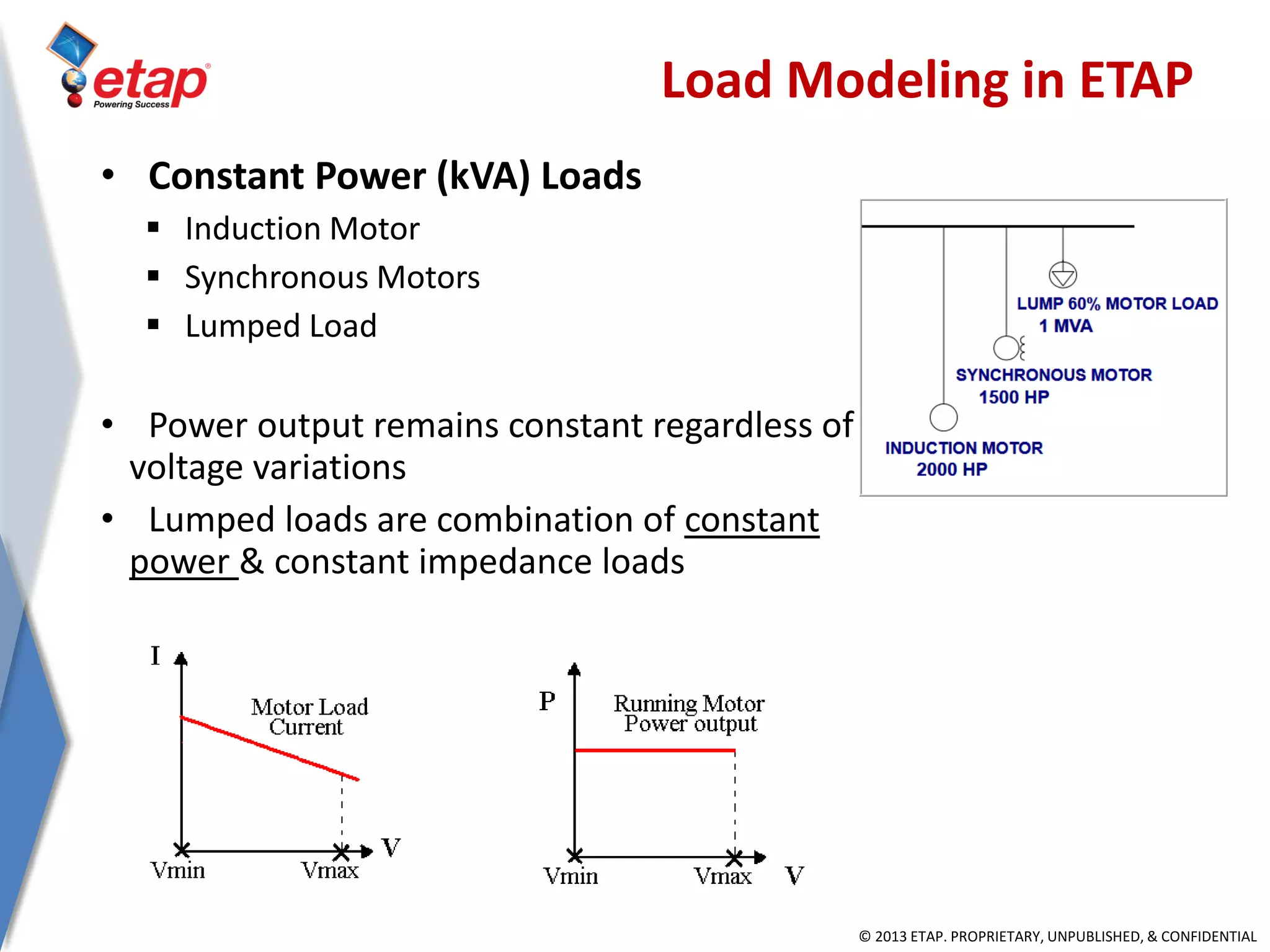
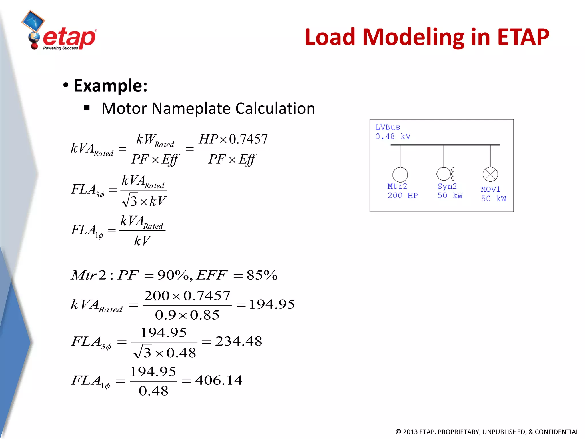
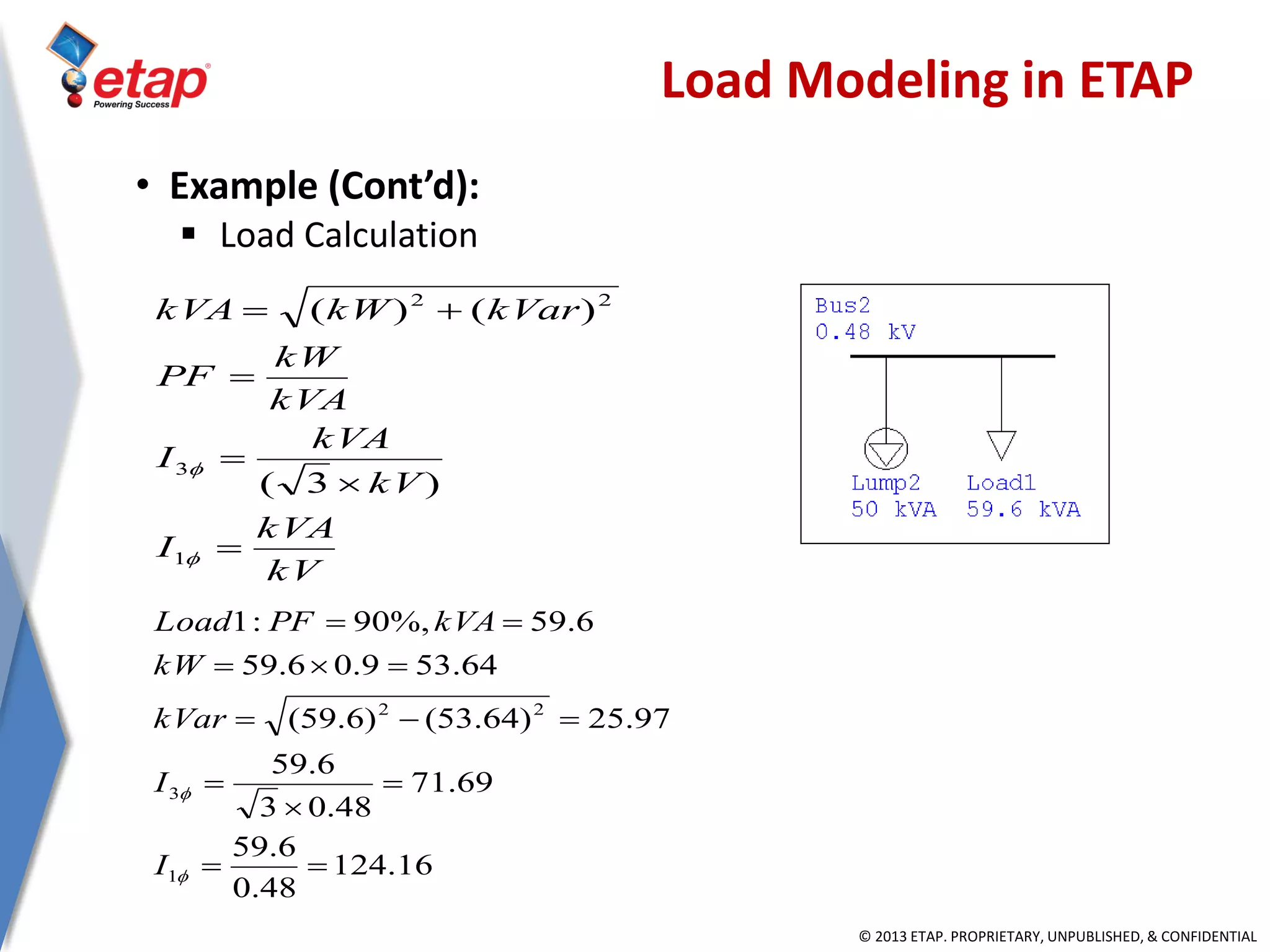
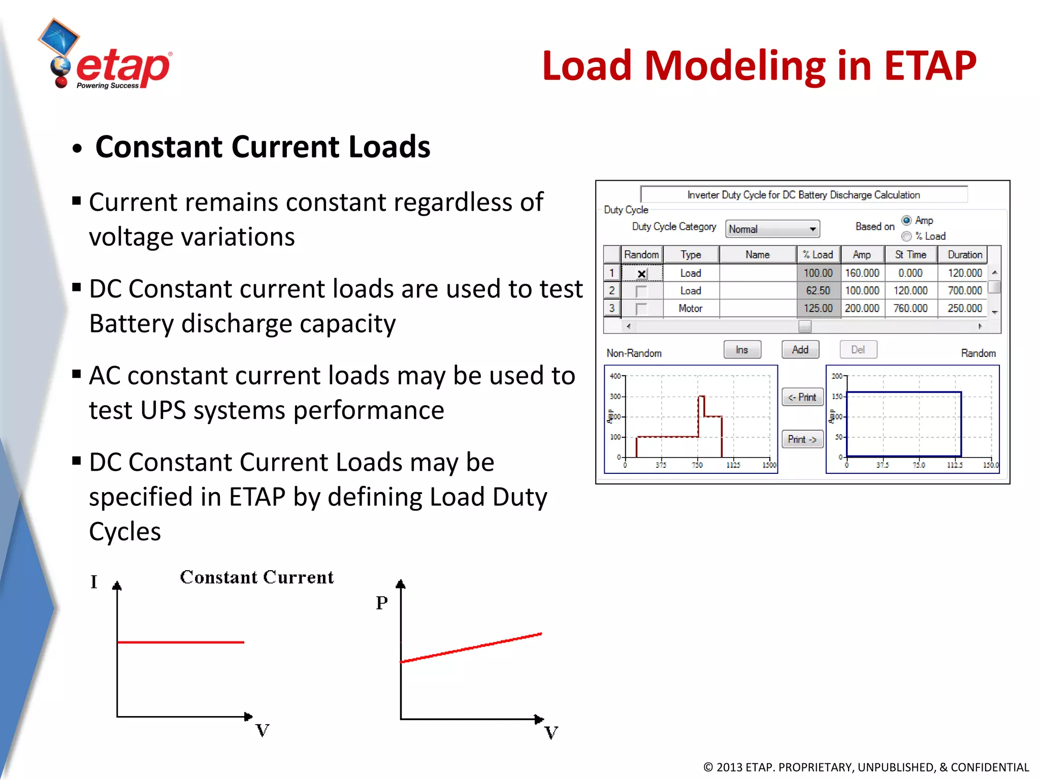
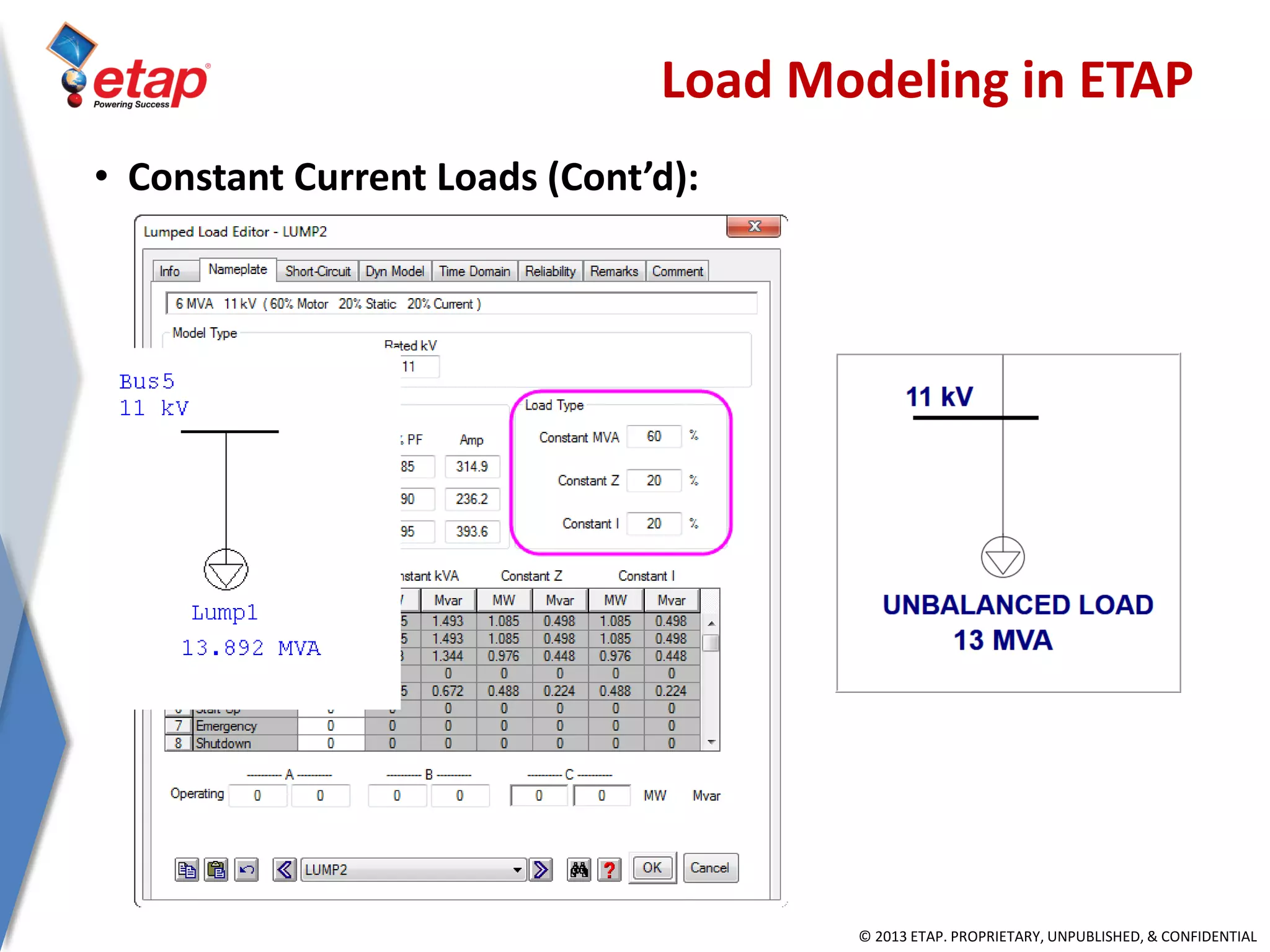
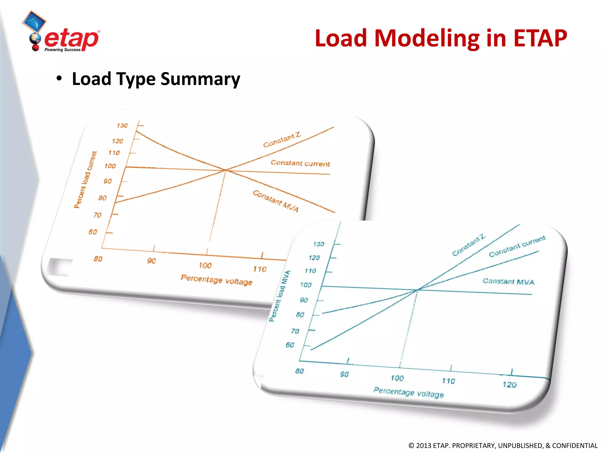
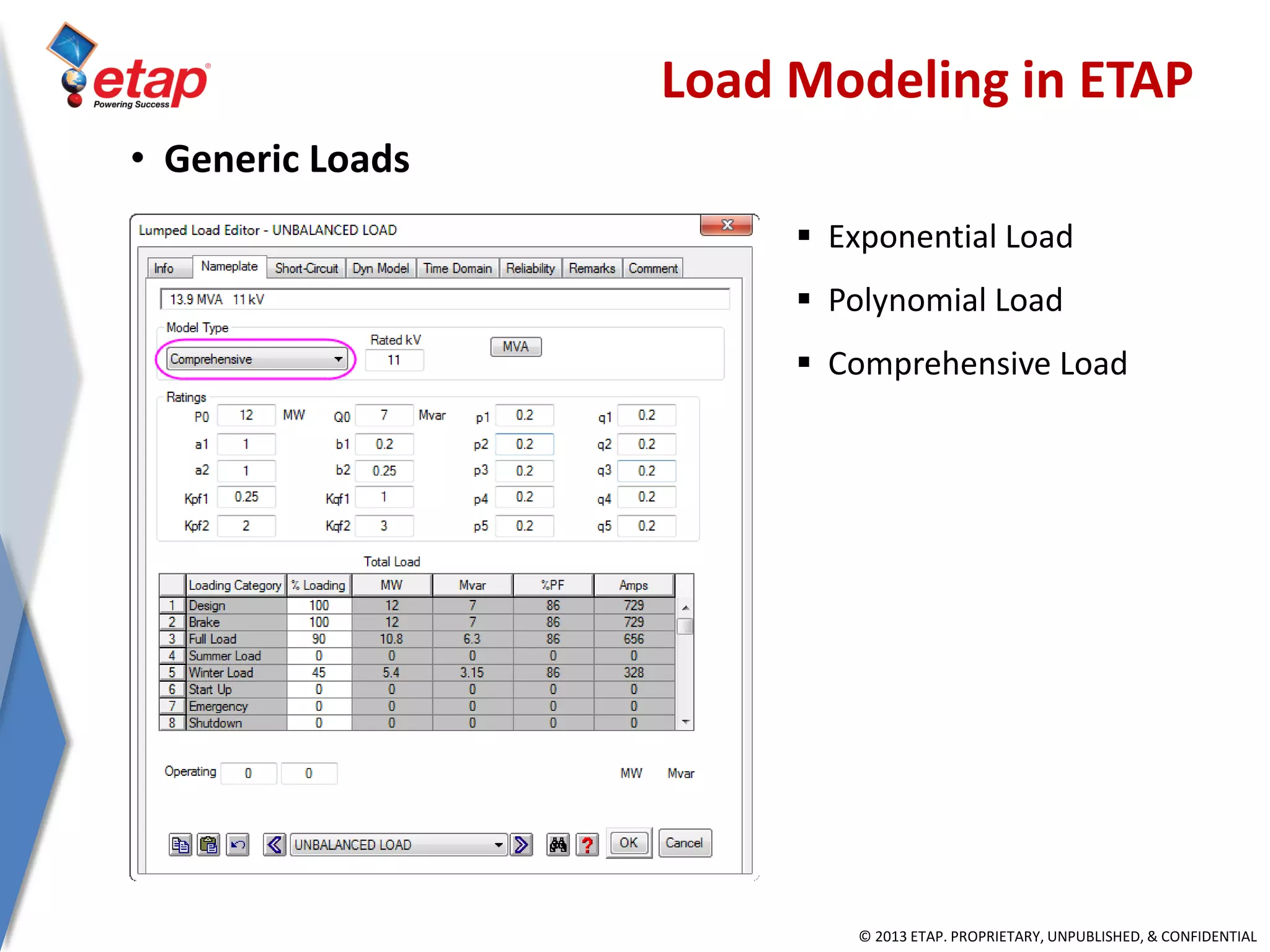
SlideShare a Scribd company logo
© 2013 ETAP. PROPRIETARY, UNPUBLISHED, & CONFIDENTIAL
Load Flow Analysis
January 2014
© 2013 ETAP. PROPRIETARY, UNPUBLISHED, & CONFIDENTIAL
Outline
• Load Flow Concept
• Load Flow Requirements
• Load Types in Power System
• Load Modeling in ETAP
• Generator Operation Modes
• Generation Modes in ETAP
• Load Flow Toolbar
• Load Flow Study Case
• Load Flow Analyzer
• Reports
• Wizards
• Panel System
© 2013 ETAP. PROPRIETARY, UNPUBLISHED, & CONFIDENTIAL
Load Flow Concept
• Load Flow Objectives
 Determine Steady State Operating Conditions
 Size Equipments
 Verify operation conditions based on limits
 Validation of data in steady state condition
© 2013 ETAP. PROPRIETARY, UNPUBLISHED, & CONFIDENTIAL
Load Flow Concept
• Determine Steady State Operating Conditions
 Voltage Profile
 Power Flows
 Current Flows
 Power Factors
 Voltage Drops
 Generator’s Mvar Demand (Qmax & Qmin)
 Generator’s MW Demand
 Total Generation & Demand
 MW & Mvar Losses
© 2013 ETAP. PROPRIETARY, UNPUBLISHED, & CONFIDENTIAL
Load Flow Concept
• Size Equipments & Determine Parameters
 Cable
 Capacitor
 Transformer MVA Capacity
 Transformer Tap Setting
 Current Limiting Reactor Ratings
 MCC & Switchgear Current Ratings
 Generator Operating Mode (Isochronous / Droop)
 Generator’s Mvar Demand
 Transmission, Distribution & Utilization kV
© 2013 ETAP. PROPRIETARY, UNPUBLISHED, & CONFIDENTIAL
Load Flow Concept
• Verify operation conditions within limits
 Bus Voltages are Within Acceptable Limits
 Voltages are Within Rated Insulation Limits of Equipment
 Power & Current Flows Do Not Exceed the Maximum Ratings
 Acceptable System MW & Mvar Losses
 Circulating Mvar Flows are Eliminated
 Steady State Stability Limits
© 2013 ETAP. PROPRIETARY, UNPUBLISHED, & CONFIDENTIAL
Load Flow Concept
• Validation of data in steady state condition
 Comparison of real time metered data with load flow results
© 2013 ETAP. PROPRIETARY, UNPUBLISHED, & CONFIDENTIAL
Load Flow Concept
• Load Flow Problem
 Given:
 Power consumption at all buses
 Branch impedances in the network
 Network Topology (Configuration)
 Power production for each generator
 Output:
 Voltage magnitude and angle at all buses
 Power flows on all the branches including power factors
 Losses on all branches
© 2013 ETAP. PROPRIETARY, UNPUBLISHED, & CONFIDENTIAL
• Non-Linear System
• Calculation Process
 Iterative Calculation
 Assume Load Voltage “VR”
(Initial Conditions)
 Calculate the Current “I”
 Based on Current
Calculate Voltage Drop “Vd”
 Re-Calculate Load Voltage “VR”
 Re-use “VR” until results are within the specified precision
Assume VR
Calc: I = Sload / VR
Calc: Vd = I * Z
Re-Calc VR = Vs - Vd
Load Flow Concept
© 2013 ETAP. PROPRIETARY, UNPUBLISHED, & CONFIDENTIAL
• Load Flow Calculation Methods
 Newton-Raphson
 Fast in speed, but high requirement on initial values
 First order derivative is used to speed up calculation
Load Flow Concept
© 2013 ETAP. PROPRIETARY, UNPUBLISHED, & CONFIDENTIAL
• Load Flow Calculation Methods
 Adaptive Newton-Raphson
 Fast in speed, but high requirement on initial values
 First order derivative is used to speed up calculation
Load Flow Concept
© 2013 ETAP. PROPRIETARY, UNPUBLISHED, & CONFIDENTIAL
• Load Flow Calculation Methods
 Accelerated Gauss-Seidel Method
 Low Requirements on initial values
 Slow in speed
Load Flow Concept
© 2013 ETAP. PROPRIETARY, UNPUBLISHED, & CONFIDENTIAL
• Load Flow Calculation Methods
 Fast-Decoupled Method
 Two sets of iteration equations: real power – voltage angle,
reactive power – voltage magnitude in speed, but high
requirement on initial values
 Fast in speed, but low in solution precision
 Better for radial systems and systems with long lines
Load Flow Concept
© 2013 ETAP. PROPRIETARY, UNPUBLISHED, & CONFIDENTIAL
Load Flow Concept
• Power in Balanced 3-Phase Systems
 Inductive loads have lagging Power Factors.
 Capacitive loads have leading Power Factors.
jQP
IV
SS
IVS
LL
LN




*
13
*
1
3
3 

Lagging Power Factor Leading Power Factor Current and Voltage
© 2013 ETAP. PROPRIETARY, UNPUBLISHED, & CONFIDENTIAL
• Leading & Lagging Power Factors
 ETAP displays power factor in %
 Leading power factor as negative
 Lagging power factor as positive
Leading
Power
Factor
Lagging
Power
Factor
P - jQ P + jQ
Load Flow Concept
© 2013 ETAP. PROPRIETARY, UNPUBLISHED, & CONFIDENTIAL
• 3-Phase Per Unit System
 Three phase power equation
 Base calculations
 Per unit calculations
B
2
B
B
B
B
B
MVA
)kV(
Z
kV3
kVA
I


B
actual
pu
B
actual
pu
Z
Z
Z
I
I
I


B
actual
pu
B
actual
pu
S
S
S
V
V
V












ZIV
VIS
3
3
Load Flow Concept












 o
B
n
B
n
B
o
Bo
pu
n
pu
S
S
V
V
ZZ
2
© 2013 ETAP. PROPRIETARY, UNPUBLISHED, & CONFIDENTIAL
• In ETAP:
 The base rating is SB = 100 MVA
 Base voltage at any point of the system is determined in respect
to the turn ratios of transformers
 To determine base voltage:
 Impedance of transformer in per unit:
Load Flow Concept
2
2
11
BB kV
N
N
kV 
1
BkV
2
BkV
2
pu
pu
R
X
1
R
X
Z
X
















R
X
x
R
pu
pu
© 2013 ETAP. PROPRIETARY, UNPUBLISHED, & CONFIDENTIAL
• Example:
 Base voltage calculation across a transformer in ETAP:
 Branch impedances in LF report are in percentage
 Turn ratio: N1/N2 = 3.31
 X/R = 12.14
Load Flow Concept
© 2013 ETAP. PROPRIETARY, UNPUBLISHED, & CONFIDENTIAL
• Example (cont’d):
 Impedance conversion to 11 MVA base
 “n” stands for new & “O” stands for old values
 The base voltage of the branch impedance (Z1) determined by
transformer turn ratio
06478.0
)14.12(1
)14.12(065.0
X
2pu 

 005336.0
14.12
06478.0
Rpu 
)3538.11115.0(
5
100
5.13
8.13
)06478.01033.5(
2
3
2
jj
S
S
V
V
ZZ o
B
n
B
n
B
o
Bo
pu
n
pu 























 
38.135j15.11Z100Z% pu 
0695.4
31.3
5.13
2N
1N
kV
V
utility
B 




 165608.0
100
)0695.4(
MVA
V
Z
22
B
B 
Load Flow Concept
© 2013 ETAP. PROPRIETARY, UNPUBLISHED, & CONFIDENTIAL
8.603j38.60Z100Z% pu 
)0382.6j6038.0(
1656.0
)1j1.0(
Z
Z
Z
B
actual
pu 


Load Flow Concept
• Example (cont’d) :
 Load flow report generated by ETAP for branches:
© 2013 ETAP. PROPRIETARY, UNPUBLISHED, & CONFIDENTIAL
Load Flow Concept
• Exercise-A1
© 2013 ETAP. PROPRIETARY, UNPUBLISHED, & CONFIDENTIAL
Load Flow Requirements
• Load Flow Overview
• Load Flow Requirements
• Load Types in Power System
• Load Modeling in ETAP
• Generator Operation Modes
• Generation Modes in ETAP
• Load Flow Toolbar
• Load Flow Study Case
• Load Flow Analyzer
• Reports
• Wizards
• Panel System
© 2013 ETAP. PROPRIETARY, UNPUBLISHED, & CONFIDENTIAL
Load Flow Requirements
• ETAP load flow required data
 General Equipment Data
 Element ID
 Nominal / Rated kV
 Bus:
 %V and Angle
 Load Diversity Factor
 Branch:
 Branch Z, R, X, or X/R values and units, tolerance, and
temperature, if applicable
 Cable and transmission line, length, and unit
 Transformer rated kV and kVA/MVA, tap, and LTC settings
 Impedance base kV and base kVA/MVA
© 2013 ETAP. PROPRIETARY, UNPUBLISHED, & CONFIDENTIAL
Load Types in Power System
• Load Flow Overview
• Load Flow Requirements
• Load Types in Power System
• Load Modeling in ETAP
• Generator Operation Modes
• Generation Modes in ETAP
• Load Flow Toolbar
• Load Flow Study Case
• Load Flow Analyzer
• Reports
• Wizards
• Panel System
© 2013 ETAP. PROPRIETARY, UNPUBLISHED, & CONFIDENTIAL
Load Types in Power System
© 2013 ETAP. PROPRIETARY, UNPUBLISHED, & CONFIDENTIAL
Load Types in Power System
© 2013 ETAP. PROPRIETARY, UNPUBLISHED, & CONFIDENTIAL
Load Modeling in ETAP
• Load Flow Overview
• Load Flow Requirements
• Load Types in Power System
• Load Modeling in ETAP
• Generator Operation Modes
• Generation Modes in ETAP
• Load Flow Toolbar
• Load Flow Study Case
• Load Flow Analyzer
• Reports
• Wizards
• Panel System
© 2013 ETAP. PROPRIETARY, UNPUBLISHED, & CONFIDENTIAL
• Constant Power (kVA) Loads
 Induction Motor
 Synchronous Motors
 Lumped Load
• Power output remains constant regardless of
voltage variations
• Lumped loads are combination of constant
power & constant impedance loads
Load Modeling in ETAP
© 2013 ETAP. PROPRIETARY, UNPUBLISHED, & CONFIDENTIAL
• Constant Impedance Loads
 Static Load
 Motor Operated Valve
 Lumped Load
 Capacitor
 Harmonic Filter
• Power & Voltage relation:
• In Load Flow Harmonic Filters may be used as capacitive
loads for Power Factor Correction.
• MOVs are modeled as constant impedance loads because
of their operating characteristics.
© 1996-2008 Operation Technology, Inc. – Workshop Notes: Load Flow Analysis Slide 31
Load Modeling in ETAP
2
VP 
© 2013 ETAP. PROPRIETARY, UNPUBLISHED, & CONFIDENTIAL
kV
kVA
FLA
kV
kVA
FLA
EffPF
HP
EffPF
kW
kVA
Rated
Rated
Rated
Rated










1
3
3
7457.0
14.406
48.0
95.194
48.234
48.03
95.194
95.194
85.09.0
7457.0200
%85%,90:2
1
3











FLA
FLA
kVA
EFFPFMtr
Rated
Load Modeling in ETAP
• Example:
 Motor Nameplate Calculation
© 2013 ETAP. PROPRIETARY, UNPUBLISHED, & CONFIDENTIAL
kV
kVA
I
kV
kVA
I
kVA
kW
PF
kVarkWkVA







1
3
22
)3(
)()(
Load Modeling in ETAP
• Example (Cont’d):
 Load Calculation
16.124
48.0
6.59
69.71
48.03
6.59
97.25)64.53()6.59(
64.539.06.59
6.59%,90:1
1
3
22









I
I
kVar
kW
kVAPFLoad
© 2013 ETAP. PROPRIETARY, UNPUBLISHED, & CONFIDENTIAL
• Constant Current Loads
 Current remains constant regardless of
voltage variations
 DC Constant current loads are used to test
Battery discharge capacity
 AC constant current loads may be used to
test UPS systems performance
 DC Constant Current Loads may be
specified in ETAP by defining Load Duty
Cycles
Load Modeling in ETAP
© 2013 ETAP. PROPRIETARY, UNPUBLISHED, & CONFIDENTIAL
Load Modeling in ETAP
• Constant Current Loads (Cont’d):
© 2013 ETAP. PROPRIETARY, UNPUBLISHED, & CONFIDENTIAL
Load Modeling in ETAP
• Load Type Summary
© 2013 ETAP. PROPRIETARY, UNPUBLISHED, & CONFIDENTIAL
 Exponential Load
 Polynomial Load
 Comprehensive Load
Load Modeling in ETAP
• Generic Loads
© 2013 ETAP. PROPRIETARY, UNPUBLISHED, & CONFIDENTIAL
Generator Operation Modes
• Load Flow Overview
• Load Flow Requirements
• Load Types in Power System
• Load Modeling in ETAP
• Generator Operation Modes
• Generation Modes in ETAP
• Load Flow Toolbar
• Load Flow Study Case
• Load Flow Analyzer
• Reports
• Wizards
• Panel System
© 2013 ETAP. PROPRIETARY, UNPUBLISHED, & CONFIDENTIAL
• Synchronous Generator & Control System
Generator Operation Modes
© 2013 ETAP. PROPRIETARY, UNPUBLISHED, & CONFIDENTIAL
• Generator Excitation System
 AVR: automatic voltage regulation
 Feedback voltage from generator terminal
 Comparison of feedback to reference
voltage in AVR unit
 Fixed: fixed excitation (no AVR)
Generator Operation Modes
© 2013 ETAP. PROPRIETARY, UNPUBLISHED, & CONFIDENTIAL
• Governor Operating Modes
 Isochronous:
 This governor setting allows the generator’s power output to be
adjusted based on the system demand
 Frequency (speed) is constant per system’s nominal frequency
 Droop:
 This governor setting allows the generator to be Base Loaded, meaning
that the MW output is fixed at
Generator Operation Modes
© 2013 ETAP. PROPRIETARY, UNPUBLISHED, & CONFIDENTIAL
• Isochronous Mode
Generator Operation Modes
© 2013 ETAP. PROPRIETARY, UNPUBLISHED, & CONFIDENTIAL
• Droop Mode
Generator Operation Modes
Loading
@60Hz
Governor
Set Point
0% A
25% B
50% C
75% D
100% E
© 2013 ETAP. PROPRIETARY, UNPUBLISHED, & CONFIDENTIAL
Generator Operation Modes
• Droop Mode – Equal Settings
 60Hz and constant loading of
400MW
 Equal load sharing
G1 = G2 = 200MW
• Droop Mode – Unequal Settings
 Increase G1 governor setting by
0.3Hz
 G2 governor setting must
decrease by 0.3Hz
 Unequal load sharing
G1 = 150 MW; G2 = 250MW
© 2013 ETAP. PROPRIETARY, UNPUBLISHED, & CONFIDENTIAL
Generator Operation Modes
• Unequal Speed Droops
 Initial operating frequency at
60Hz
 Initial loading G1 = G2 = 350MW
• Effect of load variations
 Total increase of load by
350MW
 Frequency drop by 0.5Hz
 Unequal load sharing
G1 = 600MW; G2 = 450MW
© 2013 ETAP. PROPRIETARY, UNPUBLISHED, & CONFIDENTIAL
Generator Modes in ETAP
• Load Flow Overview
• Load Flow Requirements
• Load Types in Power System
• Load Modeling in ETAP
• Generator Operation Modes
• Generation Modes in ETAP
• Load Flow Toolbar
• Load Flow Study Case
• Load Flow Analyzer
• Reports
• Wizards
• Panel System
© 2013 ETAP. PROPRIETARY, UNPUBLISHED, & CONFIDENTIAL
 Swing Mode
 Governor in Isochronous mode
 Automatic Voltage Regulator
 Voltage Control
 Governor in Droop Mode
 Automatic Voltage Regulator
 Mvar Control
 Governor in Droop Mode
 Fixed Field Excitation (no AVR action)
 PF Control
 Governor in Droop Mode
 AVR Adjusts to Power Factor Setting
• Generator/Power Grid operating modes used in LF calculation
Generator Modes in ETAP
© 2013 ETAP. PROPRIETARY, UNPUBLISHED, & CONFIDENTIAL
• If in Voltage Control Mode, the limits of P & Q are
reached, the model is changed to a constant P & Q
load
Generator Modes in ETAP
Operating
Modes
Generator Characteristics
Exciter Governor
P Q V δ°
Swing X X √ √ AVR Isoch
Voltage
Control √ X √ X AVR Droop
Mvar (PF)
Control √ √ X X Fixed Droop
© 2013 ETAP. PROPRIETARY, UNPUBLISHED, & CONFIDENTIAL
• Generator Capability
Curve
Generator Modes in ETAP
Q (Mvar)
P (MW)
Rated Operating
Point
S2=P2+Q2
A
B
D
C
Motoring Generating
Lagging
Leading
No AVR
Fast AVR
© 2013 ETAP. PROPRIETARY, UNPUBLISHED, & CONFIDENTIAL
Field Winding Heating Limit
Armature Winding Heating Limit
Machine Rating (Power Factor Point)
Steady State Stability Curve
• Maximum and Minimum Reactive Power
Generator Modes in ETAP
© 2013 ETAP. PROPRIETARY, UNPUBLISHED, & CONFIDENTIAL
Generator Operation Modes
• Adjusting Steam Flow & Excitation Current
© 2013 ETAP. PROPRIETARY, UNPUBLISHED, & CONFIDENTIAL
Field Winding
Heating Limit
Machine Rating
(Power Factor Point)
Steady State Stability Curve
• Generator Capability Curve
Generator Modes in ETAP
© 2013 ETAP. PROPRIETARY, UNPUBLISHED, & CONFIDENTIAL
• Generator Capability Curve
Load Flow Loading Page
10 Different Generation
Categories for Every
Generator or Power
Grid in the System
Generator Modes in ETAP
© 2013 ETAP. PROPRIETARY, UNPUBLISHED, & CONFIDENTIAL
X
V
)*COS(
X
*VV
Q
)(*SIN
X
*VV
P
X
V
)(*COS
X
*VV
j)(*SIN
X
*VV
jQPI*VS
2
2
21
21
21
21
2
2
21
21
21
21























222
111
VV
VV


Power Flow
© 2013 ETAP. PROPRIETARY, UNPUBLISHED, & CONFIDENTIAL
Example: Two voltage sources designated as V1 and V2 are
connected as shown. If V1= 100 /0° , V2 = 100 /30° and X = 0 +j5
determine the power flow in the system.
I
var536535.10X|I|
268j1000)68.2j10)(50j6.86(IV
268j1000)68.2j10(100IV
68.2j10I
5j
)50j6.86(0j100
X
VV
I
22
*
2
*
1
21








© 2013 ETAP. PROPRIETARY, UNPUBLISHED, & CONFIDENTIAL
2
1
0
1
Real Power Flow
Reactive Power Flow
Power Flow
1
2
V E( )
X
sin   
V E( )
X
cos   
V
2
X

0  
The following graph shows the power flow from Machine M2. This
machine behaves as a generator supplying real power and
absorbing reactive power from machine M1.
S
e power does not seem
t. Both generators are
eactive power to the
© 2013 ETAP. PROPRIETARY, UNPUBLISHED, & CONFIDENTIAL
Reports
• Load Flow Overview
• Load Flow Requirements
• Load Types in Power System
• Load Modeling in ETAP
• Generator Operation Modes
• Generation Modes in ETAP
• Load Flow Toolbar
• Load Flow Study Case
• Load Flow Analyzer
• Reports
• Wizards
• Panel System
© 2013 ETAP. PROPRIETARY, UNPUBLISHED, & CONFIDENTIAL
• Bus Voltage
ETAP displays bus voltage values in two ways
₋ kV value
₋ Percent of Nominal Bus kV
%83.97100%
5.13
min


alNo
Calculated
Calculated
kV
kV
V
kV 8.13min alNokV
%85.96100%
03.4
min


alNo
Calculated
Calculated
kV
kV
V
kV 16.4min alNokV
For Bus4:
For Bus5:
Reports
© 2013 ETAP. PROPRIETARY, UNPUBLISHED, & CONFIDENTIAL
Reports
© 2013 ETAP. PROPRIETARY, UNPUBLISHED, & CONFIDENTIAL
Reports
• Lump Load Negative Loading
© 2013 ETAP. PROPRIETARY, UNPUBLISHED, & CONFIDENTIAL
• Open LF-Example-A1
• Follow instructions in LF-Example-A1.PDF
Exercise
© 2013 ETAP. PROPRIETARY, UNPUBLISHED, & CONFIDENTIAL
Load Flow Study Case
• Load Flow Overview
• Load Flow Requirements
• Load Types in Power System
• Load Modeling in ETAP
• Generator Operation Modes
• Generation Modes in ETAP
• Load Flow Toolbar
• Load Flow Study Case
• Load Flow Analyzer
• Reports
• Wizards
• Panel System
© 2013 ETAP. PROPRIETARY, UNPUBLISHED, & CONFIDENTIAL
• Transformer Impedance
– Adjust transformer impedance based on possible length variation tolerance
• Reactor Impedance
– Adjust reactor impedance based on specified tolerance
• Overload Heater
– Adjust Overload Heater resistance based on specified tolerance
• Transmission Line Length
– Adjust Transmission Line Impedance based on possible length variation
tolerance
• Cable Length
– Adjust Cable Impedance based on possible length variation tolerance
Load Flow Study Case
© 2013 ETAP. PROPRIETARY, UNPUBLISHED, & CONFIDENTIAL
Adjustments applied
•Individual
•Global
Temperature Correction
• Cable Resistance
• Transmission Line
Resistance
Load Flow Study Case
© 2013 ETAP. PROPRIETARY, UNPUBLISHED, & CONFIDENTIAL
Allowable Voltage Drop
NEC and ANSI C84.1
© 2013 ETAP. PROPRIETARY, UNPUBLISHED, & CONFIDENTIAL
Load Flow Study Case
• Load Flow Alerts
© 2013 ETAP. PROPRIETARY, UNPUBLISHED, & CONFIDENTIAL
Bus Alerts Monitor Continuous Amps
Cable Monitor Continuous Amps
Reactor Monitor Continuous Amps
Line Monitor Line Ampacity
Transformer Monitor Maximum MVA Output
UPS/Panel Monitor Panel Continuous Amps
Generator Monitor Generator Rated MW
Load Flow Study Case
• Load Flow Alerts
© 2013 ETAP. PROPRIETARY, UNPUBLISHED, & CONFIDENTIAL
Protective Devices Monitored parameters % Condition reported
Low Voltage Circuit Breaker Continuous rated Current OverLoad
High Voltage Circuit Breaker Continuous rated Current OverLoad
Fuses Rated Current OverLoad
Contactors Continuous rated Current OverLoad
SPDT / SPST switches Continuous rated Current OverLoad
• Protective Device Alerts
Load Flow Study Case
© 2013 ETAP. PROPRIETARY, UNPUBLISHED, & CONFIDENTIAL
If the Auto Display feature is
active, the Alert View Window
will appear as soon as the
Load Flow calculation has
finished.
© 1996-2009 Operation Technology, Inc. – Workshop Notes: Load Flow Analysis Slide 69
Load Flow Study Case
© 2013 ETAP. PROPRIETARY, UNPUBLISHED, & CONFIDENTIAL
• Open LF-Example-B1
• Follow instructions in LF-Example-B1.PDF
Exercise
© 2013 ETAP. PROPRIETARY, UNPUBLISHED, & CONFIDENTIAL
• Load Flow Example B1
Part 1
© 1996-2009 Operation Technology, Inc. - Workshop Notes: Load Flow Analysis
Slide 71
Exercise
© 2013 ETAP. PROPRIETARY, UNPUBLISHED, & CONFIDENTIAL
• Load Flow Example B1 Part 2
Exercise
© 2013 ETAP. PROPRIETARY, UNPUBLISHED, & CONFIDENTIAL
• Under/Over Voltage Conditions must be fixed for proper
equipment operation and insulation ratings be met.
• Methods of Improving Voltage Conditions:
– Transformer Replacement
– Capacitor Addition
– Transformer Tap Adjustment
Exercise
© 2013 ETAP. PROPRIETARY, UNPUBLISHED, & CONFIDENTIAL
• Create Under Voltage
Condition
– Change Syn2 Quantity to 6.
(Info Page, Quantity Field)
– Run LF
– Bus8 Turns Magenta (Under
Voltage Condition)
• Method 1 - Change Xfmr
– Change T4 from 3 MVA to 8
MVA, will notice slight
improvement on the Bus8 kV
– Too Expensive and time
consuming
• Method 2 - Shunt Capacitor
– Add Shunt Capacitor to Bus8
– 300 kvar 3 Banks
– Voltage is improved
• Method 3 - Change Tap
– Place LTC on Primary of T6
– Select Bus8 for Control Bus
– Select Update LTC in the Study
Case
– Run LF
– Bus Voltage Comes within
specified limits
Exercise
© 2013 ETAP. PROPRIETARY, UNPUBLISHED, & CONFIDENTIAL
• Vars from Utility
– Add Switch to CAP1
– Open Switch
– Run LF
• Method 1 – Generator
– Change Generator from
Voltage Control to Mvar
Control
– Set Mvar Design Setting to 5
Mvars
• Method 2 – Add Capacitor
– Close Switch
– Run Load Flow
– Var Contribution from the
Utility reduces
• Method 3 – Xfmr MVA
– Change T1 Mva to 40 MVA
– Will notice decrease in the
contribution from the Utility
• MVAR Control
Exercise
© 2013 ETAP. PROPRIETARY, UNPUBLISHED, & CONFIDENTIAL
• Negative Impedance
• Zero or Very Small Impedance
• Widely Different Branch Impedance Values
• Long Radial System Configurations
• Bad Bus Voltage Initial Values
• Load Flow Convergence
Exercise
© 2013 ETAP. PROPRIETARY, UNPUBLISHED, & CONFIDENTIAL
• Open LF-Example-A2
• Follow instructions in LF-Example-A2.PDF
Exercise
© 2013 ETAP. PROPRIETARY, UNPUBLISHED, & CONFIDENTIAL
Advanced LF Topics
Voltage Control
Mvar Control
Load Flow Convergence
Load Flow vs. Optimal Power Flow
© 2013 ETAP. PROPRIETARY, UNPUBLISHED, & CONFIDENTIAL
• Review of Load Flow Study
– Given generation, loading and control settings (Mwgen, Vgen, LTC,
Capacitor Bank, …)
– Solve bus voltages and branch flows
– Check over/under voltage, device overloading conditions
– Reset controls and run Load Flow again
– Iterative process
Advanced Topics
© 2013 ETAP. PROPRIETARY, UNPUBLISHED, & CONFIDENTIAL
• Optimal Load Flow Approach
– Given control setting ranges
– Specify bus voltage and branch loading constraints
– Select optimization objectives (Min. P Losses, Min. Q Losses, …)
– Solve bus voltages, branch flows and control settings
– Direct solution
Advanced Topics
© 2013 ETAP. PROPRIETARY, UNPUBLISHED, & CONFIDENTIAL
• Control Variables
– Load Tap Changer (LTC) Settings
– Generator AVR Settings
– Generator MW Generation
– Series or Shunt VAR Compensator Settings
– Phase Shift Transformer Tap Positions
– Switched Capacitor Settings
– Load Shedding
– DC Line Flow
Advanced Topics
© 2013 ETAP. PROPRIETARY, UNPUBLISHED, & CONFIDENTIAL
Objective Function:
• Minimize Real Power Losses
- To minimize real power losses in the system
• Minimize Reactive Power Losses
- To minimize reactive power losses in the system
• Minimize Swing Bus Power
- To minimize real power generation at the swing bus(s)
Advanced Topics
© 2013 ETAP. PROPRIETARY, UNPUBLISHED, & CONFIDENTIAL
• Minimize Shunt var Devices
- To minimize var generation from available shunt var control devices
• Minimize Fuel Cost
- To minimize total generation fuel cost
• Minimize Series Compensation
- To minimize var generation from available series var control devices
Advanced Topics
© 2013 ETAP. PROPRIETARY, UNPUBLISHED, & CONFIDENTIAL
• Minimize Load Shedding
- To minimize load to be shed from the available bus load shed schedule
• Minimize Control Movement
- To minimize total number of controls
• Minimize Control Adjustment
- To minimize overall adjustment from all controls
Advanced Topics
© 2013 ETAP. PROPRIETARY, UNPUBLISHED, & CONFIDENTIAL
• Maximize Voltage Security Index
Where,
 




 

AllBuses
i
n
i
avgii
dV
VV
2
,
IndexSecurityVoltage
2
min,max,
,
ii
avgi
VV
V


2
min,max, ii
i
VV
dV


Advanced Topics
© 2013 ETAP. PROPRIETARY, UNPUBLISHED, & CONFIDENTIAL
• Maximize Line Flow Security Index
Where, is the line rating
• Flat Voltage Profile
- Voltage Magnitude difference between all buses is minimum
 






sAllBranche
i
n
i
i
S
S
2
IndexSecurityFlowLine
iSd
Advanced Topics
© 2013 ETAP. PROPRIETARY, UNPUBLISHED, & CONFIDENTIAL
Constraints:
• Bus Voltage Constraints
• Branch Flow Constraints
• Interface Flow Constraints
Advanced Topics
© 2013 ETAP. PROPRIETARY, UNPUBLISHED, & CONFIDENTIAL
• Open LF-Example-A3
• Follow instructions in LF-Example-A3.PDF
Exercise
© 2013 ETAP. PROPRIETARY, UNPUBLISHED, & CONFIDENTIAL
Exercise
• Comparison of LF and OPF:
© 2013 ETAP. PROPRIETARY, UNPUBLISHED, & CONFIDENTIAL
Panel System
• Load Flow Overview
• Load Flow Requirements
• Load Types in Power System
• Load Modeling in ETAP
• Generator Operation Modes
• Generation Modes in ETAP
• Load Flow Toolbar
• Load Flow Study Case
• Load Flow Analyzer
• Reports
• Wizards
• Panel System
© 2013 ETAP. PROPRIETARY, UNPUBLISHED, & CONFIDENTIAL
Panel Systems
© 2013 ETAP. PROPRIETARY, UNPUBLISHED, & CONFIDENTIAL
Panel Boards:
• They are a collection of branch circuits feeding system loads
• Panel System is used for representing power and lighting panels
in electrical systems
Click to drop once on OLV
Double-Click to drop multiple panels
Panel System
© 2013 ETAP. PROPRIETARY, UNPUBLISHED, & CONFIDENTIAL
A panel branch circuit load can be modeled as an internal or
external load
Advantages:
1. Easier Data Entry
2. Concise System
Representation
Panel System
• Representation:
© 2013 ETAP. PROPRIETARY, UNPUBLISHED, & CONFIDENTIAL
Pin 0 is the top pin of the panel
ETAP allows up to 24 external load connections
• Pin Assignment:
Panel System
© 2013 ETAP. PROPRIETARY, UNPUBLISHED, & CONFIDENTIAL
Assumptions:
• Vrated (internal load) = Vrated (Panel Voltage)
• Note that if a 1-Phase load is connected to a 3-Phase panel
circuit, the rated voltage of the panel circuit is (1/√3) times the
rated panel voltage
• The voltage of L1 or L2 phase in a 1-Phase 3-Wire panel is (1/2)
times the rated voltage of the panel
• There are no losses in the feeders connecting a load to the panel
• Static loads are calculated based on their rated voltage
Panel System
© 2013 ETAP. PROPRIETARY, UNPUBLISHED, & CONFIDENTIAL
Load Connected Between Two Phases of a
3-Phase System
A
B
C
Load
IBC
IC = -IBC
A
B
C
LoadB
IB = IBC
Angle by which load current IBC lags the load voltage = θ
Therefore, for load connected between phases B and C:
SBC = VBC.IBC
PBC = VBC.IBC.cos θ
QBC = VBC.IBC.sin θ
For load connected to phase B
SB = VB.IB
PB = VB.IB.cos (θ - 30)
QB = VB.IB.sin (θ - 30)
And, for load connected to phase C
SC = VC.IC
PC = VC.IC.cos (θ + 30)
QC = VC.IC.sin (θ + 30)
Panel System
• Line to Line Connections
© 2013 ETAP. PROPRIETARY, UNPUBLISHED, & CONFIDENTIAL
3-Phase 4-Wire Panel
3-Phase 3-Wire Panel
1-Phase 3-Wire Panel
1-Phase 2-Wire Panel
NEC Selection
A, B, C from top to bottom or
left to right from the front of the
panel
Phase B shall be the highest
voltage (LG) on a 3-phase, 4-
wire delta connected system
(midpoint grounded)
• Info Page:
Panel System
© 2013 ETAP. PROPRIETARY, UNPUBLISHED, & CONFIDENTIAL
Intelligent kV Calculation
If a 1-Phase panel is connected to a 3-Phase bus
having a nominal voltage equal to 0.48 kV, the
default rated kV of the panel is set to (0.48/1.732
=) 0.277 kV
For IEC, Enclosure Type
is Ingress Protection
(IPxy), where IP00 means
no protection or shielding
on the panel
Select ANSI or IEC
Breakers or Fuses from
Main Device Library
• Rating Page:
Panel System
© 2013 ETAP. PROPRIETARY, UNPUBLISHED, & CONFIDENTIAL
Circuit Numbers with
Column Layout
Circuit Numbers with
Standard Layout
• Schedule Page:
Panel System
© 2013 ETAP. PROPRIETARY, UNPUBLISHED, & CONFIDENTIAL
₋ First 14 load items in the list are based on NEC 1999
₋ Last 10 load types in the Panel Code Factor Table are user-defined
₋ Load Type is used to determine the Code Factors used in calculating the total panel
load
₋ External loads are classified as motor load or static load according to the element
type
₋ For External links the load status is determined from the connected load’s demand
factor status
• Pin Assignment:
Panel System
© 2013 ETAP. PROPRIETARY, UNPUBLISHED, & CONFIDENTIAL
Enter per phase VA, W, or
Amperes for this load.
For example, if total Watts
for a 3-phase load are 1200,
enter W as 400 (=1200/3)
• Rating Tab:
Panel System
© 2013 ETAP. PROPRIETARY, UNPUBLISHED, & CONFIDENTIAL
For internal loads, enter the % loading for the selected loading category
For both internal and external loads, Amp values are
calculated based on terminal bus nominal kV
• Loading Tab:
Panel System
© 2013 ETAP. PROPRIETARY, UNPUBLISHED, & CONFIDENTIAL
Library Quick Pick -
LV Circuit Breaker
(Molded Case, with
Thermal Magnetic Trip
Device) or
Library Quick Pick –
Fuse will appear
depending on the
Type of protective
device selected.
• Protective Device Tab:
Panel System
© 2013 ETAP. PROPRIETARY, UNPUBLISHED, & CONFIDENTIAL
• Feeder Tab:
Panel System
© 2013 ETAP. PROPRIETARY, UNPUBLISHED, & CONFIDENTIAL
Copy the content of the selected
row to clipboard. Circuit number,
Phase, Pole, Load Name, Link
and State are not copied.
Paste the entire content (of the
copied row) in the selected row.
This will work when the Link
Type is other than space or
unusable, and only for fields
which are not blocked.
Blank out the contents of the entire
selected row.
• Action Bottons:
Panel System
© 2013 ETAP. PROPRIETARY, UNPUBLISHED, & CONFIDENTIAL
Continuous Load – Per Phase and Total
Non-Continuous Load – Per Phase and Total
Connected Load – Per Phase and Total (Continuous + Non-Continuous Load)
Code Demand – Per Phase and Total
• Summary Page:
Panel System
© 2013 ETAP. PROPRIETARY, UNPUBLISHED, & CONFIDENTIAL
• Output Report
Panel System
© 2013 ETAP. PROPRIETARY, UNPUBLISHED, & CONFIDENTIAL
Code demand load depends on Panel Code Factors
The first fourteen have fixed formats per NEC 1999
Code demand load calculation for internal loads are done
for each types of load separately and then summed up
• Panel Code Factors
Panel System

More Related Content

What's hot

ETAP - Arc flash introduction
ETAP - Arc flash introductionETAP - Arc flash introduction
ETAP - Arc flash introduction
Himmelstern
 
ETAP - Harmonics Analysis
ETAP - Harmonics AnalysisETAP - Harmonics Analysis
ETAP - Harmonics Analysis
Himmelstern
 
ETAP - Coordination and protecion
ETAP -  Coordination and protecionETAP -  Coordination and protecion
ETAP - Coordination and protecion
Himmelstern
 
Short Circuit, Protective Device Coordination
Short Circuit, Protective Device CoordinationShort Circuit, Protective Device Coordination
Short Circuit, Protective Device Coordination
michaeljmack
 
ETAP - Transient stability
ETAP - Transient stabilityETAP - Transient stability
ETAP - Transient stability
Himmelstern
 
ETAP - 09 motor acceleration
ETAP - 09 motor accelerationETAP - 09 motor acceleration
ETAP - 09 motor acceleration
Himmelstern
 
ETAP - 09 motor-acceleration
ETAP - 09 motor-accelerationETAP - 09 motor-acceleration
ETAP - 09 motor-acceleration
Himmelstern
 
Practical handbook-for-relay-protection-engineers
Practical handbook-for-relay-protection-engineersPractical handbook-for-relay-protection-engineers
Practical handbook-for-relay-protection-engineers
SARAVANAN A
 
Loss of excitation
Loss of excitationLoss of excitation
Loss of excitation
NTPC
 
Chapter 01- High Voltage Engineering Introduction
Chapter 01- High Voltage Engineering IntroductionChapter 01- High Voltage Engineering Introduction
Chapter 01- High Voltage Engineering Introduction
MUET SZAB Campus Khairpur Mir's Sindh Pakistan
 
Generator protection calculations settings
Generator protection calculations settingsGenerator protection calculations settings
Generator protection calculations settings
michaeljmack
 
ETAP - Transformer sizing using etap
ETAP - Transformer sizing using etapETAP - Transformer sizing using etap
ETAP - Transformer sizing using etap
Himmelstern
 
System neutral-earthing
System neutral-earthingSystem neutral-earthing
System neutral-earthing
azzaabo
 
Power system interconnection presentation
Power system interconnection presentationPower system interconnection presentation
Power system interconnection presentation
Aneeque Qaiser
 
ETAP - Cable pulling
ETAP - Cable pullingETAP - Cable pulling
ETAP - Cable pulling
Himmelstern
 
Power system fault analysis ppt
Power system fault analysis pptPower system fault analysis ppt
Power system fault analysis ppt
karikalan123
 
ETAP - Ac networks
ETAP - Ac networksETAP - Ac networks
ETAP - Ac networks
Himmelstern
 
UPS (Uninterruptible Power Supply) on oil and gas industry. pdf
UPS (Uninterruptible Power Supply) on oil and gas industry. pdfUPS (Uninterruptible Power Supply) on oil and gas industry. pdf
UPS (Uninterruptible Power Supply) on oil and gas industry. pdf
lindkw
 
Fault Calculations
Fault CalculationsFault Calculations
Fault Calculations
michaeljmack
 
Transformer Differential Protection Setting Calculations
Transformer Differential Protection Setting CalculationsTransformer Differential Protection Setting Calculations
Transformer Differential Protection Setting Calculations
Power System Operation
 

What's hot (20)

ETAP - Arc flash introduction
ETAP - Arc flash introductionETAP - Arc flash introduction
ETAP - Arc flash introduction
 
ETAP - Harmonics Analysis
ETAP - Harmonics AnalysisETAP - Harmonics Analysis
ETAP - Harmonics Analysis
 
ETAP - Coordination and protecion
ETAP -  Coordination and protecionETAP -  Coordination and protecion
ETAP - Coordination and protecion
 
Short Circuit, Protective Device Coordination
Short Circuit, Protective Device CoordinationShort Circuit, Protective Device Coordination
Short Circuit, Protective Device Coordination
 
ETAP - Transient stability
ETAP - Transient stabilityETAP - Transient stability
ETAP - Transient stability
 
ETAP - 09 motor acceleration
ETAP - 09 motor accelerationETAP - 09 motor acceleration
ETAP - 09 motor acceleration
 
ETAP - 09 motor-acceleration
ETAP - 09 motor-accelerationETAP - 09 motor-acceleration
ETAP - 09 motor-acceleration
 
Practical handbook-for-relay-protection-engineers
Practical handbook-for-relay-protection-engineersPractical handbook-for-relay-protection-engineers
Practical handbook-for-relay-protection-engineers
 
Loss of excitation
Loss of excitationLoss of excitation
Loss of excitation
 
Chapter 01- High Voltage Engineering Introduction
Chapter 01- High Voltage Engineering IntroductionChapter 01- High Voltage Engineering Introduction
Chapter 01- High Voltage Engineering Introduction
 
Generator protection calculations settings
Generator protection calculations settingsGenerator protection calculations settings
Generator protection calculations settings
 
ETAP - Transformer sizing using etap
ETAP - Transformer sizing using etapETAP - Transformer sizing using etap
ETAP - Transformer sizing using etap
 
System neutral-earthing
System neutral-earthingSystem neutral-earthing
System neutral-earthing
 
Power system interconnection presentation
Power system interconnection presentationPower system interconnection presentation
Power system interconnection presentation
 
ETAP - Cable pulling
ETAP - Cable pullingETAP - Cable pulling
ETAP - Cable pulling
 
Power system fault analysis ppt
Power system fault analysis pptPower system fault analysis ppt
Power system fault analysis ppt
 
ETAP - Ac networks
ETAP - Ac networksETAP - Ac networks
ETAP - Ac networks
 
UPS (Uninterruptible Power Supply) on oil and gas industry. pdf
UPS (Uninterruptible Power Supply) on oil and gas industry. pdfUPS (Uninterruptible Power Supply) on oil and gas industry. pdf
UPS (Uninterruptible Power Supply) on oil and gas industry. pdf
 
Fault Calculations
Fault CalculationsFault Calculations
Fault Calculations
 
Transformer Differential Protection Setting Calculations
Transformer Differential Protection Setting CalculationsTransformer Differential Protection Setting Calculations
Transformer Differential Protection Setting Calculations
 

Similar to ETAP - Load flow and panel rev2014-1

LOAD_FLOW_STUDY.pptx
LOAD_FLOW_STUDY.pptxLOAD_FLOW_STUDY.pptx
LOAD_FLOW_STUDY.pptx
KittyTripathi1
 
AMSC D-VAR® Model for PSSE_releasable
AMSC D-VAR® Model for PSSE_releasableAMSC D-VAR® Model for PSSE_releasable
AMSC D-VAR® Model for PSSE_releasablejohnwrightsmith
 
Electrical power system management
Electrical power system managementElectrical power system management
Electrical power system management
Akshay Awadhani
 
Voltage Source Inverters in microgrid along with power quality improvement te...
Voltage Source Inverters in microgrid along with power quality improvement te...Voltage Source Inverters in microgrid along with power quality improvement te...
Voltage Source Inverters in microgrid along with power quality improvement te...
IRJET Journal
 
DigSILENT PF - 03 load flow analysis
DigSILENT PF - 03 load flow analysisDigSILENT PF - 03 load flow analysis
DigSILENT PF - 03 load flow analysis
Himmelstern
 
DigSILENT PF - 03 load flow_analysis
DigSILENT PF - 03 load flow_analysisDigSILENT PF - 03 load flow_analysis
DigSILENT PF - 03 load flow_analysis
Himmelstern
 
LoadModeling (1).ppt
LoadModeling (1).pptLoadModeling (1).ppt
LoadModeling (1).ppt
Godspower Bruno, GMNSE
 
LoadModeling.ppt
LoadModeling.pptLoadModeling.ppt
LoadModeling.ppt
Godspower Bruno, GMNSE
 
Configuration and working point and state estimation
Configuration and working point and state estimationConfiguration and working point and state estimation
Configuration and working point and state estimation
Daniel Obaleye
 
ETAP - csd - Control System Diagram
ETAP - csd - Control System DiagramETAP - csd - Control System Diagram
ETAP - csd - Control System Diagram
Himmelstern
 
Modeling Optimization Voltage Index Unified Power Flow Controller Equivalent ...
Modeling Optimization Voltage Index Unified Power Flow Controller Equivalent ...Modeling Optimization Voltage Index Unified Power Flow Controller Equivalent ...
Modeling Optimization Voltage Index Unified Power Flow Controller Equivalent ...
IJMTST Journal
 
10 03 Excitation System.pdf
10 03 Excitation System.pdf10 03 Excitation System.pdf
10 03 Excitation System.pdf
haythamomar7
 
ETAP - unbalanced load flow
ETAP - unbalanced load flowETAP - unbalanced load flow
ETAP - unbalanced load flow
Himmelstern
 
IRJET-Power Quality Improvement by using CHB Inverter based DVR
IRJET-Power Quality Improvement by using CHB Inverter based DVRIRJET-Power Quality Improvement by using CHB Inverter based DVR
IRJET-Power Quality Improvement by using CHB Inverter based DVR
IRJET Journal
 
Emergency generator sizing and motor starting analysis
Emergency generator sizing and motor starting analysisEmergency generator sizing and motor starting analysis
Emergency generator sizing and motor starting analysis
Himmelstern
 
Microgrid & renewable integration at burbank water & power
Microgrid & renewable integration at burbank water & powerMicrogrid & renewable integration at burbank water & power
Microgrid & renewable integration at burbank water & power
Schneider Electric
 
2014 Wind Turbine Blade Workshop- Johansen
2014 Wind Turbine Blade Workshop- Johansen2014 Wind Turbine Blade Workshop- Johansen
2014 Wind Turbine Blade Workshop- Johansen
Sandia National Laboratories: Energy & Climate: Renewables
 
4.4_Micro Grid Design_Bello_EPRI/SNL Microgrid
4.4_Micro Grid Design_Bello_EPRI/SNL Microgrid4.4_Micro Grid Design_Bello_EPRI/SNL Microgrid
4.4_Micro Grid Design_Bello_EPRI/SNL Microgrid
Sandia National Laboratories: Energy & Climate: Renewables
 
IRJET-Simulation and Modeling of Dynamic Voltage Restorer for Compensation Of...
IRJET-Simulation and Modeling of Dynamic Voltage Restorer for Compensation Of...IRJET-Simulation and Modeling of Dynamic Voltage Restorer for Compensation Of...
IRJET-Simulation and Modeling of Dynamic Voltage Restorer for Compensation Of...
IRJET Journal
 

Similar to ETAP - Load flow and panel rev2014-1 (20)

LOAD_FLOW_STUDY.pptx
LOAD_FLOW_STUDY.pptxLOAD_FLOW_STUDY.pptx
LOAD_FLOW_STUDY.pptx
 
AMSC D-VAR® Model for PSSE_releasable
AMSC D-VAR® Model for PSSE_releasableAMSC D-VAR® Model for PSSE_releasable
AMSC D-VAR® Model for PSSE_releasable
 
Electrical power system management
Electrical power system managementElectrical power system management
Electrical power system management
 
Voltage Source Inverters in microgrid along with power quality improvement te...
Voltage Source Inverters in microgrid along with power quality improvement te...Voltage Source Inverters in microgrid along with power quality improvement te...
Voltage Source Inverters in microgrid along with power quality improvement te...
 
voltage stability
voltage stabilityvoltage stability
voltage stability
 
DigSILENT PF - 03 load flow analysis
DigSILENT PF - 03 load flow analysisDigSILENT PF - 03 load flow analysis
DigSILENT PF - 03 load flow analysis
 
DigSILENT PF - 03 load flow_analysis
DigSILENT PF - 03 load flow_analysisDigSILENT PF - 03 load flow_analysis
DigSILENT PF - 03 load flow_analysis
 
LoadModeling (1).ppt
LoadModeling (1).pptLoadModeling (1).ppt
LoadModeling (1).ppt
 
LoadModeling.ppt
LoadModeling.pptLoadModeling.ppt
LoadModeling.ppt
 
Configuration and working point and state estimation
Configuration and working point and state estimationConfiguration and working point and state estimation
Configuration and working point and state estimation
 
ETAP - csd - Control System Diagram
ETAP - csd - Control System DiagramETAP - csd - Control System Diagram
ETAP - csd - Control System Diagram
 
Modeling Optimization Voltage Index Unified Power Flow Controller Equivalent ...
Modeling Optimization Voltage Index Unified Power Flow Controller Equivalent ...Modeling Optimization Voltage Index Unified Power Flow Controller Equivalent ...
Modeling Optimization Voltage Index Unified Power Flow Controller Equivalent ...
 
10 03 Excitation System.pdf
10 03 Excitation System.pdf10 03 Excitation System.pdf
10 03 Excitation System.pdf
 
ETAP - unbalanced load flow
ETAP - unbalanced load flowETAP - unbalanced load flow
ETAP - unbalanced load flow
 
IRJET-Power Quality Improvement by using CHB Inverter based DVR
IRJET-Power Quality Improvement by using CHB Inverter based DVRIRJET-Power Quality Improvement by using CHB Inverter based DVR
IRJET-Power Quality Improvement by using CHB Inverter based DVR
 
Emergency generator sizing and motor starting analysis
Emergency generator sizing and motor starting analysisEmergency generator sizing and motor starting analysis
Emergency generator sizing and motor starting analysis
 
Microgrid & renewable integration at burbank water & power
Microgrid & renewable integration at burbank water & powerMicrogrid & renewable integration at burbank water & power
Microgrid & renewable integration at burbank water & power
 
2014 Wind Turbine Blade Workshop- Johansen
2014 Wind Turbine Blade Workshop- Johansen2014 Wind Turbine Blade Workshop- Johansen
2014 Wind Turbine Blade Workshop- Johansen
 
4.4_Micro Grid Design_Bello_EPRI/SNL Microgrid
4.4_Micro Grid Design_Bello_EPRI/SNL Microgrid4.4_Micro Grid Design_Bello_EPRI/SNL Microgrid
4.4_Micro Grid Design_Bello_EPRI/SNL Microgrid
 
IRJET-Simulation and Modeling of Dynamic Voltage Restorer for Compensation Of...
IRJET-Simulation and Modeling of Dynamic Voltage Restorer for Compensation Of...IRJET-Simulation and Modeling of Dynamic Voltage Restorer for Compensation Of...
IRJET-Simulation and Modeling of Dynamic Voltage Restorer for Compensation Of...
 

Recently uploaded

block diagram and signal flow graph representation
block diagram and signal flow graph representationblock diagram and signal flow graph representation
block diagram and signal flow graph representation
Divya Somashekar
 
Pile Foundation by Venkatesh Taduvai (Sub Geotechnical Engineering II)-conver...
Pile Foundation by Venkatesh Taduvai (Sub Geotechnical Engineering II)-conver...Pile Foundation by Venkatesh Taduvai (Sub Geotechnical Engineering II)-conver...
Pile Foundation by Venkatesh Taduvai (Sub Geotechnical Engineering II)-conver...
AJAYKUMARPUND1
 
一比一原版(SFU毕业证)西蒙菲莎大学毕业证成绩单如何办理
一比一原版(SFU毕业证)西蒙菲莎大学毕业证成绩单如何办理一比一原版(SFU毕业证)西蒙菲莎大学毕业证成绩单如何办理
一比一原版(SFU毕业证)西蒙菲莎大学毕业证成绩单如何办理
bakpo1
 
CFD Simulation of By-pass Flow in a HRSG module by R&R Consult.pptx
CFD Simulation of By-pass Flow in a HRSG module by R&R Consult.pptxCFD Simulation of By-pass Flow in a HRSG module by R&R Consult.pptx
CFD Simulation of By-pass Flow in a HRSG module by R&R Consult.pptx
R&R Consult
 
The Benefits and Techniques of Trenchless Pipe Repair.pdf
The Benefits and Techniques of Trenchless Pipe Repair.pdfThe Benefits and Techniques of Trenchless Pipe Repair.pdf
The Benefits and Techniques of Trenchless Pipe Repair.pdf
Pipe Restoration Solutions
 
weather web application report.pdf
weather web application report.pdfweather web application report.pdf
weather web application report.pdf
Pratik Pawar
 
Top 10 Oil and Gas Projects in Saudi Arabia 2024.pdf
Top 10 Oil and Gas Projects in Saudi Arabia 2024.pdfTop 10 Oil and Gas Projects in Saudi Arabia 2024.pdf
Top 10 Oil and Gas Projects in Saudi Arabia 2024.pdf
Teleport Manpower Consultant
 
Railway Signalling Principles Edition 3.pdf
Railway Signalling Principles Edition 3.pdfRailway Signalling Principles Edition 3.pdf
Railway Signalling Principles Edition 3.pdf
TeeVichai
 
ASME IX(9) 2007 Full Version .pdf
ASME IX(9)  2007 Full Version       .pdfASME IX(9)  2007 Full Version       .pdf
ASME IX(9) 2007 Full Version .pdf
AhmedHussein950959
 
NO1 Uk best vashikaran specialist in delhi vashikaran baba near me online vas...
NO1 Uk best vashikaran specialist in delhi vashikaran baba near me online vas...NO1 Uk best vashikaran specialist in delhi vashikaran baba near me online vas...
NO1 Uk best vashikaran specialist in delhi vashikaran baba near me online vas...
Amil Baba Dawood bangali
 
Cosmetic shop management system project report.pdf
Cosmetic shop management system project report.pdfCosmetic shop management system project report.pdf
Cosmetic shop management system project report.pdf
Kamal Acharya
 
Hierarchical Digital Twin of a Naval Power System
Hierarchical Digital Twin of a Naval Power SystemHierarchical Digital Twin of a Naval Power System
Hierarchical Digital Twin of a Naval Power System
Kerry Sado
 
一比一原版(IIT毕业证)伊利诺伊理工大学毕业证成绩单专业办理
一比一原版(IIT毕业证)伊利诺伊理工大学毕业证成绩单专业办理一比一原版(IIT毕业证)伊利诺伊理工大学毕业证成绩单专业办理
一比一原版(IIT毕业证)伊利诺伊理工大学毕业证成绩单专业办理
zwunae
 
English lab ppt no titlespecENG PPTt.pdf
English lab ppt no titlespecENG PPTt.pdfEnglish lab ppt no titlespecENG PPTt.pdf
English lab ppt no titlespecENG PPTt.pdf
BrazilAccount1
 
H.Seo, ICLR 2024, MLILAB, KAIST AI.pdf
H.Seo,  ICLR 2024, MLILAB,  KAIST AI.pdfH.Seo,  ICLR 2024, MLILAB,  KAIST AI.pdf
H.Seo, ICLR 2024, MLILAB, KAIST AI.pdf
MLILAB
 
HYDROPOWER - Hydroelectric power generation
HYDROPOWER - Hydroelectric power generationHYDROPOWER - Hydroelectric power generation
HYDROPOWER - Hydroelectric power generation
Robbie Edward Sayers
 
在线办理(ANU毕业证书)澳洲国立大学毕业证录取通知书一模一样
在线办理(ANU毕业证书)澳洲国立大学毕业证录取通知书一模一样在线办理(ANU毕业证书)澳洲国立大学毕业证录取通知书一模一样
在线办理(ANU毕业证书)澳洲国立大学毕业证录取通知书一模一样
obonagu
 
space technology lecture notes on satellite
space technology lecture notes on satellitespace technology lecture notes on satellite
space technology lecture notes on satellite
ongomchris
 
Student information management system project report ii.pdf
Student information management system project report ii.pdfStudent information management system project report ii.pdf
Student information management system project report ii.pdf
Kamal Acharya
 
Industrial Training at Shahjalal Fertilizer Company Limited (SFCL)
Industrial Training at Shahjalal Fertilizer Company Limited (SFCL)Industrial Training at Shahjalal Fertilizer Company Limited (SFCL)
Industrial Training at Shahjalal Fertilizer Company Limited (SFCL)
MdTanvirMahtab2
 

Recently uploaded (20)

block diagram and signal flow graph representation
block diagram and signal flow graph representationblock diagram and signal flow graph representation
block diagram and signal flow graph representation
 
Pile Foundation by Venkatesh Taduvai (Sub Geotechnical Engineering II)-conver...
Pile Foundation by Venkatesh Taduvai (Sub Geotechnical Engineering II)-conver...Pile Foundation by Venkatesh Taduvai (Sub Geotechnical Engineering II)-conver...
Pile Foundation by Venkatesh Taduvai (Sub Geotechnical Engineering II)-conver...
 
一比一原版(SFU毕业证)西蒙菲莎大学毕业证成绩单如何办理
一比一原版(SFU毕业证)西蒙菲莎大学毕业证成绩单如何办理一比一原版(SFU毕业证)西蒙菲莎大学毕业证成绩单如何办理
一比一原版(SFU毕业证)西蒙菲莎大学毕业证成绩单如何办理
 
CFD Simulation of By-pass Flow in a HRSG module by R&R Consult.pptx
CFD Simulation of By-pass Flow in a HRSG module by R&R Consult.pptxCFD Simulation of By-pass Flow in a HRSG module by R&R Consult.pptx
CFD Simulation of By-pass Flow in a HRSG module by R&R Consult.pptx
 
The Benefits and Techniques of Trenchless Pipe Repair.pdf
The Benefits and Techniques of Trenchless Pipe Repair.pdfThe Benefits and Techniques of Trenchless Pipe Repair.pdf
The Benefits and Techniques of Trenchless Pipe Repair.pdf
 
weather web application report.pdf
weather web application report.pdfweather web application report.pdf
weather web application report.pdf
 
Top 10 Oil and Gas Projects in Saudi Arabia 2024.pdf
Top 10 Oil and Gas Projects in Saudi Arabia 2024.pdfTop 10 Oil and Gas Projects in Saudi Arabia 2024.pdf
Top 10 Oil and Gas Projects in Saudi Arabia 2024.pdf
 
Railway Signalling Principles Edition 3.pdf
Railway Signalling Principles Edition 3.pdfRailway Signalling Principles Edition 3.pdf
Railway Signalling Principles Edition 3.pdf
 
ASME IX(9) 2007 Full Version .pdf
ASME IX(9)  2007 Full Version       .pdfASME IX(9)  2007 Full Version       .pdf
ASME IX(9) 2007 Full Version .pdf
 
NO1 Uk best vashikaran specialist in delhi vashikaran baba near me online vas...
NO1 Uk best vashikaran specialist in delhi vashikaran baba near me online vas...NO1 Uk best vashikaran specialist in delhi vashikaran baba near me online vas...
NO1 Uk best vashikaran specialist in delhi vashikaran baba near me online vas...
 
Cosmetic shop management system project report.pdf
Cosmetic shop management system project report.pdfCosmetic shop management system project report.pdf
Cosmetic shop management system project report.pdf
 
Hierarchical Digital Twin of a Naval Power System
Hierarchical Digital Twin of a Naval Power SystemHierarchical Digital Twin of a Naval Power System
Hierarchical Digital Twin of a Naval Power System
 
一比一原版(IIT毕业证)伊利诺伊理工大学毕业证成绩单专业办理
一比一原版(IIT毕业证)伊利诺伊理工大学毕业证成绩单专业办理一比一原版(IIT毕业证)伊利诺伊理工大学毕业证成绩单专业办理
一比一原版(IIT毕业证)伊利诺伊理工大学毕业证成绩单专业办理
 
English lab ppt no titlespecENG PPTt.pdf
English lab ppt no titlespecENG PPTt.pdfEnglish lab ppt no titlespecENG PPTt.pdf
English lab ppt no titlespecENG PPTt.pdf
 
H.Seo, ICLR 2024, MLILAB, KAIST AI.pdf
H.Seo,  ICLR 2024, MLILAB,  KAIST AI.pdfH.Seo,  ICLR 2024, MLILAB,  KAIST AI.pdf
H.Seo, ICLR 2024, MLILAB, KAIST AI.pdf
 
HYDROPOWER - Hydroelectric power generation
HYDROPOWER - Hydroelectric power generationHYDROPOWER - Hydroelectric power generation
HYDROPOWER - Hydroelectric power generation
 
在线办理(ANU毕业证书)澳洲国立大学毕业证录取通知书一模一样
在线办理(ANU毕业证书)澳洲国立大学毕业证录取通知书一模一样在线办理(ANU毕业证书)澳洲国立大学毕业证录取通知书一模一样
在线办理(ANU毕业证书)澳洲国立大学毕业证录取通知书一模一样
 
space technology lecture notes on satellite
space technology lecture notes on satellitespace technology lecture notes on satellite
space technology lecture notes on satellite
 
Student information management system project report ii.pdf
Student information management system project report ii.pdfStudent information management system project report ii.pdf
Student information management system project report ii.pdf
 
Industrial Training at Shahjalal Fertilizer Company Limited (SFCL)
Industrial Training at Shahjalal Fertilizer Company Limited (SFCL)Industrial Training at Shahjalal Fertilizer Company Limited (SFCL)
Industrial Training at Shahjalal Fertilizer Company Limited (SFCL)
 

ETAP - Load flow and panel rev2014-1

  • 1. © 2013 ETAP. PROPRIETARY, UNPUBLISHED, & CONFIDENTIAL Load Flow Analysis January 2014
  • 2. © 2013 ETAP. PROPRIETARY, UNPUBLISHED, & CONFIDENTIAL Outline • Load Flow Concept • Load Flow Requirements • Load Types in Power System • Load Modeling in ETAP • Generator Operation Modes • Generation Modes in ETAP • Load Flow Toolbar • Load Flow Study Case • Load Flow Analyzer • Reports • Wizards • Panel System
  • 3. © 2013 ETAP. PROPRIETARY, UNPUBLISHED, & CONFIDENTIAL Load Flow Concept • Load Flow Concept • Load Flow Requirements • Load Types in Power System • Load Modeling in ETAP • Generator Operation Modes • Generation Modes in ETAP • Load Flow Toolbar • Load Flow Study Case • Load Flow Analyzer • Reports • Wizards • Panel System
  • 4. © 2013 ETAP. PROPRIETARY, UNPUBLISHED, & CONFIDENTIAL Load Flow Concept • Load Flow Objectives  Determine Steady State Operating Conditions  Size Equipments  Verify operation conditions based on limits  Validation of data in steady state condition
  • 5. © 2013 ETAP. PROPRIETARY, UNPUBLISHED, & CONFIDENTIAL Load Flow Concept • Determine Steady State Operating Conditions  Voltage Profile  Power Flows  Current Flows  Power Factors  Voltage Drops  Generator’s Mvar Demand (Qmax & Qmin)  Generator’s MW Demand  Total Generation & Demand  MW & Mvar Losses
  • 6. © 2013 ETAP. PROPRIETARY, UNPUBLISHED, & CONFIDENTIAL Load Flow Concept • Size Equipments & Determine Parameters  Cable  Capacitor  Transformer MVA Capacity  Transformer Tap Setting  Current Limiting Reactor Ratings  MCC & Switchgear Current Ratings  Generator Operating Mode (Isochronous / Droop)  Generator’s Mvar Demand  Transmission, Distribution & Utilization kV
  • 7. © 2013 ETAP. PROPRIETARY, UNPUBLISHED, & CONFIDENTIAL Load Flow Concept • Verify operation conditions within limits  Bus Voltages are Within Acceptable Limits  Voltages are Within Rated Insulation Limits of Equipment  Power & Current Flows Do Not Exceed the Maximum Ratings  Acceptable System MW & Mvar Losses  Circulating Mvar Flows are Eliminated  Steady State Stability Limits
  • 8. © 2013 ETAP. PROPRIETARY, UNPUBLISHED, & CONFIDENTIAL Load Flow Concept • Validation of data in steady state condition  Comparison of real time metered data with load flow results
  • 9. © 2013 ETAP. PROPRIETARY, UNPUBLISHED, & CONFIDENTIAL Load Flow Concept • Load Flow Problem  Given:  Power consumption at all buses  Branch impedances in the network  Network Topology (Configuration)  Power production for each generator  Output:  Voltage magnitude and angle at all buses  Power flows on all the branches including power factors  Losses on all branches
  • 10. © 2013 ETAP. PROPRIETARY, UNPUBLISHED, & CONFIDENTIAL • Non-Linear System • Calculation Process  Iterative Calculation  Assume Load Voltage “VR” (Initial Conditions)  Calculate the Current “I”  Based on Current Calculate Voltage Drop “Vd”  Re-Calculate Load Voltage “VR”  Re-use “VR” until results are within the specified precision Assume VR Calc: I = Sload / VR Calc: Vd = I * Z Re-Calc VR = Vs - Vd Load Flow Concept
  • 11. © 2013 ETAP. PROPRIETARY, UNPUBLISHED, & CONFIDENTIAL • Load Flow Calculation Methods  Newton-Raphson  Fast in speed, but high requirement on initial values  First order derivative is used to speed up calculation Load Flow Concept
  • 12. © 2013 ETAP. PROPRIETARY, UNPUBLISHED, & CONFIDENTIAL • Load Flow Calculation Methods  Adaptive Newton-Raphson  Fast in speed, but high requirement on initial values  First order derivative is used to speed up calculation Load Flow Concept
  • 13. © 2013 ETAP. PROPRIETARY, UNPUBLISHED, & CONFIDENTIAL • Load Flow Calculation Methods  Accelerated Gauss-Seidel Method  Low Requirements on initial values  Slow in speed Load Flow Concept
  • 14. © 2013 ETAP. PROPRIETARY, UNPUBLISHED, & CONFIDENTIAL • Load Flow Calculation Methods  Fast-Decoupled Method  Two sets of iteration equations: real power – voltage angle, reactive power – voltage magnitude in speed, but high requirement on initial values  Fast in speed, but low in solution precision  Better for radial systems and systems with long lines Load Flow Concept
  • 15. © 2013 ETAP. PROPRIETARY, UNPUBLISHED, & CONFIDENTIAL Load Flow Concept • Power in Balanced 3-Phase Systems  Inductive loads have lagging Power Factors.  Capacitive loads have leading Power Factors. jQP IV SS IVS LL LN     * 13 * 1 3 3   Lagging Power Factor Leading Power Factor Current and Voltage
  • 16. © 2013 ETAP. PROPRIETARY, UNPUBLISHED, & CONFIDENTIAL • Leading & Lagging Power Factors  ETAP displays power factor in %  Leading power factor as negative  Lagging power factor as positive Leading Power Factor Lagging Power Factor P - jQ P + jQ Load Flow Concept
  • 17. © 2013 ETAP. PROPRIETARY, UNPUBLISHED, & CONFIDENTIAL • 3-Phase Per Unit System  Three phase power equation  Base calculations  Per unit calculations B 2 B B B B B MVA )kV( Z kV3 kVA I   B actual pu B actual pu Z Z Z I I I   B actual pu B actual pu S S S V V V             ZIV VIS 3 3 Load Flow Concept              o B n B n B o Bo pu n pu S S V V ZZ 2
  • 18. © 2013 ETAP. PROPRIETARY, UNPUBLISHED, & CONFIDENTIAL • In ETAP:  The base rating is SB = 100 MVA  Base voltage at any point of the system is determined in respect to the turn ratios of transformers  To determine base voltage:  Impedance of transformer in per unit: Load Flow Concept 2 2 11 BB kV N N kV  1 BkV 2 BkV 2 pu pu R X 1 R X Z X                 R X x R pu pu
  • 19. © 2013 ETAP. PROPRIETARY, UNPUBLISHED, & CONFIDENTIAL • Example:  Base voltage calculation across a transformer in ETAP:  Branch impedances in LF report are in percentage  Turn ratio: N1/N2 = 3.31  X/R = 12.14 Load Flow Concept
  • 20. © 2013 ETAP. PROPRIETARY, UNPUBLISHED, & CONFIDENTIAL • Example (cont’d):  Impedance conversion to 11 MVA base  “n” stands for new & “O” stands for old values  The base voltage of the branch impedance (Z1) determined by transformer turn ratio 06478.0 )14.12(1 )14.12(065.0 X 2pu    005336.0 14.12 06478.0 Rpu  )3538.11115.0( 5 100 5.13 8.13 )06478.01033.5( 2 3 2 jj S S V V ZZ o B n B n B o Bo pu n pu                           38.135j15.11Z100Z% pu  0695.4 31.3 5.13 2N 1N kV V utility B       165608.0 100 )0695.4( MVA V Z 22 B B  Load Flow Concept
  • 21. © 2013 ETAP. PROPRIETARY, UNPUBLISHED, & CONFIDENTIAL 8.603j38.60Z100Z% pu  )0382.6j6038.0( 1656.0 )1j1.0( Z Z Z B actual pu    Load Flow Concept • Example (cont’d) :  Load flow report generated by ETAP for branches:
  • 22. © 2013 ETAP. PROPRIETARY, UNPUBLISHED, & CONFIDENTIAL Load Flow Concept • Exercise-A1
  • 23. © 2013 ETAP. PROPRIETARY, UNPUBLISHED, & CONFIDENTIAL Load Flow Requirements • Load Flow Overview • Load Flow Requirements • Load Types in Power System • Load Modeling in ETAP • Generator Operation Modes • Generation Modes in ETAP • Load Flow Toolbar • Load Flow Study Case • Load Flow Analyzer • Reports • Wizards • Panel System
  • 24. © 2013 ETAP. PROPRIETARY, UNPUBLISHED, & CONFIDENTIAL Load Flow Requirements • ETAP load flow required data  General Equipment Data  Element ID  Nominal / Rated kV  Bus:  %V and Angle  Load Diversity Factor  Branch:  Branch Z, R, X, or X/R values and units, tolerance, and temperature, if applicable  Cable and transmission line, length, and unit  Transformer rated kV and kVA/MVA, tap, and LTC settings  Impedance base kV and base kVA/MVA
  • 25. © 2013 ETAP. PROPRIETARY, UNPUBLISHED, & CONFIDENTIAL Load Flow Requirements • ETAP load flow required data  General Equipment Data  Element ID  Nominal / Rated kV  Bus:  %V and Angle  Load Diversity Factor  Branch:  Branch Z, R, X, or X/R values and units, tolerance, and temperature, if applicable  Cable and transmission line, length, and unit  Transformer rated kV and kVA/MVA, tap, and LTC settings  Impedance base kV and base kVA/MVA
  • 26. © 2013 ETAP. PROPRIETARY, UNPUBLISHED, & CONFIDENTIAL Load Types in Power System • Load Flow Overview • Load Flow Requirements • Load Types in Power System • Load Modeling in ETAP • Generator Operation Modes • Generation Modes in ETAP • Load Flow Toolbar • Load Flow Study Case • Load Flow Analyzer • Reports • Wizards • Panel System
  • 27. © 2013 ETAP. PROPRIETARY, UNPUBLISHED, & CONFIDENTIAL Load Types in Power System
  • 28. © 2013 ETAP. PROPRIETARY, UNPUBLISHED, & CONFIDENTIAL Load Types in Power System
  • 29. © 2013 ETAP. PROPRIETARY, UNPUBLISHED, & CONFIDENTIAL Load Modeling in ETAP • Load Flow Overview • Load Flow Requirements • Load Types in Power System • Load Modeling in ETAP • Generator Operation Modes • Generation Modes in ETAP • Load Flow Toolbar • Load Flow Study Case • Load Flow Analyzer • Reports • Wizards • Panel System
  • 30. © 2013 ETAP. PROPRIETARY, UNPUBLISHED, & CONFIDENTIAL • Constant Power (kVA) Loads  Induction Motor  Synchronous Motors  Lumped Load • Power output remains constant regardless of voltage variations • Lumped loads are combination of constant power & constant impedance loads Load Modeling in ETAP
  • 31. © 2013 ETAP. PROPRIETARY, UNPUBLISHED, & CONFIDENTIAL • Constant Impedance Loads  Static Load  Motor Operated Valve  Lumped Load  Capacitor  Harmonic Filter • Power & Voltage relation: • In Load Flow Harmonic Filters may be used as capacitive loads for Power Factor Correction. • MOVs are modeled as constant impedance loads because of their operating characteristics. © 1996-2008 Operation Technology, Inc. – Workshop Notes: Load Flow Analysis Slide 31 Load Modeling in ETAP 2 VP 
  • 32. © 2013 ETAP. PROPRIETARY, UNPUBLISHED, & CONFIDENTIAL kV kVA FLA kV kVA FLA EffPF HP EffPF kW kVA Rated Rated Rated Rated           1 3 3 7457.0 14.406 48.0 95.194 48.234 48.03 95.194 95.194 85.09.0 7457.0200 %85%,90:2 1 3            FLA FLA kVA EFFPFMtr Rated Load Modeling in ETAP • Example:  Motor Nameplate Calculation
  • 33. © 2013 ETAP. PROPRIETARY, UNPUBLISHED, & CONFIDENTIAL kV kVA I kV kVA I kVA kW PF kVarkWkVA        1 3 22 )3( )()( Load Modeling in ETAP • Example (Cont’d):  Load Calculation 16.124 48.0 6.59 69.71 48.03 6.59 97.25)64.53()6.59( 64.539.06.59 6.59%,90:1 1 3 22          I I kVar kW kVAPFLoad
  • 34. © 2013 ETAP. PROPRIETARY, UNPUBLISHED, & CONFIDENTIAL • Constant Current Loads  Current remains constant regardless of voltage variations  DC Constant current loads are used to test Battery discharge capacity  AC constant current loads may be used to test UPS systems performance  DC Constant Current Loads may be specified in ETAP by defining Load Duty Cycles Load Modeling in ETAP
  • 35. © 2013 ETAP. PROPRIETARY, UNPUBLISHED, & CONFIDENTIAL Load Modeling in ETAP • Constant Current Loads (Cont’d):
  • 36. © 2013 ETAP. PROPRIETARY, UNPUBLISHED, & CONFIDENTIAL Load Modeling in ETAP • Load Type Summary
  • 37. © 2013 ETAP. PROPRIETARY, UNPUBLISHED, & CONFIDENTIAL  Exponential Load  Polynomial Load  Comprehensive Load Load Modeling in ETAP • Generic Loads
  • 38. © 2013 ETAP. PROPRIETARY, UNPUBLISHED, & CONFIDENTIAL Generator Operation Modes • Load Flow Overview • Load Flow Requirements • Load Types in Power System • Load Modeling in ETAP • Generator Operation Modes • Generation Modes in ETAP • Load Flow Toolbar • Load Flow Study Case • Load Flow Analyzer • Reports • Wizards • Panel System
  • 39. © 2013 ETAP. PROPRIETARY, UNPUBLISHED, & CONFIDENTIAL • Synchronous Generator & Control System Generator Operation Modes
  • 40. © 2013 ETAP. PROPRIETARY, UNPUBLISHED, & CONFIDENTIAL • Generator Excitation System  AVR: automatic voltage regulation  Feedback voltage from generator terminal  Comparison of feedback to reference voltage in AVR unit  Fixed: fixed excitation (no AVR) Generator Operation Modes
  • 41. © 2013 ETAP. PROPRIETARY, UNPUBLISHED, & CONFIDENTIAL • Governor Operating Modes  Isochronous:  This governor setting allows the generator’s power output to be adjusted based on the system demand  Frequency (speed) is constant per system’s nominal frequency  Droop:  This governor setting allows the generator to be Base Loaded, meaning that the MW output is fixed at Generator Operation Modes
  • 42. © 2013 ETAP. PROPRIETARY, UNPUBLISHED, & CONFIDENTIAL • Isochronous Mode Generator Operation Modes
  • 43. © 2013 ETAP. PROPRIETARY, UNPUBLISHED, & CONFIDENTIAL • Droop Mode Generator Operation Modes Loading @60Hz Governor Set Point 0% A 25% B 50% C 75% D 100% E
  • 44. © 2013 ETAP. PROPRIETARY, UNPUBLISHED, & CONFIDENTIAL Generator Operation Modes • Droop Mode – Equal Settings  60Hz and constant loading of 400MW  Equal load sharing G1 = G2 = 200MW • Droop Mode – Unequal Settings  Increase G1 governor setting by 0.3Hz  G2 governor setting must decrease by 0.3Hz  Unequal load sharing G1 = 150 MW; G2 = 250MW
  • 45. © 2013 ETAP. PROPRIETARY, UNPUBLISHED, & CONFIDENTIAL Generator Operation Modes • Unequal Speed Droops  Initial operating frequency at 60Hz  Initial loading G1 = G2 = 350MW • Effect of load variations  Total increase of load by 350MW  Frequency drop by 0.5Hz  Unequal load sharing G1 = 600MW; G2 = 450MW
  • 46. © 2013 ETAP. PROPRIETARY, UNPUBLISHED, & CONFIDENTIAL Generator Modes in ETAP • Load Flow Overview • Load Flow Requirements • Load Types in Power System • Load Modeling in ETAP • Generator Operation Modes • Generation Modes in ETAP • Load Flow Toolbar • Load Flow Study Case • Load Flow Analyzer • Reports • Wizards • Panel System
  • 47. © 2013 ETAP. PROPRIETARY, UNPUBLISHED, & CONFIDENTIAL  Swing Mode  Governor in Isochronous mode  Automatic Voltage Regulator  Voltage Control  Governor in Droop Mode  Automatic Voltage Regulator  Mvar Control  Governor in Droop Mode  Fixed Field Excitation (no AVR action)  PF Control  Governor in Droop Mode  AVR Adjusts to Power Factor Setting • Generator/Power Grid operating modes used in LF calculation Generator Modes in ETAP
  • 48. © 2013 ETAP. PROPRIETARY, UNPUBLISHED, & CONFIDENTIAL • If in Voltage Control Mode, the limits of P & Q are reached, the model is changed to a constant P & Q load Generator Modes in ETAP Operating Modes Generator Characteristics Exciter Governor P Q V δ° Swing X X √ √ AVR Isoch Voltage Control √ X √ X AVR Droop Mvar (PF) Control √ √ X X Fixed Droop
  • 49. © 2013 ETAP. PROPRIETARY, UNPUBLISHED, & CONFIDENTIAL • Generator Capability Curve Generator Modes in ETAP Q (Mvar) P (MW) Rated Operating Point S2=P2+Q2 A B D C Motoring Generating Lagging Leading No AVR Fast AVR
  • 50. © 2013 ETAP. PROPRIETARY, UNPUBLISHED, & CONFIDENTIAL Field Winding Heating Limit Armature Winding Heating Limit Machine Rating (Power Factor Point) Steady State Stability Curve • Maximum and Minimum Reactive Power Generator Modes in ETAP
  • 51. © 2013 ETAP. PROPRIETARY, UNPUBLISHED, & CONFIDENTIAL Generator Operation Modes • Adjusting Steam Flow & Excitation Current
  • 52. © 2013 ETAP. PROPRIETARY, UNPUBLISHED, & CONFIDENTIAL Field Winding Heating Limit Machine Rating (Power Factor Point) Steady State Stability Curve • Generator Capability Curve Generator Modes in ETAP
  • 53. © 2013 ETAP. PROPRIETARY, UNPUBLISHED, & CONFIDENTIAL • Generator Capability Curve Load Flow Loading Page 10 Different Generation Categories for Every Generator or Power Grid in the System Generator Modes in ETAP
  • 54. © 2013 ETAP. PROPRIETARY, UNPUBLISHED, & CONFIDENTIAL X V )*COS( X *VV Q )(*SIN X *VV P X V )(*COS X *VV j)(*SIN X *VV jQPI*VS 2 2 21 21 21 21 2 2 21 21 21 21                        222 111 VV VV   Power Flow
  • 55. © 2013 ETAP. PROPRIETARY, UNPUBLISHED, & CONFIDENTIAL Example: Two voltage sources designated as V1 and V2 are connected as shown. If V1= 100 /0° , V2 = 100 /30° and X = 0 +j5 determine the power flow in the system. I var536535.10X|I| 268j1000)68.2j10)(50j6.86(IV 268j1000)68.2j10(100IV 68.2j10I 5j )50j6.86(0j100 X VV I 22 * 2 * 1 21        
  • 56. © 2013 ETAP. PROPRIETARY, UNPUBLISHED, & CONFIDENTIAL 2 1 0 1 Real Power Flow Reactive Power Flow Power Flow 1 2 V E( ) X sin    V E( ) X cos    V 2 X  0   The following graph shows the power flow from Machine M2. This machine behaves as a generator supplying real power and absorbing reactive power from machine M1. S e power does not seem t. Both generators are eactive power to the
  • 57. © 2013 ETAP. PROPRIETARY, UNPUBLISHED, & CONFIDENTIAL Reports • Load Flow Overview • Load Flow Requirements • Load Types in Power System • Load Modeling in ETAP • Generator Operation Modes • Generation Modes in ETAP • Load Flow Toolbar • Load Flow Study Case • Load Flow Analyzer • Reports • Wizards • Panel System
  • 58. © 2013 ETAP. PROPRIETARY, UNPUBLISHED, & CONFIDENTIAL • Bus Voltage ETAP displays bus voltage values in two ways ₋ kV value ₋ Percent of Nominal Bus kV %83.97100% 5.13 min   alNo Calculated Calculated kV kV V kV 8.13min alNokV %85.96100% 03.4 min   alNo Calculated Calculated kV kV V kV 16.4min alNokV For Bus4: For Bus5: Reports
  • 59. © 2013 ETAP. PROPRIETARY, UNPUBLISHED, & CONFIDENTIAL Reports
  • 60. © 2013 ETAP. PROPRIETARY, UNPUBLISHED, & CONFIDENTIAL Reports • Lump Load Negative Loading
  • 61. © 2013 ETAP. PROPRIETARY, UNPUBLISHED, & CONFIDENTIAL • Open LF-Example-A1 • Follow instructions in LF-Example-A1.PDF Exercise
  • 62. © 2013 ETAP. PROPRIETARY, UNPUBLISHED, & CONFIDENTIAL Load Flow Study Case • Load Flow Overview • Load Flow Requirements • Load Types in Power System • Load Modeling in ETAP • Generator Operation Modes • Generation Modes in ETAP • Load Flow Toolbar • Load Flow Study Case • Load Flow Analyzer • Reports • Wizards • Panel System
  • 63. © 2013 ETAP. PROPRIETARY, UNPUBLISHED, & CONFIDENTIAL • Transformer Impedance – Adjust transformer impedance based on possible length variation tolerance • Reactor Impedance – Adjust reactor impedance based on specified tolerance • Overload Heater – Adjust Overload Heater resistance based on specified tolerance • Transmission Line Length – Adjust Transmission Line Impedance based on possible length variation tolerance • Cable Length – Adjust Cable Impedance based on possible length variation tolerance Load Flow Study Case
  • 64. © 2013 ETAP. PROPRIETARY, UNPUBLISHED, & CONFIDENTIAL Adjustments applied •Individual •Global Temperature Correction • Cable Resistance • Transmission Line Resistance Load Flow Study Case
  • 65. © 2013 ETAP. PROPRIETARY, UNPUBLISHED, & CONFIDENTIAL Allowable Voltage Drop NEC and ANSI C84.1
  • 66. © 2013 ETAP. PROPRIETARY, UNPUBLISHED, & CONFIDENTIAL Load Flow Study Case • Load Flow Alerts
  • 67. © 2013 ETAP. PROPRIETARY, UNPUBLISHED, & CONFIDENTIAL Bus Alerts Monitor Continuous Amps Cable Monitor Continuous Amps Reactor Monitor Continuous Amps Line Monitor Line Ampacity Transformer Monitor Maximum MVA Output UPS/Panel Monitor Panel Continuous Amps Generator Monitor Generator Rated MW Load Flow Study Case • Load Flow Alerts
  • 68. © 2013 ETAP. PROPRIETARY, UNPUBLISHED, & CONFIDENTIAL Protective Devices Monitored parameters % Condition reported Low Voltage Circuit Breaker Continuous rated Current OverLoad High Voltage Circuit Breaker Continuous rated Current OverLoad Fuses Rated Current OverLoad Contactors Continuous rated Current OverLoad SPDT / SPST switches Continuous rated Current OverLoad • Protective Device Alerts Load Flow Study Case
  • 69. © 2013 ETAP. PROPRIETARY, UNPUBLISHED, & CONFIDENTIAL If the Auto Display feature is active, the Alert View Window will appear as soon as the Load Flow calculation has finished. © 1996-2009 Operation Technology, Inc. – Workshop Notes: Load Flow Analysis Slide 69 Load Flow Study Case
  • 70. © 2013 ETAP. PROPRIETARY, UNPUBLISHED, & CONFIDENTIAL • Open LF-Example-B1 • Follow instructions in LF-Example-B1.PDF Exercise
  • 71. © 2013 ETAP. PROPRIETARY, UNPUBLISHED, & CONFIDENTIAL • Load Flow Example B1 Part 1 © 1996-2009 Operation Technology, Inc. - Workshop Notes: Load Flow Analysis Slide 71 Exercise
  • 72. © 2013 ETAP. PROPRIETARY, UNPUBLISHED, & CONFIDENTIAL • Load Flow Example B1 Part 2 Exercise
  • 73. © 2013 ETAP. PROPRIETARY, UNPUBLISHED, & CONFIDENTIAL • Under/Over Voltage Conditions must be fixed for proper equipment operation and insulation ratings be met. • Methods of Improving Voltage Conditions: – Transformer Replacement – Capacitor Addition – Transformer Tap Adjustment Exercise
  • 74. © 2013 ETAP. PROPRIETARY, UNPUBLISHED, & CONFIDENTIAL • Create Under Voltage Condition – Change Syn2 Quantity to 6. (Info Page, Quantity Field) – Run LF – Bus8 Turns Magenta (Under Voltage Condition) • Method 1 - Change Xfmr – Change T4 from 3 MVA to 8 MVA, will notice slight improvement on the Bus8 kV – Too Expensive and time consuming • Method 2 - Shunt Capacitor – Add Shunt Capacitor to Bus8 – 300 kvar 3 Banks – Voltage is improved • Method 3 - Change Tap – Place LTC on Primary of T6 – Select Bus8 for Control Bus – Select Update LTC in the Study Case – Run LF – Bus Voltage Comes within specified limits Exercise
  • 75. © 2013 ETAP. PROPRIETARY, UNPUBLISHED, & CONFIDENTIAL • Vars from Utility – Add Switch to CAP1 – Open Switch – Run LF • Method 1 – Generator – Change Generator from Voltage Control to Mvar Control – Set Mvar Design Setting to 5 Mvars • Method 2 – Add Capacitor – Close Switch – Run Load Flow – Var Contribution from the Utility reduces • Method 3 – Xfmr MVA – Change T1 Mva to 40 MVA – Will notice decrease in the contribution from the Utility • MVAR Control Exercise
  • 76. © 2013 ETAP. PROPRIETARY, UNPUBLISHED, & CONFIDENTIAL • Negative Impedance • Zero or Very Small Impedance • Widely Different Branch Impedance Values • Long Radial System Configurations • Bad Bus Voltage Initial Values • Load Flow Convergence Exercise
  • 77. © 2013 ETAP. PROPRIETARY, UNPUBLISHED, & CONFIDENTIAL • Open LF-Example-A2 • Follow instructions in LF-Example-A2.PDF Exercise
  • 78. © 2013 ETAP. PROPRIETARY, UNPUBLISHED, & CONFIDENTIAL Advanced LF Topics Voltage Control Mvar Control Load Flow Convergence Load Flow vs. Optimal Power Flow
  • 79. © 2013 ETAP. PROPRIETARY, UNPUBLISHED, & CONFIDENTIAL • Review of Load Flow Study – Given generation, loading and control settings (Mwgen, Vgen, LTC, Capacitor Bank, …) – Solve bus voltages and branch flows – Check over/under voltage, device overloading conditions – Reset controls and run Load Flow again – Iterative process Advanced Topics
  • 80. © 2013 ETAP. PROPRIETARY, UNPUBLISHED, & CONFIDENTIAL • Optimal Load Flow Approach – Given control setting ranges – Specify bus voltage and branch loading constraints – Select optimization objectives (Min. P Losses, Min. Q Losses, …) – Solve bus voltages, branch flows and control settings – Direct solution Advanced Topics
  • 81. © 2013 ETAP. PROPRIETARY, UNPUBLISHED, & CONFIDENTIAL • Control Variables – Load Tap Changer (LTC) Settings – Generator AVR Settings – Generator MW Generation – Series or Shunt VAR Compensator Settings – Phase Shift Transformer Tap Positions – Switched Capacitor Settings – Load Shedding – DC Line Flow Advanced Topics
  • 82. © 2013 ETAP. PROPRIETARY, UNPUBLISHED, & CONFIDENTIAL Objective Function: • Minimize Real Power Losses - To minimize real power losses in the system • Minimize Reactive Power Losses - To minimize reactive power losses in the system • Minimize Swing Bus Power - To minimize real power generation at the swing bus(s) Advanced Topics
  • 83. © 2013 ETAP. PROPRIETARY, UNPUBLISHED, & CONFIDENTIAL • Minimize Shunt var Devices - To minimize var generation from available shunt var control devices • Minimize Fuel Cost - To minimize total generation fuel cost • Minimize Series Compensation - To minimize var generation from available series var control devices Advanced Topics
  • 84. © 2013 ETAP. PROPRIETARY, UNPUBLISHED, & CONFIDENTIAL • Minimize Load Shedding - To minimize load to be shed from the available bus load shed schedule • Minimize Control Movement - To minimize total number of controls • Minimize Control Adjustment - To minimize overall adjustment from all controls Advanced Topics
  • 85. © 2013 ETAP. PROPRIETARY, UNPUBLISHED, & CONFIDENTIAL • Maximize Voltage Security Index Where,          AllBuses i n i avgii dV VV 2 , IndexSecurityVoltage 2 min,max, , ii avgi VV V   2 min,max, ii i VV dV   Advanced Topics
  • 86. © 2013 ETAP. PROPRIETARY, UNPUBLISHED, & CONFIDENTIAL • Maximize Line Flow Security Index Where, is the line rating • Flat Voltage Profile - Voltage Magnitude difference between all buses is minimum         sAllBranche i n i i S S 2 IndexSecurityFlowLine iSd Advanced Topics
  • 87. © 2013 ETAP. PROPRIETARY, UNPUBLISHED, & CONFIDENTIAL Constraints: • Bus Voltage Constraints • Branch Flow Constraints • Interface Flow Constraints Advanced Topics
  • 88. © 2013 ETAP. PROPRIETARY, UNPUBLISHED, & CONFIDENTIAL • Open LF-Example-A3 • Follow instructions in LF-Example-A3.PDF Exercise
  • 89. © 2013 ETAP. PROPRIETARY, UNPUBLISHED, & CONFIDENTIAL Exercise • Comparison of LF and OPF:
  • 90. © 2013 ETAP. PROPRIETARY, UNPUBLISHED, & CONFIDENTIAL Panel System • Load Flow Overview • Load Flow Requirements • Load Types in Power System • Load Modeling in ETAP • Generator Operation Modes • Generation Modes in ETAP • Load Flow Toolbar • Load Flow Study Case • Load Flow Analyzer • Reports • Wizards • Panel System
  • 91. © 2013 ETAP. PROPRIETARY, UNPUBLISHED, & CONFIDENTIAL Panel Systems
  • 92. © 2013 ETAP. PROPRIETARY, UNPUBLISHED, & CONFIDENTIAL Panel Boards: • They are a collection of branch circuits feeding system loads • Panel System is used for representing power and lighting panels in electrical systems Click to drop once on OLV Double-Click to drop multiple panels Panel System
  • 93. © 2013 ETAP. PROPRIETARY, UNPUBLISHED, & CONFIDENTIAL A panel branch circuit load can be modeled as an internal or external load Advantages: 1. Easier Data Entry 2. Concise System Representation Panel System • Representation:
  • 94. © 2013 ETAP. PROPRIETARY, UNPUBLISHED, & CONFIDENTIAL Pin 0 is the top pin of the panel ETAP allows up to 24 external load connections • Pin Assignment: Panel System
  • 95. © 2013 ETAP. PROPRIETARY, UNPUBLISHED, & CONFIDENTIAL Assumptions: • Vrated (internal load) = Vrated (Panel Voltage) • Note that if a 1-Phase load is connected to a 3-Phase panel circuit, the rated voltage of the panel circuit is (1/√3) times the rated panel voltage • The voltage of L1 or L2 phase in a 1-Phase 3-Wire panel is (1/2) times the rated voltage of the panel • There are no losses in the feeders connecting a load to the panel • Static loads are calculated based on their rated voltage Panel System
  • 96. © 2013 ETAP. PROPRIETARY, UNPUBLISHED, & CONFIDENTIAL Load Connected Between Two Phases of a 3-Phase System A B C Load IBC IC = -IBC A B C LoadB IB = IBC Angle by which load current IBC lags the load voltage = θ Therefore, for load connected between phases B and C: SBC = VBC.IBC PBC = VBC.IBC.cos θ QBC = VBC.IBC.sin θ For load connected to phase B SB = VB.IB PB = VB.IB.cos (θ - 30) QB = VB.IB.sin (θ - 30) And, for load connected to phase C SC = VC.IC PC = VC.IC.cos (θ + 30) QC = VC.IC.sin (θ + 30) Panel System • Line to Line Connections
  • 97. © 2013 ETAP. PROPRIETARY, UNPUBLISHED, & CONFIDENTIAL 3-Phase 4-Wire Panel 3-Phase 3-Wire Panel 1-Phase 3-Wire Panel 1-Phase 2-Wire Panel NEC Selection A, B, C from top to bottom or left to right from the front of the panel Phase B shall be the highest voltage (LG) on a 3-phase, 4- wire delta connected system (midpoint grounded) • Info Page: Panel System
  • 98. © 2013 ETAP. PROPRIETARY, UNPUBLISHED, & CONFIDENTIAL Intelligent kV Calculation If a 1-Phase panel is connected to a 3-Phase bus having a nominal voltage equal to 0.48 kV, the default rated kV of the panel is set to (0.48/1.732 =) 0.277 kV For IEC, Enclosure Type is Ingress Protection (IPxy), where IP00 means no protection or shielding on the panel Select ANSI or IEC Breakers or Fuses from Main Device Library • Rating Page: Panel System
  • 99. © 2013 ETAP. PROPRIETARY, UNPUBLISHED, & CONFIDENTIAL Circuit Numbers with Column Layout Circuit Numbers with Standard Layout • Schedule Page: Panel System
  • 100. © 2013 ETAP. PROPRIETARY, UNPUBLISHED, & CONFIDENTIAL ₋ First 14 load items in the list are based on NEC 1999 ₋ Last 10 load types in the Panel Code Factor Table are user-defined ₋ Load Type is used to determine the Code Factors used in calculating the total panel load ₋ External loads are classified as motor load or static load according to the element type ₋ For External links the load status is determined from the connected load’s demand factor status • Pin Assignment: Panel System
  • 101. © 2013 ETAP. PROPRIETARY, UNPUBLISHED, & CONFIDENTIAL Enter per phase VA, W, or Amperes for this load. For example, if total Watts for a 3-phase load are 1200, enter W as 400 (=1200/3) • Rating Tab: Panel System
  • 102. © 2013 ETAP. PROPRIETARY, UNPUBLISHED, & CONFIDENTIAL For internal loads, enter the % loading for the selected loading category For both internal and external loads, Amp values are calculated based on terminal bus nominal kV • Loading Tab: Panel System
  • 103. © 2013 ETAP. PROPRIETARY, UNPUBLISHED, & CONFIDENTIAL Library Quick Pick - LV Circuit Breaker (Molded Case, with Thermal Magnetic Trip Device) or Library Quick Pick – Fuse will appear depending on the Type of protective device selected. • Protective Device Tab: Panel System
  • 104. © 2013 ETAP. PROPRIETARY, UNPUBLISHED, & CONFIDENTIAL • Feeder Tab: Panel System
  • 105. © 2013 ETAP. PROPRIETARY, UNPUBLISHED, & CONFIDENTIAL Copy the content of the selected row to clipboard. Circuit number, Phase, Pole, Load Name, Link and State are not copied. Paste the entire content (of the copied row) in the selected row. This will work when the Link Type is other than space or unusable, and only for fields which are not blocked. Blank out the contents of the entire selected row. • Action Bottons: Panel System
  • 106. © 2013 ETAP. PROPRIETARY, UNPUBLISHED, & CONFIDENTIAL Continuous Load – Per Phase and Total Non-Continuous Load – Per Phase and Total Connected Load – Per Phase and Total (Continuous + Non-Continuous Load) Code Demand – Per Phase and Total • Summary Page: Panel System
  • 107. © 2013 ETAP. PROPRIETARY, UNPUBLISHED, & CONFIDENTIAL • Output Report Panel System
  • 108. © 2013 ETAP. PROPRIETARY, UNPUBLISHED, & CONFIDENTIAL Code demand load depends on Panel Code Factors The first fourteen have fixed formats per NEC 1999 Code demand load calculation for internal loads are done for each types of load separately and then summed up • Panel Code Factors Panel System