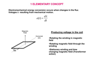
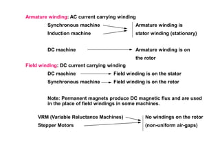
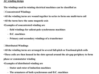
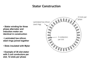
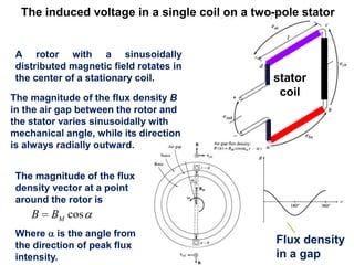
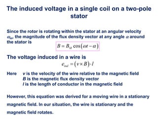
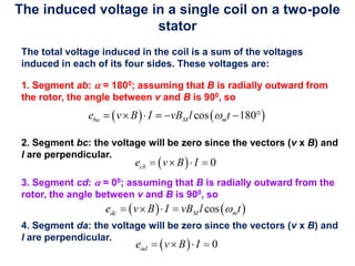
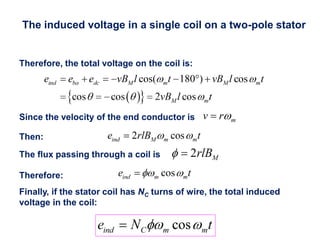
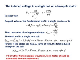
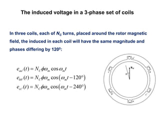
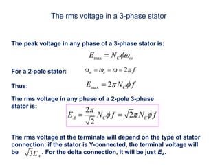
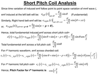
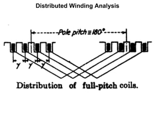
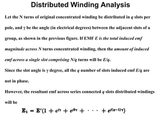
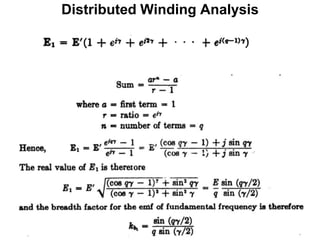
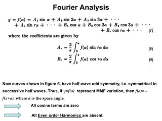
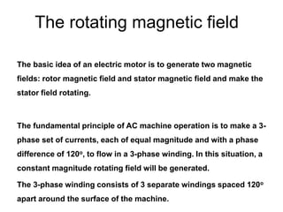
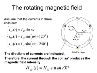
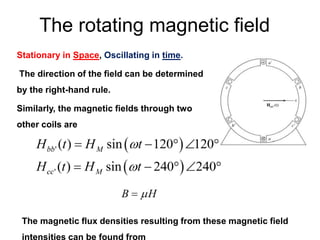
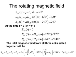
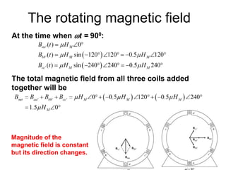
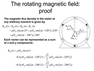
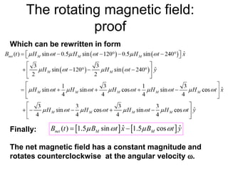
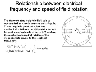
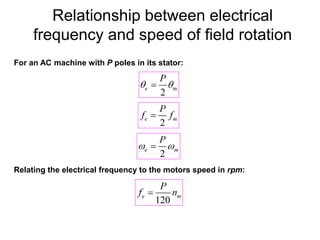
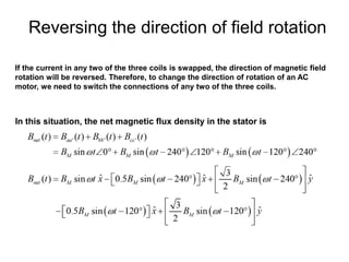
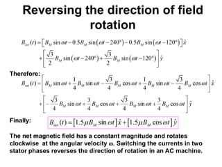
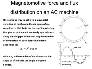
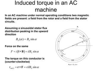
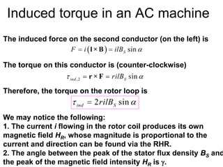
Fundamental
of
rotating machines
By
Dr. S. Rudra
1 ELEMENTARY CONCEPT
Horizontal
axis
Magnetic
Field
e(t)
Electromechanical energy conversion occurs when changes in the flux
linkages λ resulting from mechanical motion.
dt
d
t
e


)
(
•Rotating the winding in magnetic
field
•Rotating magnetic field through the
winding
•Stationary winding and time
changing magnetic field (Transformer
action)
Producing voltage in the coil
Armature winding: AC current carrying winding
Synchronous machine Armature winding is
Induction machine stator winding (stationary)
DC machine Armature winding is on
the rotor
Field winding: DC current carrying winding
DC machine Field winding is on the stator
Synchronous machine Field winding is on the rotor
Note: Permanent magnets produce DC magnetic flux and are used
in the place of field windings in some machines.
VRM (Variable Reluctance Machines) No windings on the rotor
Stepper Motors (non-uniform air-gaps)
AC winding design
The windings used in rotating electrical machines can be classified as
Concentrated Windings
•All the winding turns are wound together in series to form one multi-turn coil
•All the turns have the same magnetic axis
•Examples of concentrated winding are
– field windings for salient-pole synchronous machines
– D.C. machines
– Primary and secondary windings of a transformer
Distributed Windings
•All the winding turns are arranged in several full-pitch or fractional-pitch coils
•These coils are then housed in the slots spread around the air-gap periphery to form
phase or commutator winding
•Examples of distributed winding are
– Stator and rotor of induction machines
– The armatures of both synchronous and D.C. machines
• Stator winding for three
phase alternator and
induction motor are
identical in construction
• Laminated low silicon
steel rings joined together
• Slots insulated with Mylar
• Example of 36 slot stator
with 3 coil conductors per
slot, 12 slots per phase
Stator Construction
Some of the terms common to armature windings are described below:
1.Conductor. A length of wire which takes active part in the
energy- conversion process is a called a conductor.
2.Turn. One turn consists of two conductors.
3.Coil. One coil may consist of any number of turns.
4.Coil –side. One coil with any number of turns has two coil-sides.
Stator Construction
Single layer
Stator
Slots
1 coil arm
per slot
Coil
Stator Construction
Double
layer
Stator
Slots
Coil
2 coil arms
in each slot
EMF of Elementary Alternator
Flux Density across ab plane (1)
Polar Flux and Airgap Flux Density
Preliminary notes
AC machines are AC motors and AC generators.
There are two types of AC machines:
Synchronous machines – the magnetic field current is supplied by
a separate DC power source;
Induction machines – the magnetic field current is supplied by
magnetic induction (transformer action) into their field windings.
The field circuits of most AC machines are located on their rotors.
Every AC (or DC) motor or generator has two parts: rotating part
(rotor) and a stationary part (stator).
The induced voltage in a single coil on a two-pole stator
A rotor with a sinusoidally
distributed magnetic field rotates in
the center of a stationary coil.
The magnitude of the flux density B
in the air gap between the rotor and
the stator varies sinusoidally with
mechanical angle, while its direction
is always radially outward.
Flux density
in a gap
The magnitude of the flux
density vector at a point
around the rotor is
Where  is the angle from
the direction of peak flux
intensity.
stator
coil
The induced voltage in a single coil on a two-pole
stator
Since the rotor is rotating within the stator at an angular velocity
m, the magnitude of the flux density vector at any angle  around
the stator is
The voltage induced in a wire is
Here v is the velocity of the wire relative to the magnetic field
B is the magnetic flux density vector
l is the length of conductor in the magnetic field
However, this equation was derived for a moving wire in a stationary
magnetic field. In our situation, the wire is stationary and the
magnetic field rotates.
The induced voltage in a single coil on a two-pole
stator
The total voltage induced in the coil is a sum of the voltages
induced in each of its four sides. These voltages are:
1. Segment ab:  = 1800; assuming that B is radially outward from
the rotor, the angle between v and B is 900, so
2. Segment bc: the voltage will be zero since the vectors (v x B) and
l are perpendicular.
3. Segment cd:  = 00; assuming that B is radially outward from the
rotor, the angle between v and B is 900, so
4. Segment da: the voltage will be zero since the vectors (v x B) and
l are perpendicular.
The induced voltage in a single coil on a two-pole stator
Therefore, the total voltage on the coil is:
Since the velocity of the end conductor is
Then:
The flux passing through a coil is
Therefore:
Finally, if the stator coil has NC turns of wire, the total induced
voltage in the coil:
The induced voltage in a single coil on a two-pole stator
In other way,
So peak value of the fundamental emf in a single conductor is
Then rms value of a single conductor:
The total emf in a single turn coil:
Finally, if the stator coil has NC turns of wire, the total induced
voltage in the coil:
,
120
m
pn
B lv f where f

  
/* For Other Nonsinusoidal waveform, form factor should be
calculated from the waveform*/
The induced voltage in a 3-phase set of coils
In three coils, each of NC turns, placed around the rotor magnetic
field, the induced in each coil will have the same magnitude and
phases differing by 1200:
The rms voltage in a 3-phase stator
The peak voltage in any phase of a 3-phase stator is:
For a 2-pole stator:
Thus:
The rms voltage in any phase of a 2-pole 3-phase
stator is:
The rms voltage at the terminals will depend on the type of stator
connection: if the stator is Y-connected, the terminal voltage will
be . For the delta connection, it will be just EA.
Induced voltage: Example
Example : The peak flux density of the rotor magnetic field in a
simple 2-pole 3-phase generator is 0.2 T; the mechanical speed of
rotation is 3600 rpm; the stator diameter is 0.5 m; the length of its
coil is 0.3 m and each coil consists of 15 turns of wire. The machine
is Y-connected.
a) What are the 3-phase voltages of the generator as a function of
time?
b) What is the rms phase voltage of the generator?
c) What is the rms terminal voltage of the generator?
The flux in this machine is given by
The rotor speed is
Induced voltage: Example
a) The magnitude of the peak phase voltage is
and the three phase voltages are:
b) The rms voltage of the generator is
c) For a Y-connected generator, its terminal voltage is
• In AC armature windings, the separate coils may be
connected in several different manners, but the two most
common methods are lap and wave
• In polyphase windings it is essential that
 The generated emfs of all the phases are of equal magnitude
 The waveforms of the phase emfs are identical
 The frequency of the phase emfs are equal
 The phase emfs have mutual time-phase displacement of
radians. Here m is the number of phases of the a.c. machine.
2
m

 
Phase Spread
The phase spread of a winding is the
proportion of circumference of the
armature by one phase.
In a 3 φ winding for full pitch coils, each
winding occupies a belt with a breadth
equal to one third of a pole pitch or 60®.
With fractional number of slots per pole,
Nonsinusoidal Distribution of Flux
Density and EMF per Conductor
Point to Remember:
The Time variation of
the emf per conductor
takes the identical form
of space variation of
the flux density
waveform.
Factors Affecting Induced EMF
At any instant, total induced emf across a group of
series connected conductors are nothing but the
algebraic sum of the induced emfs across individual
conductors.
Indeed, it depends on
i) The distribution of the field intensity in the airgap
ii) Placement and interconnection of the conductors
Short Pitch Coil Analysis
Since time variation of induced emf follow point to point space variation of mmf wave (,
emf induced at the left belt will be: (Fundamental)
Similarly, Right hand belt emf will be:
or,
Hence, total fundamental induced emf across short pitch coil=
Total fundamental emf across a full pitch coil:
For rth harmonic waveform, emf across chorded coil:
For rth harmonic full pitch coil=
Hence, Pitch Factor for rth harmonic is
  sin
2
m
left t
E
e t
 



   
sin
2
m
right t x
E
e t x
  
 
 
 
       
 
sin sin sin cos
2
2 2
m m
left right
E E
e t e t e t

    
      
       
   
_ _ sinr sinr sin r cos r
2
2 2
mr mr
r r left r right
E E
e t e t e t

    
 
        
 
       
_ _ sin r
2
mr
r r left r right
E
e t e t e t 
  
Distributed Winding Analysis
Let the N turns of original concentrated winding be distributed in q slots per
pole, and γ be the angle (in electrical degrees) between the adjacent slots of a
group, as shown in the previous figure. If EMF E is the total induced emf
magnitude across N turns concentrated winding, then the amount of induced
emf across a single slot comprising N/q turns will be E/q.
Since the slot angle is γ degree, all the q number of slots induced emf E/q are
not in phase.
However, the resultant emf across series connected q slots distributed windings
will be
Distributed Winding Analysis
Advantages of chorded pitch winding
It saves copper of end connections
Reduction in resistance and inductance of the
winding due to the lesser length of the coil ends
The wave form of the induced emf is improved
The distorting harmonics can be reduced
Due to elimination of high frequency harmonics
eddy current and hysterisis losses are reduced ,
thereby increasing the efficiency
Mechanical strength of coil is increased
Effects of Distribution
In 3 phase winding, coils are placed in
different slots under all pole . This is called
distribution .
Due to this distribution, emf induced in
each slot is not same .
Total voltage induced is the vector sum of
voltages induced in the coil sides .
Advantages of Distributed Winding
Harmonics are reduced
Induced voltage approached sinusoidal wave
form
Armature reaction effect is reduced
Losses are reduced
Efficiency is improved
Provide better cooling
Harmonic Effect
• The flux distribution along the air gaps of
alternators usually is non-sinusoidal so that the
emf in the individual armature conductor likewise
is
• non-sinusoidal
• The sources of harmonics in the output voltage
waveform are the non-sinusoidal waveform of the
field flux.
• Fourier showed that any periodic wave may be
expressed as the sum of a dc component (zero
frequency) and sine (or cosine) waves having
fundamental and multiple or higher frequencies,
the higher frequencies being called harmonics.
Flux Density Variation along Space Angle
Fourier Analysis of Airgap Flux Density
and MMF Distribution
Features of Nonsinusoidal Space Variation of Flux Wave
i) Periodic
ii) Single Valued
iii) Does not include infinite discontinuities
Hence, they can be resolved into a fundamental sine
wave and a series of higher space harmonics.
Fourier Analysis
Now curves shown in figure 6, have half-wave odd symmetry, i.e. symmetrical in
successive half waves. Thus, if y=f(α) represent MMF variation, then f(α)= -
f(π+α), where α is the space angle.
All cosine terms are zero
All Even order Harmonics are absent.
Fourier Analysis
Fourier Analysis
Fourier Analysis
Fourier Analysis
Fourier Analysis
Fourier Analysis
The rotating magnetic field
The basic idea of an electric motor is to generate two magnetic
fields: rotor magnetic field and stator magnetic field and make the
stator field rotating.
The fundamental principle of AC machine operation is to make a 3-
phase set of currents, each of equal magnitude and with a phase
difference of 120o, to flow in a 3-phase winding. In this situation, a
constant magnitude rotating field will be generated.
The 3-phase winding consists of 3 separate windings spaced 120o
apart around the surface of the machine.
The rotating magnetic field
Assume that the currents in three
coils are:
x
x x
. .
.
The directions of currents are indicated.
Therefore, the current through the coil aa’ produces the
magnetic field intensity
Into the page
The rotating magnetic field
Stationary in Space, Oscillating in time.
The direction of the field can be determined
by the right-hand rule.
Similarly, the magnetic fields through two
other coils are
The magnetic flux densities resulting from these magnetic field
intensities can be found from
The rotating magnetic field
At the time t = 0 (t = 0) :
The total magnetic field from all three coils added
together will be
The rotating magnetic field
At the time when t = 900:
The total magnetic field from all three coils added
together will be
Magnitude of the
magnetic field is constant
but its direction changes.
The rotating magnetic field:
proof
x
x x
. .
.
The magnetic flux density in the stator at
any arbitrary moment is given by
Each vector can be represented as a sum
of x and y components:
The rotating magnetic field:
proof
Which can be rewritten in form
Finally:
The net magnetic field has a constant magnitude and
rotates counterclockwise at the angular velocity .
Relationship between electrical
frequency and speed of field rotation
The stator rotating magnetic field can be
represented as a north pole and a south pole.
These magnetic poles complete one
mechanical rotation around the stator surface
for each electrical cycle of current. Therefore,
the mechanical speed of rotation of the
magnetic field equals to the electrical
frequency.
Relationship between electrical
frequency and speed of field rotation
For an AC machine with P poles in its stator:
Relating the electrical frequency to the motors speed in rpm:
Reversing the direction of field rotation
If the current in any two of the three coils is swapped, the direction of magnetic field
rotation will be reversed. Therefore, to change the direction of rotation of an AC
motor, we need to switch the connections of any two of the three coils.
In this situation, the net magnetic flux density in the stator is
Reversing the direction of field
rotation
Therefore:
Finally:
The net magnetic field has a constant magnitude and rotates
clockwise at the angular velocity . Switching the currents in two
stator phases reverses the direction of rotation in an AC machine.
Magnetomotive force and flux
distribution on an AC machine
One obvious way to achieve a sinusoidal
variation of mmf along the air gap surface
would be to distribute the turns of the winding
that produces the mmf in closely spaced slots
along the air gap surface and vary the number
of conductors in each slot sinusoidally,
according to:
where Nc is the number of conductors at the
angle of 00 and  is the angle along the
surface.
Ideal mmf
mmf resulting from
the winding
n0
Induced torque in an AC
machine
In an AC machine under normal operating conditions two magnetic
fields are present: a field from the rotor and a field from the stator
circuits.
Assuming a sinusoidal stator flux
distribution peaking in the upward
direction
Force on the same
The torque on this conductor is
(counter-clockwise)
Induced torque in an AC machine
The torque on this conductor is (counter-clockwise)
The induced force on the second conductor (on the left) is
Therefore, the torque on the rotor loop is
We may notice the following:
1. The current i flowing in the rotor coil produces its own
magnetic field HR, whose magnitude is proportional to the
current and direction can be found via the RHR.
2. The angle between the peak of the stator flux density BS and
the peak of the magnetic field intensity HR is .
Induced torque in an AC machine
Furthermore,
Therefore, the torque on the loop
is
Here K is a constant dependent
on the machine design. Therefore:
Since
Induced torque in an AC machine
As before, k = K/ is a constant dependent on the machine design.
Assuming no saturation, the net magnetic field is a vector sum of
rotor and stator fields:
`Hence,
Since the cross-product of any vector with itself is zero:
Induced torque in an AC
machine
Assuming that the angle between the rotor BR and stator BS
magnetic fields is :
AC Machine Power Flow
and Losses
Sync.
Generator
Induction
Motor

Incomplete PPT on first topic.pptx [Autosaved] [Autosaved].ppt

  • 1.
  • 2.
    1 ELEMENTARY CONCEPT Horizontal axis Magnetic Field e(t) Electromechanicalenergy conversion occurs when changes in the flux linkages λ resulting from mechanical motion. dt d t e   ) ( •Rotating the winding in magnetic field •Rotating magnetic field through the winding •Stationary winding and time changing magnetic field (Transformer action) Producing voltage in the coil
  • 3.
    Armature winding: ACcurrent carrying winding Synchronous machine Armature winding is Induction machine stator winding (stationary) DC machine Armature winding is on the rotor Field winding: DC current carrying winding DC machine Field winding is on the stator Synchronous machine Field winding is on the rotor Note: Permanent magnets produce DC magnetic flux and are used in the place of field windings in some machines. VRM (Variable Reluctance Machines) No windings on the rotor Stepper Motors (non-uniform air-gaps)
  • 4.
    AC winding design Thewindings used in rotating electrical machines can be classified as Concentrated Windings •All the winding turns are wound together in series to form one multi-turn coil •All the turns have the same magnetic axis •Examples of concentrated winding are – field windings for salient-pole synchronous machines – D.C. machines – Primary and secondary windings of a transformer Distributed Windings •All the winding turns are arranged in several full-pitch or fractional-pitch coils •These coils are then housed in the slots spread around the air-gap periphery to form phase or commutator winding •Examples of distributed winding are – Stator and rotor of induction machines – The armatures of both synchronous and D.C. machines
  • 5.
    • Stator windingfor three phase alternator and induction motor are identical in construction • Laminated low silicon steel rings joined together • Slots insulated with Mylar • Example of 36 slot stator with 3 coil conductors per slot, 12 slots per phase Stator Construction
  • 7.
    Some of theterms common to armature windings are described below: 1.Conductor. A length of wire which takes active part in the energy- conversion process is a called a conductor. 2.Turn. One turn consists of two conductors. 3.Coil. One coil may consist of any number of turns. 4.Coil –side. One coil with any number of turns has two coil-sides.
  • 10.
  • 11.
  • 12.
    EMF of ElementaryAlternator Flux Density across ab plane (1)
  • 13.
    Polar Flux andAirgap Flux Density
  • 14.
    Preliminary notes AC machinesare AC motors and AC generators. There are two types of AC machines: Synchronous machines – the magnetic field current is supplied by a separate DC power source; Induction machines – the magnetic field current is supplied by magnetic induction (transformer action) into their field windings. The field circuits of most AC machines are located on their rotors. Every AC (or DC) motor or generator has two parts: rotating part (rotor) and a stationary part (stator).
  • 15.
    The induced voltagein a single coil on a two-pole stator A rotor with a sinusoidally distributed magnetic field rotates in the center of a stationary coil. The magnitude of the flux density B in the air gap between the rotor and the stator varies sinusoidally with mechanical angle, while its direction is always radially outward. Flux density in a gap The magnitude of the flux density vector at a point around the rotor is Where  is the angle from the direction of peak flux intensity. stator coil
  • 16.
    The induced voltagein a single coil on a two-pole stator Since the rotor is rotating within the stator at an angular velocity m, the magnitude of the flux density vector at any angle  around the stator is The voltage induced in a wire is Here v is the velocity of the wire relative to the magnetic field B is the magnetic flux density vector l is the length of conductor in the magnetic field However, this equation was derived for a moving wire in a stationary magnetic field. In our situation, the wire is stationary and the magnetic field rotates.
  • 17.
    The induced voltagein a single coil on a two-pole stator The total voltage induced in the coil is a sum of the voltages induced in each of its four sides. These voltages are: 1. Segment ab:  = 1800; assuming that B is radially outward from the rotor, the angle between v and B is 900, so 2. Segment bc: the voltage will be zero since the vectors (v x B) and l are perpendicular. 3. Segment cd:  = 00; assuming that B is radially outward from the rotor, the angle between v and B is 900, so 4. Segment da: the voltage will be zero since the vectors (v x B) and l are perpendicular.
  • 18.
    The induced voltagein a single coil on a two-pole stator Therefore, the total voltage on the coil is: Since the velocity of the end conductor is Then: The flux passing through a coil is Therefore: Finally, if the stator coil has NC turns of wire, the total induced voltage in the coil:
  • 19.
    The induced voltagein a single coil on a two-pole stator In other way, So peak value of the fundamental emf in a single conductor is Then rms value of a single conductor: The total emf in a single turn coil: Finally, if the stator coil has NC turns of wire, the total induced voltage in the coil: , 120 m pn B lv f where f     /* For Other Nonsinusoidal waveform, form factor should be calculated from the waveform*/
  • 20.
    The induced voltagein a 3-phase set of coils In three coils, each of NC turns, placed around the rotor magnetic field, the induced in each coil will have the same magnitude and phases differing by 1200:
  • 21.
    The rms voltagein a 3-phase stator The peak voltage in any phase of a 3-phase stator is: For a 2-pole stator: Thus: The rms voltage in any phase of a 2-pole 3-phase stator is: The rms voltage at the terminals will depend on the type of stator connection: if the stator is Y-connected, the terminal voltage will be . For the delta connection, it will be just EA.
  • 22.
    Induced voltage: Example Example: The peak flux density of the rotor magnetic field in a simple 2-pole 3-phase generator is 0.2 T; the mechanical speed of rotation is 3600 rpm; the stator diameter is 0.5 m; the length of its coil is 0.3 m and each coil consists of 15 turns of wire. The machine is Y-connected. a) What are the 3-phase voltages of the generator as a function of time? b) What is the rms phase voltage of the generator? c) What is the rms terminal voltage of the generator? The flux in this machine is given by The rotor speed is
  • 23.
    Induced voltage: Example a)The magnitude of the peak phase voltage is and the three phase voltages are: b) The rms voltage of the generator is c) For a Y-connected generator, its terminal voltage is
  • 24.
    • In ACarmature windings, the separate coils may be connected in several different manners, but the two most common methods are lap and wave • In polyphase windings it is essential that  The generated emfs of all the phases are of equal magnitude  The waveforms of the phase emfs are identical  The frequency of the phase emfs are equal  The phase emfs have mutual time-phase displacement of radians. Here m is the number of phases of the a.c. machine. 2 m   
  • 26.
    Phase Spread The phasespread of a winding is the proportion of circumference of the armature by one phase. In a 3 φ winding for full pitch coils, each winding occupies a belt with a breadth equal to one third of a pole pitch or 60®. With fractional number of slots per pole,
  • 27.
    Nonsinusoidal Distribution ofFlux Density and EMF per Conductor Point to Remember: The Time variation of the emf per conductor takes the identical form of space variation of the flux density waveform.
  • 28.
    Factors Affecting InducedEMF At any instant, total induced emf across a group of series connected conductors are nothing but the algebraic sum of the induced emfs across individual conductors. Indeed, it depends on i) The distribution of the field intensity in the airgap ii) Placement and interconnection of the conductors
  • 29.
  • 30.
    Short Pitch CoilAnalysis Since time variation of induced emf follow point to point space variation of mmf wave (, emf induced at the left belt will be: (Fundamental) Similarly, Right hand belt emf will be: or, Hence, total fundamental induced emf across short pitch coil= Total fundamental emf across a full pitch coil: For rth harmonic waveform, emf across chorded coil: For rth harmonic full pitch coil= Hence, Pitch Factor for rth harmonic is   sin 2 m left t E e t          sin 2 m right t x E e t x                    sin sin sin cos 2 2 2 m m left right E E e t e t e t                          _ _ sinr sinr sin r cos r 2 2 2 mr mr r r left r right E E e t e t e t                            _ _ sin r 2 mr r r left r right E e t e t e t    
  • 31.
  • 32.
    Distributed Winding Analysis Letthe N turns of original concentrated winding be distributed in q slots per pole, and γ be the angle (in electrical degrees) between the adjacent slots of a group, as shown in the previous figure. If EMF E is the total induced emf magnitude across N turns concentrated winding, then the amount of induced emf across a single slot comprising N/q turns will be E/q. Since the slot angle is γ degree, all the q number of slots induced emf E/q are not in phase. However, the resultant emf across series connected q slots distributed windings will be
  • 33.
  • 34.
    Advantages of chordedpitch winding It saves copper of end connections Reduction in resistance and inductance of the winding due to the lesser length of the coil ends The wave form of the induced emf is improved The distorting harmonics can be reduced Due to elimination of high frequency harmonics eddy current and hysterisis losses are reduced , thereby increasing the efficiency Mechanical strength of coil is increased
  • 35.
    Effects of Distribution In3 phase winding, coils are placed in different slots under all pole . This is called distribution . Due to this distribution, emf induced in each slot is not same . Total voltage induced is the vector sum of voltages induced in the coil sides .
  • 36.
    Advantages of DistributedWinding Harmonics are reduced Induced voltage approached sinusoidal wave form Armature reaction effect is reduced Losses are reduced Efficiency is improved Provide better cooling
  • 37.
    Harmonic Effect • Theflux distribution along the air gaps of alternators usually is non-sinusoidal so that the emf in the individual armature conductor likewise is • non-sinusoidal • The sources of harmonics in the output voltage waveform are the non-sinusoidal waveform of the field flux. • Fourier showed that any periodic wave may be expressed as the sum of a dc component (zero frequency) and sine (or cosine) waves having fundamental and multiple or higher frequencies, the higher frequencies being called harmonics.
  • 39.
    Flux Density Variationalong Space Angle
  • 41.
    Fourier Analysis ofAirgap Flux Density and MMF Distribution Features of Nonsinusoidal Space Variation of Flux Wave i) Periodic ii) Single Valued iii) Does not include infinite discontinuities Hence, they can be resolved into a fundamental sine wave and a series of higher space harmonics.
  • 42.
    Fourier Analysis Now curvesshown in figure 6, have half-wave odd symmetry, i.e. symmetrical in successive half waves. Thus, if y=f(α) represent MMF variation, then f(α)= - f(π+α), where α is the space angle. All cosine terms are zero All Even order Harmonics are absent.
  • 43.
  • 44.
  • 45.
  • 46.
  • 47.
  • 48.
  • 53.
    The rotating magneticfield The basic idea of an electric motor is to generate two magnetic fields: rotor magnetic field and stator magnetic field and make the stator field rotating. The fundamental principle of AC machine operation is to make a 3- phase set of currents, each of equal magnitude and with a phase difference of 120o, to flow in a 3-phase winding. In this situation, a constant magnitude rotating field will be generated. The 3-phase winding consists of 3 separate windings spaced 120o apart around the surface of the machine.
  • 54.
    The rotating magneticfield Assume that the currents in three coils are: x x x . . . The directions of currents are indicated. Therefore, the current through the coil aa’ produces the magnetic field intensity Into the page
  • 55.
    The rotating magneticfield Stationary in Space, Oscillating in time. The direction of the field can be determined by the right-hand rule. Similarly, the magnetic fields through two other coils are The magnetic flux densities resulting from these magnetic field intensities can be found from
  • 56.
    The rotating magneticfield At the time t = 0 (t = 0) : The total magnetic field from all three coils added together will be
  • 57.
    The rotating magneticfield At the time when t = 900: The total magnetic field from all three coils added together will be Magnitude of the magnetic field is constant but its direction changes.
  • 58.
    The rotating magneticfield: proof x x x . . . The magnetic flux density in the stator at any arbitrary moment is given by Each vector can be represented as a sum of x and y components:
  • 59.
    The rotating magneticfield: proof Which can be rewritten in form Finally: The net magnetic field has a constant magnitude and rotates counterclockwise at the angular velocity .
  • 60.
    Relationship between electrical frequencyand speed of field rotation The stator rotating magnetic field can be represented as a north pole and a south pole. These magnetic poles complete one mechanical rotation around the stator surface for each electrical cycle of current. Therefore, the mechanical speed of rotation of the magnetic field equals to the electrical frequency.
  • 61.
    Relationship between electrical frequencyand speed of field rotation For an AC machine with P poles in its stator: Relating the electrical frequency to the motors speed in rpm:
  • 62.
    Reversing the directionof field rotation If the current in any two of the three coils is swapped, the direction of magnetic field rotation will be reversed. Therefore, to change the direction of rotation of an AC motor, we need to switch the connections of any two of the three coils. In this situation, the net magnetic flux density in the stator is
  • 63.
    Reversing the directionof field rotation Therefore: Finally: The net magnetic field has a constant magnitude and rotates clockwise at the angular velocity . Switching the currents in two stator phases reverses the direction of rotation in an AC machine.
  • 64.
    Magnetomotive force andflux distribution on an AC machine One obvious way to achieve a sinusoidal variation of mmf along the air gap surface would be to distribute the turns of the winding that produces the mmf in closely spaced slots along the air gap surface and vary the number of conductors in each slot sinusoidally, according to: where Nc is the number of conductors at the angle of 00 and  is the angle along the surface. Ideal mmf mmf resulting from the winding n0
  • 65.
    Induced torque inan AC machine In an AC machine under normal operating conditions two magnetic fields are present: a field from the rotor and a field from the stator circuits. Assuming a sinusoidal stator flux distribution peaking in the upward direction Force on the same The torque on this conductor is (counter-clockwise)
  • 66.
    Induced torque inan AC machine The torque on this conductor is (counter-clockwise) The induced force on the second conductor (on the left) is Therefore, the torque on the rotor loop is We may notice the following: 1. The current i flowing in the rotor coil produces its own magnetic field HR, whose magnitude is proportional to the current and direction can be found via the RHR. 2. The angle between the peak of the stator flux density BS and the peak of the magnetic field intensity HR is .
  • 67.
    Induced torque inan AC machine Furthermore, Therefore, the torque on the loop is Here K is a constant dependent on the machine design. Therefore: Since
  • 68.
    Induced torque inan AC machine As before, k = K/ is a constant dependent on the machine design. Assuming no saturation, the net magnetic field is a vector sum of rotor and stator fields: `Hence, Since the cross-product of any vector with itself is zero:
  • 69.
    Induced torque inan AC machine Assuming that the angle between the rotor BR and stator BS magnetic fields is :
  • 70.
    AC Machine PowerFlow and Losses Sync. Generator Induction Motor